

Page 1
0035
Construction
The safety valve comprises:
•Housing
• Spring bonnet
• Venting bonnet
• Rubber bellows
• Adjustment spring
Materials
• Brass housing
• Spring bonnet of cast iron, powder coated
• Venting bonnet of polyamid
• Bellows of silicon caoutchouc
• Spring steel adjustment spring
• Disc seal of Viton
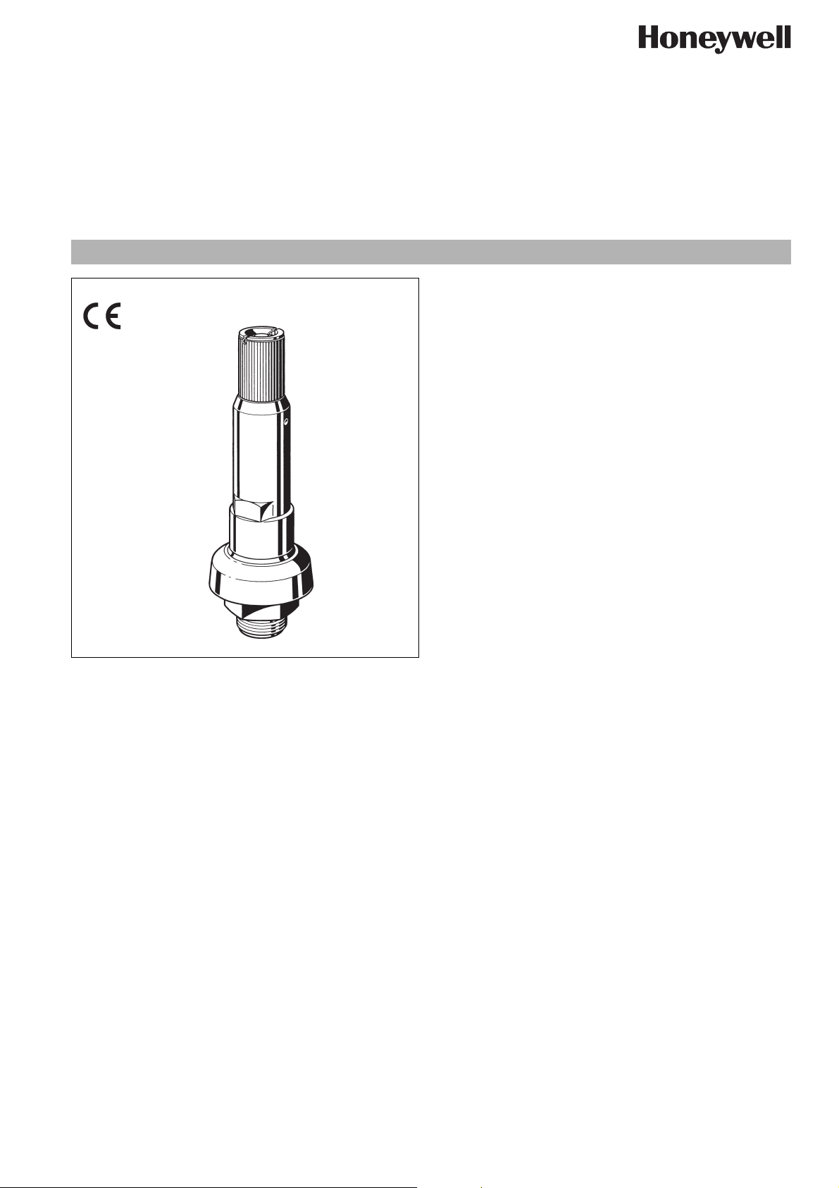
S245S
Safety Valve
High performance valve for compressed air
Product specification sheet
Application
Safety valves of this type are direct loaded high performance
safety valves with lifting device. The venting bonnet discharges
the medium downwards.
Safety valves of this type protect fixed vessels containing granular
or powdered materials or silo tank vehicles containing fluids,
granular or powdered materials which are unloaded using
compressed air.
Special Features
• Sturdy metal construction
• Shakeproof lifting mechanism admitting no additional load
• Rubber bellows for protection of moving parts
• Venting bonnet for downwards discharge of fluid
• Approved to AD information sheet A 2 and to VdTÜV information sheet safety valve 100 for set relief pressure between 0.9
and 4.3 bar
• Set pressure adjustment at factory
• Set pressure settings possible between 0.5 and 30 bar in
steps of 0.1 bar
• Certified to Pressure Equipment Directive 97/23/EC, Reference No. CE 0035
Range of Application
Compressed air for discharge of granular or powdered materials
from fixed vessels and for liquid, granular or powdered materials
from silo tank vehicles.
Technical Data
Operating temperature max. 180 °C
Pressure setting between 0.9 and 4.3 bar
in steps of 0.1 bar
Approval No. TÜV · SV · ..* · 930 · 28 · F/K/S · w · p
P = set pressure
Discharge rate αw = 0.52 (0.9 -1.3 bar)
αw = 0.59 (1.4 - 2.0 bar)
αw = 0.63 (2.1 - 4.3 bar)
Connection size G 1
..* valid Approval No.
1
/4" and G 11/2"
EN0H-1310GE23 R0807 • Subject to change
www.honeywell.com 39
Page 2
S245S Safety Valve
Method of Operation
Safety valves are direct-acting. The disc seal is pushed up by the
pressure from the system against a spring which is holding the
valve closed. If the opening force exceeds the force exerted by
the spring, the valve disc is lifted off the valve seat and the valve
discharges the medium. In accordance with the requirements of
the standard, the full discharge capacity of the valve will be
achieved when the system pressure climbs to no more than 10%
above the set pressure of the valve. Full shutoff must be achieved
if the system pressure falls to below 90% of the nominal set pressure value.
The bellows protect the gliding parts inside the safety valve
against impurities.
Options
S245S- ... Z...= Special setting
Connection size
Set pressure
Ordering Example
S245B-11/4Z2.0 = Safety valve, size 1
1
/4", set pressure
2.0 bar
Connection size G 11/4"1
1
/2"
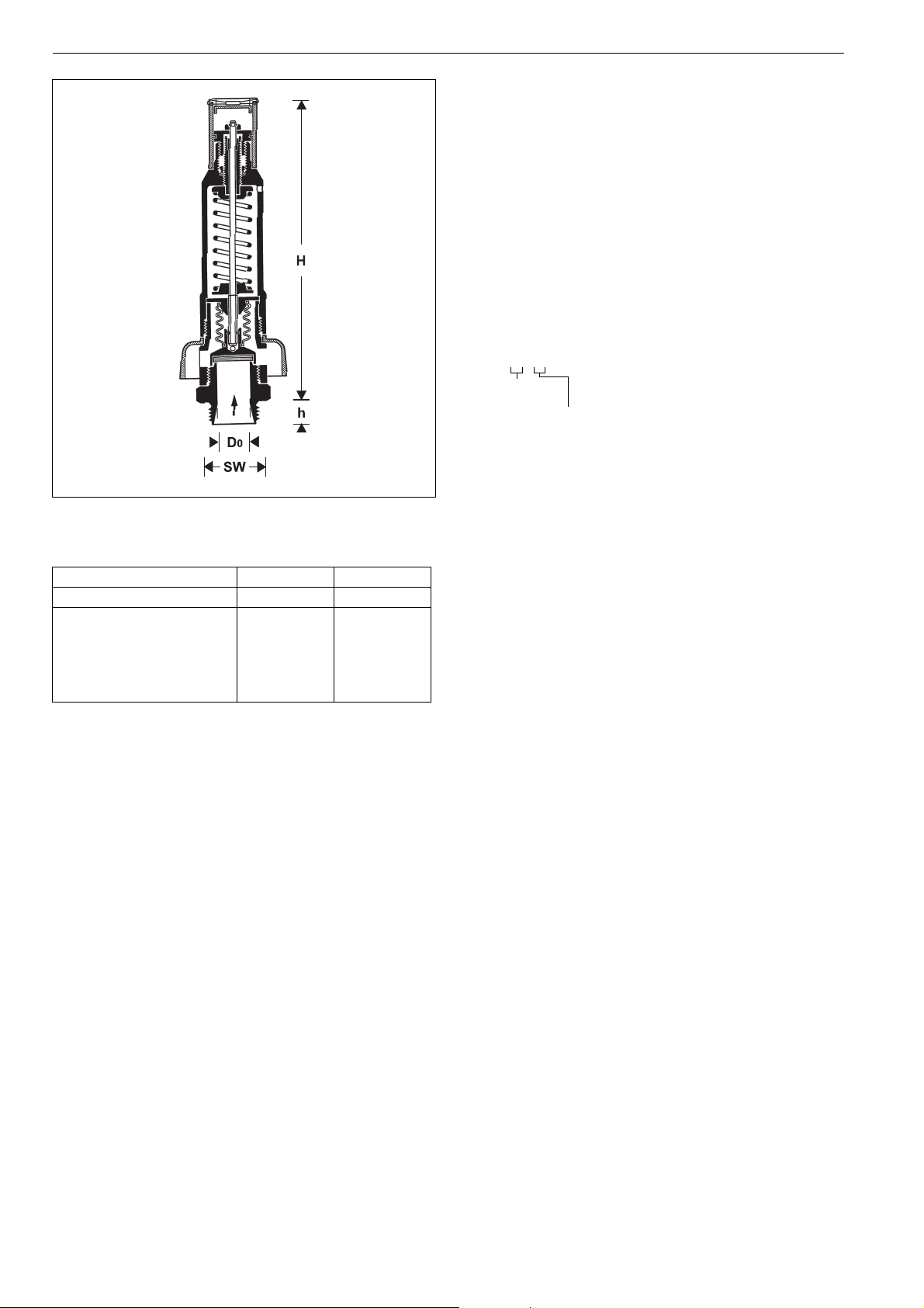
Weight kg 2.0 2.0
Dimensions mm
D
SW
0
h
H
28
18
258
55
28
20
258
55
40 www.honeywell.com
EN0H-1310GE23 R0807 • Subject to change
Page 3
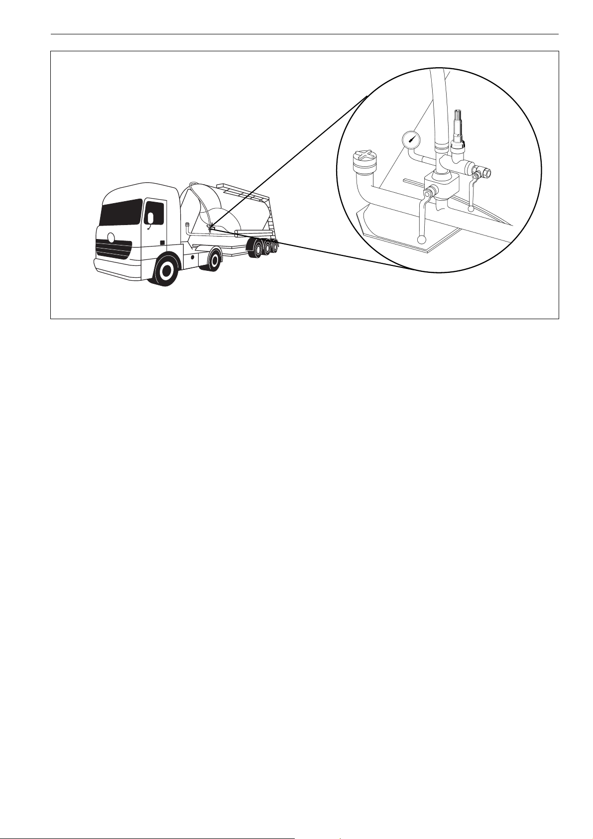
Installation Example
S245S Safety Valve
Installation Guidelines
• Install the valve vertically upwards in pipework or on a pressure vessel
o Never install in a horizontal position or vertically downwards
• Install the safety valve in such a way that during venting no
harm can occur to persons or objects adjacent to the unit
o Under some circumstances it is possible that high volumes
can discharge downwards
• Minimum clearances must be adhered to (see installation
instruction)
• No strainer or shut-off valves may be installed in the pipe
leading to the valve
• There must not be any shut-off devices in the feeding pipe.
The cross section of the feeding pipe may not be smaller than
the entrance cross section of the safety valve. The pressure
drop in the feeding pipe must not exceed 3 % of the pressure
difference between opening overpressure and superimposed
back pressure during the greatest mass flow which is to be
carried off
Typical Applications
Safety valves of this type are fitted where there is a risk of excess
pressures which may injure people or damage equipment.
The following are some typical applications:
• Silo tank vehicles
• Fixed vessels
EN0H-1310GE23 R0807 • Subject to change
www.honeywell.com 41
Page 4
S245S Safety Valve
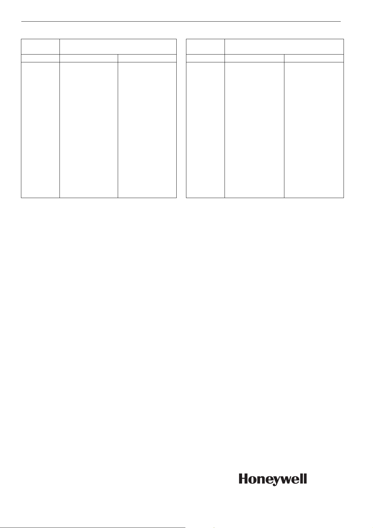
Discharged capacity for compressed air
Opening pressure
bar 1 1/4"1
0.9
1.0
1.1
1.2
1.3
1.4
1.5
1.6
1.7
1.8
1.9
2.0
2.1
2.2
2.3
2.4
2.5
2.6
Amount of air in Nm3/h (0 °C, 1.013 bar)
1
/2"
438
462
486
510
606
462
660
688
715
742
770
797
880
909
938
967
997
1026
438
462
486
510
606
462
660
688
715
742
770
797
880
909
938
967
997
1026
Opening pres-
Amount of air in Nm3/h (0 °C, 1.013 bar)
sure
bar 1 1/4"1
2.7
2.8
2.9
3.0
3.1
3.2
3.3
3.4
3.5
3.6
3.7
3.8
3.9
4.0
4.1
4.2
4.3
The full discharge capacity is achieved at 10 % increase of system pressure above
set pressure.
1055
1084
1113
1142
1171
1200
1230
1259
1288
1317
1346
1375
1404
1433
1463
1492
1521
1
/2"
1055
1084
1113
1142
1171
1200
1230
1259
1288
1317
1346
1375
1404
1433
1463
1492
1521
Automation and Control Solutions
Honeywell GmbH
Hardhofweg
D-74821 Mosbach
Phone: (49) 6261 810
Fax: (49) 6261 81309
http://europe.hbc.honeywell.com
www.honeywell.com
Manufactured for and on behalf of the
Environmental and Combustion Controls Division
of Honeywell Technologies Sàrl, Ecublens, Route
du Bois 37, Switzerland by its Authorised Representative Honeywell GmbH
EN0H-1310GE23 R0807
Subject to change without notice
© 2007 Honeywell GmbH
 Loading...