

Page 1
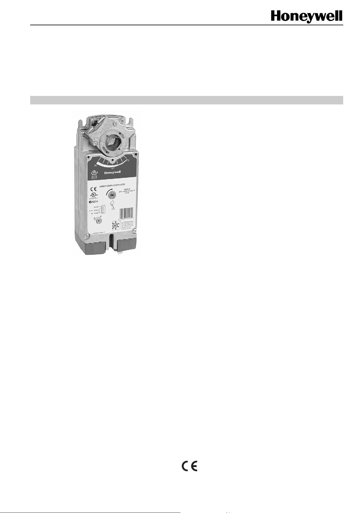
S10010 / S20010
SPRING RETURN DIRECT-COUPLED DAMPER ACTUATORS
10/20 Nm (88/177 lb-in) FOR MODULATING AND FLOATING CONTROL
PRODUCT DATA
SPECIFICATIONS
Supply voltage
S10010 / S20010 24 Vac ±20% / 24 Vdc,
50/60 Hz
Nominal voltage
S10010 / S20010 24 Vac / 24 Vdc, 50/60 Hz
All values stated hereinafter apply to operation under
nominal voltage conditions.
Power consumption Holding Driving
S10010 5 VA / 5 W 14 VA
S20010 5 VA / 5 W 16 VA
Ambient limits
Ambient operating limits -40...+60 °C
Ambient storage limits -40...+70 °C
Relative humidity 5...95%, non-condensing
Safety
Protection standard IP54
Protection class II as per EN 60730-1
Overvoltage category III
Lifetime
GENERAL
These direct-coupled damper actuators provide modulating /
floating control for:
• air dampers,
• VAV units,
• air handlers,
• ventilation flaps,
• louvers, and
• reliable control for air damper applications with up to
2
1.5 m
/ 16 sq.ft (10 Nm / 88 lb-in) or 4.6 m2 / 50 sq.ft.
(20 Nm / 177 lb-in) (seal-less dampers; air frictiondependent).
FEATURES
• Self-centering shaft adapter
• Removable access cover
• Mechanical end limits (non-adjustable)
• Rotation direction selectable by choice of mounting
orientation
• Mountable in any orientation (IP54 only when
mounted on a horizontal shaft with access cover
below the shaft)
• Mechanical position indicator
Full strokes 60000
Repositions 1.5 million
Full stroke spring return 60000
Mounting
Round damper shaft 10...27 mm
Square damper shaft 13...19 mm
Shaft length 25 mm
End switch (when included)
Rating 5 A (resistive) / 3 A (induct.)
Triggering points 7° / 85°
Torque rating
S10010 10 Nm (88 lb-in)
S20010 20 Nm (177 lb-in)
Runtime 90 sec (50 Hz)
Spring return timing 20 sec (50 Hz)
Rotation stroke 95° ± 3°
Dimensions see Fig. 8 on page 6
Weight 3.2 kg
Noise rating
Driving 40 dB(A)
Holding 20 dB(A) (no audible noise)
Spring return 50 dB(A)
® U.S. Registered Trademark EN0B-0463GE51 R0505
Copyright © 2005 Honeywell Inc. • All rights reserved
Page 2
SmartAct S10010, S20010
MODELS
order number supply voltage end switches power consumption torque
S10010 -S10010-SW2 2
S20010 -S20010-SW2
24 Vac / 24 Vdc
2
Product Identification System
N = non-spring return
S = spring return
10 = 10 Nm (88 lb-in)
20 = 20 Nm (177 lb-in)
010 = modulating + floating
24 = 24 V
230 = 230 V
14 VA (driving) / 5 VA (holding) 10 Nm (88 lb-in)
16 VA (driving) / 5 VA (holding) 20 Nm (177 lb-in)
SmartAct
Fig. 1. Product Identification System
S
2
0
OPERATION / FUNCTIONS
Contents of Package
1 Self-centering shaft adapter
2 Retainer clip
3 Rotational angle scales (0...90° / 90...0°)
4 Mechanical end limits (non-adjustable)
5 Hex wrench for manual adjustment
6 Rotation direction switch
7 Access cover
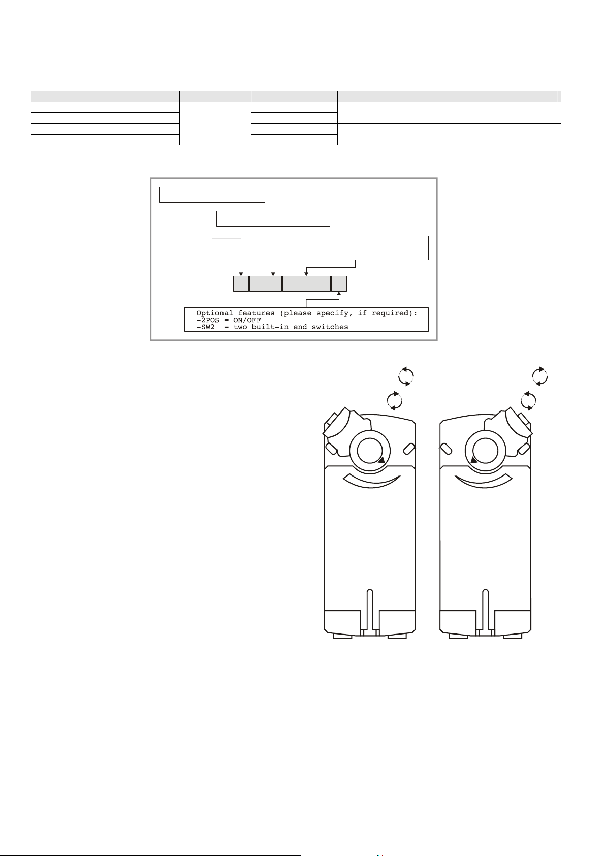
Rotary Movement
The actuators are designed to open a damper by driving the
damper shaft in either a clockwise or counterclockwise
direction.
NOTE: Actuators are shipped in the fully-closed (spring
return) position.
Position Indication
An arrow molded into the hub points to tick marks on the label
to indicate the hub rotary position.
320
X
CCW to close
(failsafe position)
CW to open
90° 0°
45°
CW to close
(failsafe position)
CCW to open
90°0°
45°
EN0B-0463GE51 R0505 2
Fig. 2. Mounting orientation
Page 3

SmartAct S10010, S20010
Manual Adjustment
IMPORTANT
To prevent equipment damage, before manual
adjustment, you must remove power.
The actuator can be operated with no power present. Use this
feature during installation or to move and lock the damper or
valve shaft position when there is no power.
Operating the Manual Positioning
To operate the manual positioning with no power, proceed as
follows:
1. If the power is ON, turn it OFF.
2. Insert the supplied hex wrench (key) as shown in Fig. 3.
3. Rotate the key in the direction indicated on the cover.
4. Once the desired position has been reached, hold the key
to prevent the spring return from moving the actuator.
5. With the key held in place, use a screwdriver to turn the
gear train lock pin in the indicated direction until the detent
is reached.
NOTE: At the detent, the pin resists further rotation.
6. Remove the key without rotating it further.
Releasing the Manual Positioning
To release the manual positioning with no power present,
proceed as follows:
1. Insert the supplied key.
2. Turn the key ¼ of a turn in the direction indicated on the
cover.
3. Remove the key without engaging the gear train lock pin.
4. The spring will return the actuator to the failsafe position.
NOTE: Once power is restored, the actuator will return to
normal automated control.
95°
1
3
Internal End Switches
NOTE: Only those actuators for which "-SW2" has been
specified when ordering (e.g.: "S10010-SW2")
feature internal end switches.
The internal end switches are set to switch from "common" to
"normally open" at angles of 7° (±3°) and 85° (±3°),
respectively, from the totally counterclockwise position.
actuator scale: clockwise
10° 15° 92.5°0° 90°-2.5° 83°80°75°
7°
CCW internal
auxiliary switch
end switch scale
10° 15°0° 90°83°80°75°
7°
actuator scale: counterclockwise
83° 80° 75° -2.5°90° 0°92.5° 7°10°15°
Fig. 4. Internal end switch triggering points
CW internal
auxiliary switch
Mechanical Stroke Limit Reduction
For applications requiring a span of less than 95°, a simple
adjustment can be made. When the rotational mounting of the
shaft coupling is changed, the actuator drives less than the
full 95° stroke.
The stroke is adjustable in 5° increments. Once adjusted, the
actuator drives until the shaft coupling reaches the
mechanical stop (part of the housing). The stop causes the
motor to discontinue driving, and the shaft coupling drives no
farther. When the actuator returns, it stops at the fail-safe
position.
To set the fail-safe position, proceed as follows:
1. Remove the retainer clip from the shaft coupling and set it
aside for later use.
2. Remove the shaft coupling from the actuator.
3. Rotate the coupling to the desired fail-safe position,
aligning it based on the stroke labeling. See Fig. 5.
EXAMPLE: Setting the shaft coupling to an approx. fail-safe
position of 35° (as indicated on the housing)
limits the stroke to 60° (see Fig. 5).
4. Install the shaft coupling at this position.
5. Replace the retainer clip on the shaft coupling using the
groove of the coupling.
6. If necessary, replace the holder and position indicator on
the shaft coupling.
2
Fig. 3. Manual positioning
3 EN0B-0463GE51 R0505
Page 4

SmartAct S10010, S20010
90°
45° 45°
DRIVE
SPRING RETURN
90° STROKE
0°
Fig. 5. Stroke reduction
90°
0°
D
R
I
V
E
S
P
R
I
N
G
R
E
T
U
R
N
6
0
°
S
T
R
O
K
E
INSTALLATION
These actuators are designed for single-point mounting.
IMPORTANT
To prevent equipment damage, before manual
operation, you must remove power.
Mounting Instructions
All information and steps are included in the Installation
Instructions supplied with the actuator.
Mounting Position
The actuators can be mounted in any position (IP54 only
when mounted on a horizontal shaft with access cover below
the shaft). Choose a mounting position permitting easy
access to the actuator's cables and controls. When stationing
outdoors, equip with suitable cover to protect against UV and
rain.
Mounting Bracket and Screws
If the actuator is to be mounted directly on a damper shaft,
use the mounting bracket included in the delivery package.
Self-Centering Shaft Adapter
The self-centering shaft adapter can be used for shafts
having various diameters and shapes (round: 10...27 mm;
square: 13...19 mm).
In the case of short shafts, the shaft adapter may be reversed
and mounted on the duct side.
Stroke
The stroke amounts to 95° (±3°) and is mechanically limited
by end limits (non-adjustable).
Wiring
Connecting to the Power Supply
In order to comply with protection class II, the power source of
24 V actuators must be reliably separated from the network
power supply circuits as per DIN VDE 0106, part 101.
Access Cover
To facilitate wiring the actuator to the controller, the access
cover can be detached from the actuator.
IMPORTANT
Remove power before detaching the access cover.
Once the access cover has been removed, please take
care to avoid damaging any of the parts now
accessible.
1234
S1 S2 S3 S4 S5 S6 1234
5
5
Fig. 6. Access cover (S10010-SW2)
EN0B-0463GE51 R0505 4
Fig. 7. S10010-SW2 with access cover removed
Page 5

Wiring Diagrams
S10010 / S20010
SmartAct S10010, S20010
TERMINAL STRIP 1
24 Vac~
CW
CCW
0...10 Vdc
!
1
2
3
4
5
Connect via safety isolating transf ormer!
FLOATING CONTROL
Function Switch
Position*
2-10 VDC Modulating
10-2 VDC Modulating
0-10 VDC Modulating
10-0 VDC Modulating
Floating, Forward
Floating, Reverse
*Shown in factory setting
24 Vac~
0(2)...10 Vdc
10...0(2) Vdc
0(2)...10 Vdc
10...0(2) Vdc
Y
U
Connect via safety isolating transformer!
!
MODULATING CONTROL
Function Switch
1
2
3
4
*Shown in factory setting
5
Position*
S10010-SW2 / S20010-SW2
TERMINAL STRIP 1
24 Vac~
CW
CCW
0...10 Vdc
!
1
2
3
4
5
Connect via safety isolating transformer!
FLOATING CONTROL
Function Switch
Position*
2-10 VDC Modulating
10-2 VDC Modulating
0-10 VDC Modulating
10-0 VDC Modulating
Floating, Forward
Floating, Reverse
*Shown in factory setting
24 Vac~
0(2)...10 Vdc
10...0(2) Vdc
0(2)...10 Vdc
10...0(2) Vdc
Y
U
Connect via safety isolating transformer!
!
MODULATING CONTROL
Function Switch
1
2
3
4
*Shown in factory setting
5
Position*
NOTE: Internal end switches S1 and S4 must be connected to the same power source.
2-10 VDC Modulating
10-2 VDC Modulating
0-10 VDC Modulating
10-0 VDC Modulating
Floating, Forward
Floating, Reverse
2-10 VDC Modulating
10-2 VDC Modulating
0-10 VDC Modulating
10-0 VDC Modulating
Floating, Forward
Floating, Reverse
S1 black
S2 black
S3 black
S4 gray
S5 gray
S6 gray
END SWITCHES
S1
S2
S3
S4
S5
S6
5 EN0B-0463GE51 R0505
Page 6

SmartAct S10010, S20010
DIMENSIONS
100
50 50
40
156
76 (min. from shaft end)
64 (min.)
247
6
76 (min.)
Fig. 8. Dimensions (in mm)
Automation and Control Solutions
Honeywell GmbH
Böblinger Straße 17
D-71101 Schönaich
Phone: (49) 7031 63701
Fax: (49) 7031 637493
http://europe.hbc.honeywell.com
Subject to change without notice. Printed in Germany Manufacturing location certified to
EN0B-0463GE51 R0505
75
 Loading...