

Page 1
32-00157-03
RM7890A,B/EC7890A,B
7800 SERIES Relay Modules
INSTALLATION INSTRUCTIONS
APPLICATION
The Honeywell RM7890A,B,C/EC7890A,B Relay Modules
are microprocessor based integrated burner controls for
on/off automatically fired gas, oil, or combination fuel
single burner applications. The RM/EC7890 Relay Module
is intended to replace the RA890F,G, H Protectorelay®
Primary Control. The RM/EC7890 System consists of a
relay module, subbase, and amplifier. Options include: 2line VFD (see document 65-0090) or 4-line LCD (see
document 32-00110) Keyboard Display Module, and
remote display mounting.
Functions the RM/EC7890 provides include automatic
burner on/off sequencing, flame supervision, system
status indication, system or self-diagnostics and
troubleshooting.
This document provides installation and static checkout
instructions. Other applicable publications are:
Publication
No. Product
32-00110 S7800A2142 4-line LCD Keyboard Display
Module Product Data
32-0167 Q7800A/B Wiring Subbase Product Data
32-0166 204729A/C KDM NEMA4 Covers for 4-line
LCD KDM
65-0090 S7800A 2-line Keyboard Display Module
Product Data.
65-0091 S7810A Data ControlBus Module™ Product
Data.
65-0095 S7820 Remote Reset Module Product Data.
65-0097 221729C Dust Cover Packing Instructions.
65-0109 Flame Amplifiers for the 7800 SERIES
Product Data.
65-0131 221818A,C Extension Cable Assembly
Product Data.
65-0229 7800 SERIES Relay Modules Checkout and
Troubleshooting.
65-0249 S7810M ModBus Module.
This document covers the following 7800 Series Relay
Modules:
1000-Series 2000-Series
• RM7890A1015 • RM7890B2014
• RM7890A1031 • RM7890A2015
• RM7890A1064 • RM7890B2030
• RM7890B1014 • RM7890A2031
• RM7890B1030 • RM7890B2055
• RM7890B1055 • RM7890A2064
• EC7890B1028
SPECIFICATIONS
Electrical Ratings (See Table 3):
Voltage and Frequency:
RM7890: 120 Vac (+10/-15%), 50/60 Hz (±10%).
EC7890: 220-240 Vac (+10%/-15%), 50/60 Hz (±10%).
Power Dissipation: 10W maximum.
Maximum Total Connected Load: 2000 VA.
Fusing Total Connected Load: 15A maximum, type SC
or equivalent, fast blow.
Environmental Ratings:
Ambient Temperature:
Operating: -40°F to +140°F (-40°C to +60°C).
Storage: -40°F to +150°F (-40°C to +66°C).
Humidity: 85% relative humidity continuous, noncon-
densing.
Vibration: 0.5G environment.
SIL 3 Capable
SIL 3 Capable in a properly designed Safety Instrumented
System. See form number 65-0312 for Certificate
Agreement.
SIL
3
Capable
EC7890B1028, RM7890A1064,
RM7890B1055, RM7890A2064,
or RM7890B2055 only.
Page 2

RM7890A,B/EC7890A,B 7800 SERIES RELAY MODULES
WARNING
WARNING
Approvals:
RM7890A,B:
Underwriters Laboratories Inc. Listed: File No. MP268.
ANSI/UL 60730-2-5 / CSA C22.2 No. 60730-2-5 Automatic Electrical Controls for Household and
Similar
Use, Part 2-5: Particular Requirements for Automatic
Electrical Burner Control Systems
Factory Mutual Approved: Report No. 1V9A0.AF.
CE approved - only RM7890A1064, RM7890B1055,
RM7890A2064, RM7890B2055
EAC: TC N RU д-US.Aи3O.B.04013
Federal Communications Commission: Part 15, Class B,
Emissions.
EC7890:
CE approved
EAC: TC N RU д-US.Aи3O.B.04013
Federal Communications Commission: Part 15,
Class B, Emissions.
CE approvals cover:
Gas Appliances Regulation: 2016/426/EU GAR
Low Voltage Directive: 2014/35/EU LVD.
EMC Directive: 2014/30/EU EMC (Immunity Emission
conformity can only be verified in combination with
the appliance).
KIWA: certificate # 18GR0996/00, PIN 0063CT1466
Applicable Standards:
EN 298:2012 Automatic burner controls
EN 60335-2-102 Household and similar electrical
appliances
EN 746-2 Industrial thermoprocessing - fuel handling
systems
NOTE:
RM7890A1064, RM7890B1055, RM7890A2064
and RM7890B2055
are rated cULus and CE.
INSTALLATION
Fire or Explosion Hazard.
Can cause property damage, serious injury, or
death.
To prevent possible hazardous burner operation,
verify safety requirements each time a control is
installed on a burner.
Electrical Shock Hazard.
Can cause personal injury, death or equipment
damage.
Disconnect the power supply before beginning
installation.
When Installing this Product...
1. Read these instructions carefully. Failure to follow
them could damage the product or cause a
hazardous condition.
2. Check the ratings given in the instructions and
marked on the product to make sure the product is
suitable for the application.
3. Installer must be a trained, experienced, flame
safeguard service technician.
4. After installation is complete, check out the product
operation as provided in these instructions.
IMPORTANT
1.
Wiring connections for the relay modules are unique;
refer to Fig. 2 or the appropriate Specifications for individual subbase wiring.
2. Wiring must comply with all applicable codes,
ordinances and regulations.
3. Wiring must comply with NEC Class 1 (Line Voltage)
wiring.
4. Loads connected to the RM/EC7890 must not exceed
those listed on the RM/EC7890 label or the Specifications; see Tables 3, 4, and 5.
5. Limits and interlocks must be rated to simultaneously
carry and break current to the ignition transformer,
pilot valve, and main fuel valve(s).
6. All external timers must be listed or componentrecognized by authorities who have proper jurisdiction.
7. For on-off gas-fired systems, some authorities who
have jurisdiction prohibit the wiring of any limit or
operating contacts in series between the flame
safeguard control and the main fuel valve(s).
8. Two flame detectors can be connected in parallel with
the following exceptions:
•C7927 Ultraviolet Detector
•C7915 Infrared Detector
9. This equipment generates, uses and can radiate radio
frequency energy and, if not installed and used in
accordance with the instructions, can cause
interference with radio communications. It has been
tested and found to comply with the limits for a Class B
computing device of Part 15 of FCC rules which are
designed to provide reasonable protection against
such interference when operated in a commercial
environment. Operation of this equipment in a
residential area can cause interference, in which case,
the users, at their own expense, may be required to take
whatever measures are required to correct this
interference.
10.This digital apparatus does not exceed the Class B limits for radio noise for digital apparatus set out in the
Radio Interference Regulations of the Canadian
Department of Communications.
Location
Humidity
Install the relay module where the relative humidity never
reaches the saturation point. The relay module is designed
to operate in a maximum 85% relative humidity
continuous, noncondensing, moisture environment.
Condensing moisture can cause a safety shutdown.
Vibration
Do not install the relay module where it can be subjected
to vibration in excess of 0.5G continuous maximum
vibration.
Weather
The relay module is not designed to be weather tight.
When installed outdoors, protect the relay module in an
approved weather-tight enclosure.
32-00157-03 2
Page 3

RM7890A,B/EC7890A,B 7800 SERIES RELAY MODULES
WARNING
Mounting Wiring Subbase
1. Mount the subbase in any position except horizon-
tally with the bifurcated contacts pointing down. The
standard vertical position is recommended. Any
other position decreases the maximum ambient
temperature rating.
2. Select a location on a wall, burner or electrical panel.
The Q7800 can be mounted directly in the control
cabinet. Be sure to allow adequate clearance for servicing, installation, access or removal of the relay
module, Expanded Annunciator, Keyboard Display
Module, flame amplifier, flame amplifier signal voltage probes, Run/Test Switch, electrical signal voltage probes and electrical field connections.
3. For surface mounting, use the back of the subbase
as a template to mark the four screw locations. Drill
the pilot holes.
4. Securely mount the subbase using four no. 6 screws.
Wiring Subbase
NOTE: There are several different subbase models that
can be purchased. It is important to note which
subbase is compatible with the relay module
when purchasing repair or replacement parts.
Series 1000 Subbase
All relay product codes that start with a 1 (example:
RM7840G1
Q7800A1005/U. These relays can also be used on the
Series 2000 subbase noted below.
Series 2000 Subbase
All relay product codes that start with a 2 (example:
RM7840G2
Q7800A2005/U.
Subbase Compatibility
Any relay module in the 1000 series is fully backward
compatible with any subbase already installed in the field
(Q7800A1005/U, Q7800B1003/U, Q7800A2005/U,
Q7800B2003/U).
Any relay module in the new 2000 series will only be able
to be installed on subbase Q7800A2005/U,
Q7800B2003/U and will not be backward compatible with
any Q7800A1005/U legacy subbases already installed in
the field.
IMPORTANT
014/U) can be used with existing subbase
014/U) can be used with subbase
Make sure to check the relay model number and
check the subbase compatibly prior to ordering or
attempting a new installation or field upgrade.
If you attempt to place a 2000 series relay on a
non-compatible 1000 series subbase, you will
receive an error code of 101. This indicates that
you must a) change out the subbase to a
Q7800A2005/U or b) choose a compatible 1000
series relay module.
Wiring
Electrical Shock Hazard.
Can cause personal injury or equipment damage.
Disconnect the power supply before beginning
installation.
1. For proper subbase wiring and sequence chart, refer
to Fig. 2.
2. For proper remote wiring of the KDM, refer to the
Specifications for the 2-line VDF KDM (65-0090),
the 4-line LCD KDM (32-00110) Data ControlBus
Module™ (65-0091) or Extension Cable Assembly
(65-0131).
3. Disconnect the power supply from the main discon-
nect before beginning installation to prevent electrical shock and equipment damage. More than one
disconnect can be required.
4. All wiring must comply with all applicable electrical
codes, ordinances and regulations. Wiring, where
required, must comply with NEC, Class 1 (Line Voltage) wiring.
5. Use recommended wire routing of leadwires:
a. Do not run high voltage ignition transformer
wires in the same conduit with the flame
detector, Data ControlBus Module™, or Remote
Reset Module wiring.
b. Do not route flame detector, KDM, Data
ControlBus Module™, or Remote Reset Module
leadwires in conduit with line voltage circuits.
c. Enclose flame detector leadwires without armor
cable in metal cable or conduit.
d. Follow directions in flame detector, KDM, Data
ControlBus Module™, or Remote Reset Module
Instructions.
6. For KDM (KDM), because the KDM is powered from a
low voltage, energy limited source, it can be
mounted outside of a control panel if it is protected
from mechanical damage.
NOTE: Use 13 Vdc power supply any time more than one
KDM is used.
7. Use maximum wire lengths:
a. RM/EC7890 leadwires: The maximum leadwire
length is 300 feet (91 meters) to terminal inputs
(Control, Running/Lockout Interlock).
b. Flame Detector leadwires: The maximum flame
sensor leadwire length is limited by the flame
signal strength.
c. Remote Reset leadwires: The maximum length of
wire is 1000 feet (305 meters) to a Remote Reset
pushbutton.
d. Data ControlBus Module™: The maximum Data
ControlBus Module™ cable length depends on
the number of system modules connected, the
noise conditions and the cable used. The
maximum length of all Data ControlBus
Module™ interconnecting wire is 4000 feet (1219
meters).
8. For recommended wire size and type, see Table 1.
3 32-00157-03
Page 4
RM7890A,B/EC7890A,B 7800 SERIES RELAY MODULES
9. The KDM, or Data ControlBus Module™ (for remote
mounting) must be wired in a daisy chain
configuration,
1(a)-1(a), 2(b)-2(b), 3(c)-3(c). The order of
interconnection of all the devices listed above is not
important. Be aware that modules on the closest and
farthest end of the daisy chain configuration string
termination across terminals 1 and 2 of the electrical
connectors for connections over 100 feet (31
meters).
10. For recommended grounding practices, see Table 2.
11. Be sure loads do not exceed the terminal ratings.
Refer to the label on the RM/EC7890 or to the terminal ratings in Table 3.
require a 120 ohm (1/4 watt minimum) resistor
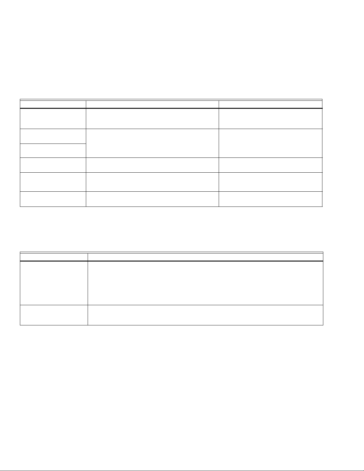
Table 1. Recommended Wire Sizes and Part Numbers.
Application Recommended Wire Size Recommended Part Numbers
Line Voltage Terminals
14, 16, or 18 AWG (0.75, 1.5 or 2.5 mm
2
) copper
TTW60C, THW75C, THHN90C.
conductor, 600 volt insulation, moisture-resistant
wire.
Keyboard Display
Module KDM
a
22 AWG (0.34 mm2) two-wire twisted pair with
ground, or five-wire.
Belden 8723 shielded cable or
equivalent.
Data ControlBus™
Module
Remote Reset Module
22 AWG (0.34 mm2) two-wire twisted pair, insulated
—
for low voltage.
Communications
Interface ControlBus™
Module
13 Vdc full wave rectified
transformer power input
a
The KDM, Data ControlBus™ Module (for remote mounting or communications) or Communication Interface Control-
22 AWG (0.34 mm2) two-wire twisted pair with
ground.
18 AWG (0.75 mm
2
) wire insulated for voltages and
temperatures for given application.
Belden 8723 shielded cable or
equivalent.
TTW60C, THW75C, THHN90C.
Bus™ Module must be wired in a daisy chain configuration, (1(a)-1(a), 2(b)-2(b), 3(c)-3(c)). The order of interconnection
of all the devices listed above is not important. Be aware that modules on the closest and farthest end of the daisy chain
configuration string require a 120 ohm (1/4 watt minimum) resistor termination across terminals 1 and 2 of the electrical connectors for connections over 100 feet (30.5 meters).
Table 2. Recommended Grounding Practices.
Ground Type Recommended Practice
Earth ground (subbase
and relay module).
1. Use to provide a connection between the subbase and the control panel of the equip-
ment. Earth ground must be capable of conducting enough current to blow the 15A
fuse (or breaker) in the event of an internal short circuit.
2. Use wide straps or brackets to provide minimum length, maximum surface area ground
conductors. If a leadwire is required, use 14 AWG copper wire.
3. Make sure that mechanically tightened joints along the ground path are free of non-
conductive coatings and protected against corrosion on mating surfaces.
Signal ground (Keyboard
Display Module, Data
Use the shield of the signal wire to ground the device to the signal ground terminals—3(c)—of
each device. Connect the shield at both ends of the daisy chain to earth ground.
ControlBus Module™
32-00157-03 4
Page 5

RM7890A,B/EC7890A,B 7800 SERIES RELAY MODULES
Table 3. Terminal Ratings.
Terminal Number Description Ratings (RM7890A,B,C) Ratings (EC7890A,B)
G Flame Sensor Ground — —
Earth G
Earth Ground
a
——
L2(N) Line Voltage Common — —
3 Line Voltage Supply (L1) 120 Vac (+10%/-15%), 50 or
60 Hz (±10%).
b
220-240 Vac (=10%/-15%), 50 or
60 Hz (±10%).
4 Alarm 120 Vac, 1A pilot duty. 220-240 Vac, 1A pilot duty.
5Unused — —
6 Burner Controller and Limits 120 Vac, 8A run, 43A inrush. 220-240 Vac, 5A (maximum).
7Unused — —
8 Pilot Valve/Ignition.
9Main Fuel Valve.
10 Ignition
120 Vac.
120 Vac.
120 Vac, 4.5A ignition.
c
220-240 Vac, 4A at P.F. = 0.5, 20A
inrush.
c
220-240 Vac, 4A at P.F. = 0.5, 20A
inrush.
c
220-240 Vac, 4A at P.F. = 0.2.
F(11) Flame Sensor 60 to 220 Vac, current limited. 60 to 220 Vac, current limited.
12 to 21 Unused. — —
22 Shutter 120 Vac, 0.5A (RM7890B).
a
The RM/EC7890 must have an earth ground providing a connection between the subbase and the control panel or the
220-240 Vac (EC7890B only).
d
equipment. The earth ground wire must be capable of conducting the current to blow the 15A fuse (or breaker) in event
of an internal short circuit. The RM/EC7890 needs a low impedance ground connection to the equipment frame which,
in turn, needs a low impedance connection to earth ground. For a ground path to be low impedance at RF frequencies,
the connection must be made with minimum length conductors having maximum surface areas. Wide straps or
brackets rather than leadwires are preferred. Be careful to verify that mechanically tightened joints along the ground
path, such as pipe or conduit threads or surfaces held together with fasteners, are free of nonconductive coatings and
are protected against mating surface corrosion.
b
2000 VA maximum connected load to the RM/EC7890 Assembly.
c
See Tables 4 and 5 for device load combinations.
d
Requires 220-240 to 120 Vac, 10 Va minimum stepdown transformer to drive the shutter. Not applicable for
C7061A1020, C7061A1079 or C7061F1003.
Table 4. Combinations for Terminals 8, 9, and 10.
Pilot Fuel 8 Main 9 Ignition 10
CFNo Load
BFNo Load
FFA
FNo LoadA
DF A
DDA
DNo LoadA
AB C D F
4.5A ignition 50 VA Pilot Duty
plus 4.5A ignition.
180 VA ignition plus motor
valves with: 660 VA inrush,
360 VA open, 250 VA hold.
5 32-00157-03
2A Pilot Duty. 65 VA Pilot Duty plus motor
valves with: 3850 VA inrush,
700 VA Open, 250 VA hold.
Page 6

RM7890A,B/EC7890A,B 7800 SERIES RELAY MODULES
WARNING
CAUTION
WARNING
Final Wiring Check
1. Check the power supply circuit. The voltage and
frequency tolerance must match those of the
RM/EC7890. A separate power supply circuit can be
required for the RM/EC7890. Add the required
disconnect means and overload protection.
2. Check all wiring circuits and complete the Static
Checkout in Table 7 before installing the
RM/EC7890 on the subbase.
3. Install the relay module.
4. Restore the panel power.
STATIC CHECKOUT
After checking all wiring, perform this checkout before
installing the RM/EC7890 on the subbase. These tests
verify the Q7800 Wiring Subbase is wired correctly, and
the external controllers, limits, interlocks, actuators,
valves, transformers, motors and other devices are
operating properly.
Explosion Hazard.
Can cause serious injury, death or equipment
damage.
1. Close all manual fuel shutoff valve(s) before
starting these tests.
2. Use extreme care while testing the system. Line
voltage is present on most terminal connections
when power is on.
3. Open the master switch before installing or
removing a jumper on the subbase.
4. Before continuing to the next test, be sure to
remove test jumper(s) used in the previous test.
5. Replace all limits and interlocks that are not
operating properly. Do not bypass limits and
interlocks.
Equipment Recommended
1. Voltmeter (1M ohm/volt minimum sensitivity) set on
the 0 to 300 Vac scale.
2. Two jumper wires, No. 14 wire, insulated, 12 in.
(304.8 mm) long with insulated alligator clips at
both ends. Note that an ammeter can be used in
place of a jumper to confirm current draw of loads.
(ignition, pilot valve and main valve).
General Instructions
1. Perform all applicable tests listed in the Static
Checkout, Table 6, in the order listed.
2. Make sure all manual fuel shutoff valves are closed.
3. For each test, open the master switch and install the
jumper wires between the subbase wiring terminals
listed in the Test Jumpers column.
4. Close the master switch before observing the opera-
tion.
5. Read the voltage between the subbase wiring termi-
nals listed in the Voltmeter column.
6. If there is no voltage or the operation is abnormal,
check the circuits and external devices as described
in the last column.
7. Check all wiring for proper connections, tight termi-
nal screws, and appropriate wire and wiring techniques.
8. Replace all damaged or incorrectly sized wires.
9. Replace faulty controllers, limits, interlocks, actua-
tors, valves, transformers, motors and other devices,
as required.
10. Make sure normal operation is obtained for each
required test before continuing the checkout.
11. After completing each test, be sure to remove the
test jumper(s).
Explosion Hazard.
Can cause serious injury or death.
Be sure all manual fuel shutoff valves are closed.
Equipment Damage Hazard.
Can cause equipment damage or equipment
failure.
Do not perform a dielectric test with the
RM/EC7890 installed. Internal surge protectors
break down and conduct a current, causing the
RM/EC7890 to fail the dielectric test or possibly
destroy the internal lightning and high current
protection.
32-00157-03 6
IMPORTANT
Low fuel pressure limits, if used, could be open.
Bypass them with jumpers for the remaining static
tests (if required).
Page 7

RM7890A,B/EC7890A,B 7800 SERIES RELAY MODULES
CAUTION
CONFIGURATION
JUMPERS
MICROCOMPUTER
RESET
PUSHBUTTON
STATUS LEDs
SAFETY RELAY
CIRCUIT
POWER SUPPLY
OPTIONAL KEYBOARD
DISPLAY MODULE
PLUG-IN
FLAME
AMPLIFIER
RELAY
DRIVE
CIRCUIT
CONTROL
POWER
TEST
JACK
REMOTE
RESET
DDL
DDL
COMMUNICATIONS
IGNITION
PILOT
MAIN VALVE
INDICATES FEEDBACK SENSING
TO RELAY STATUS FEEDBACK
AND LINE VOLT INPUTS
FIELD WIRING
INTERNAL WIRING
1K
RELAY
STATUS
FEEDBACK
AND LINE
VOLTAGE
INPUTS
LIMITS CONTROLLER
1K1
2K2
FLAME SIGNAL
TEST
RS485
1
2
3
L1
(HOT)
L2
N. O.
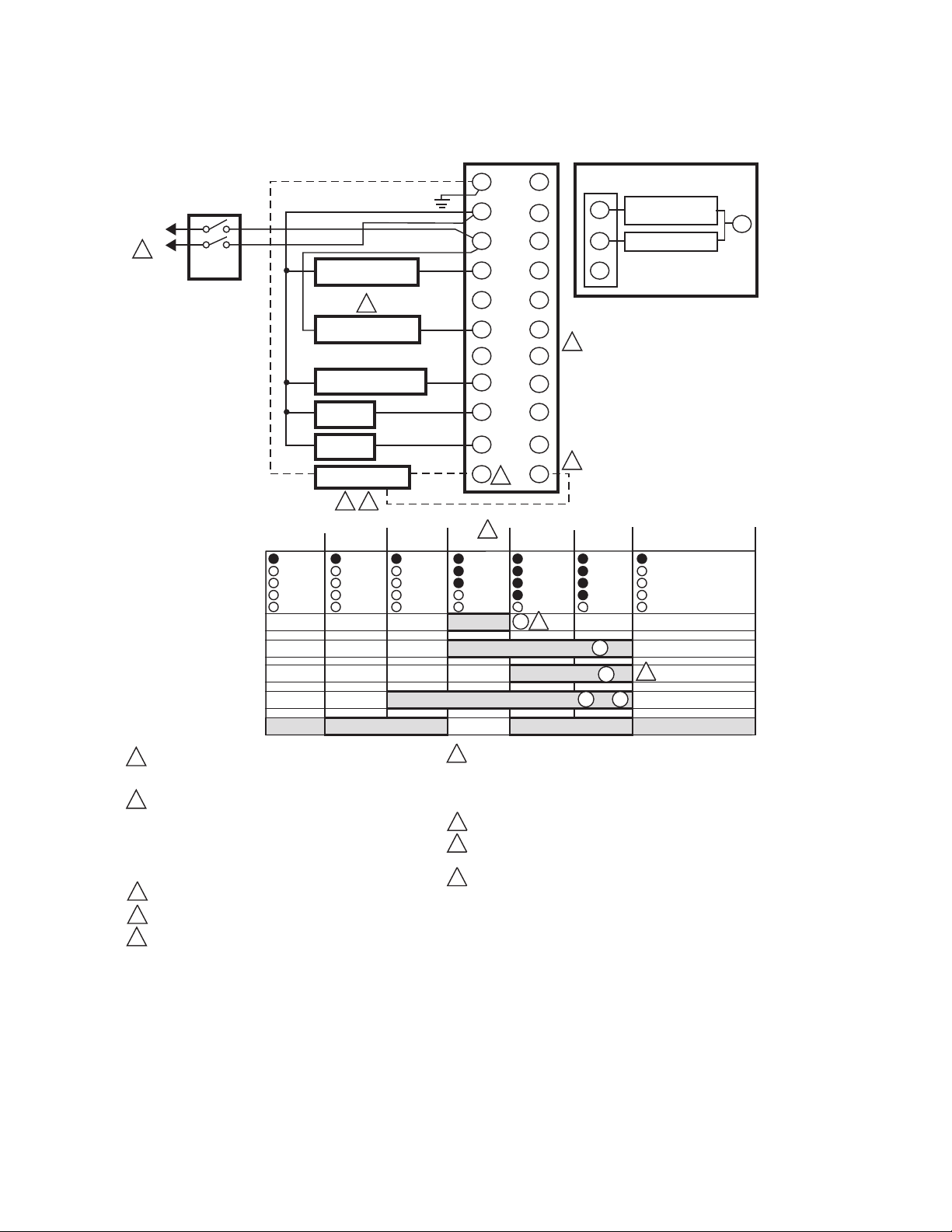
NUMBERS IN CIRCLES ARE RELAY MODULE
TERMINAL NUMBERS.
PROVIDE DISCONNECT MEANS AND
OVERLOAD PROTECTION AS REQUIRED.
120 VAC, 50/60 HZ (RM7890); 220-240 VAC,
50/60 HZ (EC7890) POWER SUPPLY.
EC7890 REQUIRES A 220/240 VAC TO 120 VAC,
10VA, STEPDOWN TRANSFORMER (NOT
SUPPLIED) WHEN USING C7012E, F; C7061A,
AND C7076A FLAME DETECTORS. NOT APPLICABLE
FOR C7061A1020, C7061A1079, C7061F1003
3
6
5K1
4K1
2K1
10
8
9
4K
3K
2K
F
G
22
ALARM
3K1
4
L2
M11586A
F
RM7890C
1
2
2
1
3
3
Table 5. Sta tic C heckout.
Tes t
No. Test Jumpers Voltmeter Normal Operation
If Operation is Abnormal, Check the Items
Listed Below
1 — 3-L2 Line Voltage. 1. Master switch.
2. Power connected to the master switch.
3. Overload protection (fuse, circuit breaker,
etc.) has not opened the power line.
2 — 6-L2 Line Voltage. 1. Limits.
2. Burner control.
3 3-10 — Ignition spark (if ignition
transformer is connected to
terminal 10).
4 3-8 — 1. Ignition spark (if ignition
transformer is connected to
terminal 8).
2. Automatic pilot valve opens (if
connected to terminal 8 or main
valve if DSI application).
NOTE: Refer to wiring diagram
1. Watch for spark or listen for buzz.
a. Ignition electrodes are clean
b. Ignition transformer is okay.
1. Watch for spark or listen for buzz:
a. Ignition electrodes are clean.
b. Ignition transformer is okay.
2. Listen for click or feel head of valve for
activation:
a. Actuator, if used.
b. Pilot valve.
of system being tested.
5 3-9 — Automatic fuel valve(s) opens. (If
using direct spark ignition, check
the second stage fuel valve(s).)
Same as test number 4. If using direct spark
ignition, check the first stage fuel valve(s)
instead of the pilot valve.
6 3-4 — Alarm (if used) turns on. 1. Alarm.
FINAL
Equipment Damage Hazard.
Can cause serious equipment damage.
After completing these tests, open the master switch, remove all test jumpers from the subbase terminals,
and remove any bypass jumpers from the low fuel pressure limits to prevent equipment damage.
7 32-00157-03
Fig. 1. Internal block diagram of the RM/EC7890.
Page 8
RM7890A,B/EC7890A,B 7800 SERIES RELAY MODULES
G
L2
3
5
6
7
8
9
10
F
(L1)
13
14
15
16
17
18
19
20
21
22
12
IGNITION
BURNER
CONTROLLER/LIMITS
LINE VOLTAGE
ALARM
INTERMITTENT
PILOT/IGNITION
FLAME DETECTOR
120V, 50/60 HZ (RM7890) 220-240, 50/60 HZ (EC7890) POWER
SUPPLY. PROVIDE DISCONNECT MEANS AND OVERLOAD
PROTECTION AS REQUIRED.
INSTALL A LINE VOLTAGE CONTROLLER IN SERIES WITH THE
LIMITS. IF USING A LOW VOLTAGE CONTROLLER IS
DESIRABLE, INSTALL AN EXTERNAL RELAY WITH THE N.O.
CONTACTS IN SERIES WITH THE LIMITS. THE LOW VOLTAGE
RELAY COIL WILL BE IN THE LOW VOLTAGE CONTROLLER
CIRCUIT. NOTE THAT IT MAY BE NECESSARY TO PROVIDE
AN EXTERNAL LOW VOLTAGE TRANSFORMER.
DO NOT CONNECT ANY WIRES TO UNUSED TERMINALS.
TERMINAL 22 IS ONLY ON THE RM/EC7890B.
WHEN USING RM/EC7890A OR B; INSTALL AN EXTERNAL
RELAY TO SWITCH THE F LEAD. THE RELAY MUST HAVE
GOLD-CLAD OR GOLD-FLASH CONTACTS AND A LINE
VOLTAGE COIL. POWER THE RELAY COIL FROM THE Q7800
SUBBASE TERMINAL 8. CONNECT THE RELAY CONTACTS
BETWEEN THE F LEAD OF THE DETECTOR AND THE F
TERMINAL OF THE Q7800 SUBBASE.
MASTER
SWITCH
L1
(HOT)
L2
Q7800
4
POWER
00
LED
DISPLAY
OPERATING
CONTROLLER
AND LIMITS
BURNER
START
FLAME
SIGNAL
INITIATE
ALARM
POWER
STANDBY
POWER POWER
PILOT
FLAME
MAIN
PFEP
4 OR 10 SEC
PILOT
FLAME
MAIN
POWER
RUN
STANDBY
4/10
IGNITION
INTERMITTENT PILOT
MAIN VALVE
LIMITS AND BURNER CONTROL CLOSED
9
8
10
3
6
TO
00
POWER
SAFE-
START
ALARM
S S C
SAFE START CHECK
FLAME PROVING
1
2
5
1
3
4
5
2
7
MAIN FUEL
VALVE(S)
3
4
USING EC7890, A 220-240 VAC TO 120 VAC, 10 VA MINIMUM
STEP-DOWN TRANSFORMER (NOT PROVIDED) MUST BE
USED TO DRIVE THE SHUTTER (C7012E,F; C7061; C7076A,D
DETECTORS). NOT APPLICABLE FOR C7061A1020, C7061A1079,
C7061F1003
SEE FLAME DETECTOR SPECIFICATION FOR CORRECT WIRING.
RM7890A1031 PFEP IS 30 SECONDS FIXED. RM7890B1030 PFEP IS
10 SECONDS FIXED.
MAIN FUEL VALVE IS ENERGIZED AND IGNITION (TERMINAL 10) IS
TURNED OFF DURING PFEP ONCE FLAME IS PROVEN.
POWER
PILOT
FLAME
MAIN
ALARM
MFEP
20
6
6
FOR DIRECT SPART IGNITION
(OIL OR GAS)
8
9
10
IGNITION
TRANSFORMER
MAIN VALVE
L2
9
9
7
8
9
EXCEPTIONS:
RM7890A1031/A2031 HAS A FIXED 30 SECOND PFEP
RM7890A1031/A2031 HAS A FIXED 30 SECOND PFEP
RM7890B1030/B2030 HAS A FIXED 10 SECOND PFEP
RM7890A1064/A2064, RM7890B1055/B2055 AND EC7890B1028/B202
JR1 INTACT – 10 SECOND FIXED PFEP, IGNITION
(TERMINAL 10) SHUTS OFF AT 6 SECONDS.
JR1 CLIPPED – 4 SECONDS FIXED PFEP, IGNITION
(TERMINAL 10) SHUTS OFF AT 2 SECONDS.
8
Fig. 2. Wiring subbase and operating sequence chart for RM/EC7890.
32-00157-03 8
Page 9
RM7890A,B/EC7890A,B 7800 SERIES RELAY MODULES
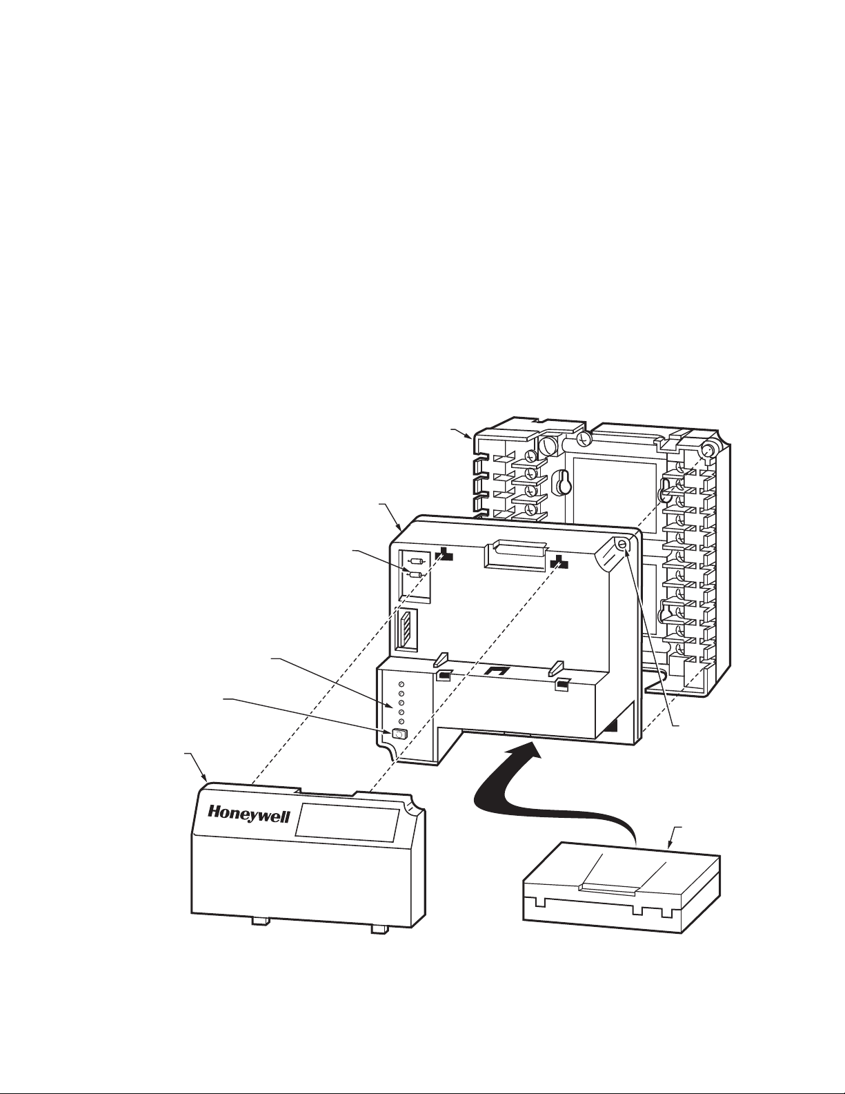
Mounting RM/EC7890 Relay Module
1. Mount the RM/EC7890 vertically on the Q7800
Subbase, or mount horizontally with the knife blade
terminals pointing down. When mounted on the
Q7800A, the RM/EC7890 must be in an electrical
enclosure.
2. When mounting in an electrical enclosure, provide
adequate clearance for servicing, installation and
removal of the RM/EC7890, KDM, flame amplifier,
flame amplifier signal voltage probes, electrical
signal voltage probes, and electrical connections.
a. Allow an additional two inches (51 mm) below
the RM/EC7890 for flame amplifier mounting.
b. Allow an optional three-inch (76 mm) minimum
to both sides of the RM/EC7890 for electrical
signal voltage probes.
RELAY
MODULE
WIRING
SUBBASE
3. Make sure no subbase wiring is projecting beyond
the terminal blocks. Tuck in wiring against the back
of the subbase so it does not interfere with the knife
blade terminals or bifurcated contacts.
IMPORTANT
Install the RM/EC7890 with a plug-in motion
rather than a hinge action.
4. Mount the RM/EC7890 by aligning the four L-
shaped corner guides and knife blade terminals with
the bifurcated contacts on the wiring subbase and
securely tightening the two screws without
deforming the plastic.
Mounting Other System Components (Fig. 3)
Refer to the applicable specifications for mounting other
system components.
Q7800B2003/U SUBBASE SHOWN
HONEYWELL
DUST
COVER
RESET
BUTTON
SEQUENCE
STATUS
LED PANEL
CONFIGURATION
JUMPERS
B
URNE
R
CONTROL
POWER
PIL
OT
MAIN
F
L
AME
AL
A
R
RE
S
M
E
T
CAPTIVE
MOUNTING
SCREW
FLAME
AMPLIFIER
Fig. 3. RM/EC7890 Relay Module exploded view.
9 32-00157-03
Page 10

RM7890A,B/EC7890A,B 7800 SERIES RELAY MODULES
PRINCIPAL TECHNICAL FEATURES
The RM/EC7890 provides all customary flame safeguard
functions as well as significant advancements in safety,
annunciation, and system diagnostics.
Safety Shutdown (Lockout) Occurs if:
1. INITIATE PERIOD
a. AC line power errors occurred, see Operation.
b. Configuration jumpers have been changed (after
200 hours).
c. Four minute INITIATE period has been exceeded.
2. STANDBY PERIOD
a. Flame signal is present after 240 seconds.
b. Ignition/intermittent pilot valve terminal is ener-
gized.
c. Internal system fault occurred.
d. Main valve terminal is energized.
e. 3.0 second (2.0 seconds for RM7890A1064/A2064,
RM7890B1055/B2055 and
EC7890B1028/B2028) Flame Failure Response
Time (FFRT) Amplifier is installed and configuration
jumper is selected for relight (see Table 3).
3. SAFE START CHECK
a. Ignition/intermittent pilot valve terminal is ener-
gized.
b. Internal system fault occurred.
c. Main valve terminal is energized.
4. PILOT FLAME ESTABLISHING PERIOD (PFEP)
a. Ignition/intermittent pilot valve terminal is not
energized.
b. Internal system fault occurred.
c. Main valve terminal is energized.
d. No flame present at end of PFEP.
5. RUN PERIOD
a. Ignition terminal is energized.
b. Internal system fault occurred.
c. Main valve terminal is not energized.
d. No flame present and configuration jumper is
selected for lockout.
e. Pilot valve terminal is not energized.
OPERATION
Sequence of Operation
The RM/EC7890 has the operating sequences listed
below; see Fig. 2. The RM/EC7890 LED provide positive
visual indication of the program sequence: POWER,
PILOT, FLAME, MAIN and ALARM.
Initiate
The RM/EC7890 enters the INITIATE sequence when the
relay module is powered. The RM/EC7890 can also enter
the INITIATE sequence if the relay module verifies voltage
fluctuations of +10/-15% or frequency fluctuations of
±10% during any part of the operating sequence. The
INITIATE sequence lasts for ten seconds unless the
voltage or frequency tolerances are not met. When the
tolerances are not met, a hold condition is initiated and is
displayed on the optional KDM for at least five seconds.
When the tolerances are met, the INITIATE sequence
restarts. If the condition is not corrected and the hold
condition exists for four minutes, the RM/EC7890 locks
out. Causes for hold conditions in the INITIATE sequence:
a. AC line dropout detection.
b. AC line noise that can prevent a sufficient read-
ing of the line voltage inputs.
c. Brownouts caused by a low line voltage.
NOTE: If a 3.0 second flame failure response amplifier is
installed (2.0 seconds for RM7890A1064/A2064,
RM7890B1055/B2055 and EC7890B1028/B2028)
and configuration jumper JR2 is intact, the
RM/EC7890 locks out. JR2 must be clipped.
Standby
The RM/EC7890 is ready to start an operating sequence
when the operating control input (terminal 6) recognizes a
call for heat. The burner switch, limits, operating limit
control and all microcomputer monitored circuits must be
in the correct state for the RM/EC7890 to continue into
the Safe Start Check.
Normal Start-Up Safe Start Check
The RM/EC7890 verifies that a flame or flame simulating
condition does not exist and proceeds into the Ignition
Trial. If a flame or flame simulating condition is present,
the RM/EC7890 remains in the STANDBY period.
Ignition Trials
a. Pilot Flame Establishing Period (PFEP):
(1) The pilot valve and ignition transformer, ter-
minals 8 and 10, are energized. The
RM/EC7890 has an intermittent pilot valve,
terminal 8.
(2) Flame must be proven by the end of the four-
or ten-second PFEP (30 seconds for
RM7890A1031/A2031) or a safety shutdown
occurs.
(3) Once flame is proven, the ignition, terminal
10, is de-energized and the main valve, terminal 9, is energized.
(a)The RM7890B1030/B2030 finishes the 4-
or 10-second PFEP before the main valve is
energized.
(b)The RM7890A1064/A2064 and
RM7890B1055/B2055 with JR1 intact
completes 10 second PFEP, shutting off
ignition (Terminal 10) at 6 seconds. When
the JR1 clipped these devices complete a 4
second PFEP, shutting off ignition (terminal 10) at 2 seconds.
Run
The RM/EC7890 is now in RUN and remains in RUN until
the controller input, terminal 6, opens, indicating that the
demand is satisfied or a limit has opened.
32-00157-03 10
Page 11

RM7890A,B/EC7890A,B 7800 SERIES RELAY MODULES
SELECTABLE CONFIGURATION JUMPERS
1 2
1
2
JR2 REMOVED FROM RM7890C.
RM7890A1031/A2031 PFEP IS FIXED AT 30 SECONDS, IF
JR1 IS INTACT OR CLIPPED.
M11589A
SETTINGS AND ADJUSTMENTS
Selectable Site-Configurable Jumpers
The RM/EC7890 has two site-configurable jumper
options, see Fig. 4 and Table 7. If necessary, clip the siteconfigurable jumpers with side cutters and remove the
resistors from the relay module.
Table 6. Site-Configurable Jumper Options.
Jumper
Number Description Intact Clipped
Pilot Flame
Establishing Period
a
JR1
(PFEP)
JR2 Flame Failure Action
a
Not Applicable for RM7890A1031/A2031 (30 second
10
seconds
Relight
c
b
4
seconds
Lockout
PFEP). JR1 removed.
b
30 seconds for RM7890A1031/A2031.
c
The Relight feature (JR2 intact) requires a 0.8 second
FFRT Flame Amplifier. The EC/RM7890 locks out and
indicates a Fault 46 if a 3.0 second (2.0 second for
RM7890A1031/B2031, RM7890B1055/B2055 and
EC7890B1028/B2028) FFRT is used and jumper JR2 is
not clipped and removed.
d
Clipping and removing a site-configurable jumper after
200 hours of operation results in a hard lockout, code
110.
e
For RM7890A1064/B2064, RM7890B1055/B2055 and
EC7890B1028/B2028:
Intact—Fixed 10 seconds PFEP , Ignition (terminal 10)
shuts off at 6 seconds.
Clipped—Fixed 4 seconds PFEP, Ignition (terminal 10)
shuts off at 2 seconds.
d
b
Fig. 4. Selectable site-configurable jumpers.
SERVICE NOTE
Clipping and removing a site-configurable jumper
enhances the level of safety. If using three-second
amplifier, site-configurable jumper JR2 must be clipped
and removed. If not removed, an F46 Lockout occurs.
SAFETY AND SECURITY
Physical device protection
Device shall be accessible to authorized personnel only –
Installation on publicly accessible places is not
recommended as this could lead to unwanted and
potentially unsafe changes to device (wiring,
configuration, etc).
It is recommended to lock the device in an enclosed
cabinet with access allowed only to approved and trained
personnel. Also, it is strongly advised to keep all the wiring
of device physically secure.
Physical protection of the device is applied via Run/Test
switch label/seal. It is intended to prevent and detect
unauthorized access.
Modbus & DDL Interface security
Any conducts critical to device functionality (DDL,
Modbus lines etc.) shall be physically protected (installed
outside public access) since they could be damaged or
tampered-with by unauthorized people, either
accidentally or for purpose.
Modbus RS-485 & DDL protocols do not support security
features. For DDL interface - only DDL devices shall be
connected to the Burner Controller DDL line.
License agreement
Copying and reverse engineering is prohibited by the law.
11 32-00157-03
Page 12

RM7890A,B/EC7890A,B 7800 SERIES RELAY MODULES
For More Information
The Honeywell Thermal Solutions family of products includes
Honeywell Combustion Safety, Eclipse, Exothermics, Hauck,
Kromschröder and Maxon. To learn more about our products,
visit ThermalSolutions.honeywell.com or contact your
Honeywell Sales Engineer.
Honeywell Process Solutions
Honeywell Thermal Solutions (HTS)
1250 West Sam Houston Parkway
South Houston, TX 77042
ThermalSolutions.honeywell.com
® U.S. Registered Trademark
© 2020 Honeywell International Inc.
32-00157-03 M.S. 04-20
Printed in United States
 Loading...