

Honeywell RM7838B1021, RM7838B2021, RM7838C1012, RM7838C2012 Installation Instructions Manual
RM7838B, RM7838C
7800 SERIES Relay Modules
INSTALLATION INSTRUCTIONS
APPLICATION
The Honeywell RM7838B,C is a microprocessor based
integrated burner control for industrial process
semiautomatically fired gas, oil, coal or combination fuel
single burner modulation applications and available Valve
Proving System (VPS) feature. The RM7838B,C System
consists of a relay module, wiring subbase, keyboard
display module (KDM), amplifier, and purge card. Options
include personal computer interface, Data ControlBus
Module™, remote display mounting, first-out expanded
annunciator and Modbus™ network capable.
Functions provided by the RM7838B,C include automatic
modulated High Fire and Low Fire proven Purge, then the
sequence stops, waiting for a Start Switch input, flame
supervision, system status indication, system or selfdiagnostics and troubleshooting.
The RM7838C differs from the RM7838B as follows:
1. Alarms only on Safety Shutdown.
2. Has 15-second MFEP.
3. Requires ST7800C Purge Timer.
This document covers the following 7800 Series Relay
Modules:
RM7838B1021
RM7838B2021
RM7838C1012
RM7838C2012
This document provides installation and static checkout
instructions. Other applicable publications are:
Form Number Description
32-00110 S7800A2142 4-line LCD Keyboard
32-00166 204729A/C KDM NEMA4 Covers for
65-0084 Q7800A,B 22-Terminal Wiring
65-0089 ST7800A,C Plug-In Purge Timer
65-0288 S7800A1142 Keyboard Display
65-0091 S7810A Data ControlBus Module™
65-0095 S7820 Remote Reset Module Product
65-0097 221729 Dust Cover Installation
65-0101 S7830 Expanded Annunciator Product
3
2-00235
65-0131 221818A Extension Cable Assembly
65-0229 7800 Series Relay Modules Checkout
65-0295 50023821-001/2 NEMA4 Covers for
Display Module Product Data
4-line LCD KDM
Subbase Product Data.
Installation Instructions.
Module Product Data.
Product Data.
Data.
Instructions.
Data.
R7824, R7847, R7848, R7849, R7861,
R7862, R7886 Flame Amplifiers for
the 7800 Series Product Data.
Product Data.
and Troubleshooting Product Data.
2-line Keyboard Display Module
Contents
APPLICATION................................................................................ 1
SPECIFICATIONS......................................................................... 2
INSTALLATION ................................................................................... 2
FINAL WIRING CHECK .............................................................. 7
STATIC CHECKOUT............................................................................ 8
V
ALVE PROVING SYSTEM ................................................................ 11
P
RINCIPAL TECHNICAL FEATURES ................................................ 17
PERATION........................................................................................ 19
O
S
ETTINGS AND ADJUSTMENTS ....................................................... 21
T
ROUBLESHOOTING ......................................................................... 22
SAFETY AND SECURITY............................................................ 27
SIL
Capable
3
32-00211-01
RM7838B, RM7838C 7800 SERIES RELAY MODULES
WARNING
MV1
MV2
VP
SW.
M22660B
OUTLET
INLET
1
CAUTION: VALVE ENERGIZING TIMING IS BASED ON VALVE OPENING
TIMES OF 13 SECONDS MAXIMUM.
− FOR VALVES WITH TIMINGS GREATER THAN 13
SECONDS - A BYPASS SOLENOID (RATED AS A SAFETY
SHUTOFF VALVE) VALVE (1/4”, 120 VAC) IS REQUIRED TO
OBTAIN THE PROPER TEST PRESSURES.
− THE BYPASS VALVE WILL BE WIRED IN PARALLEL TO THE
VALVE IT IS BYPASSING (TERMINAL 9 FOR MV1 OR
TERMINAL 17 FOR MV2).
1
The RM7838B1021 and RM7838C1012 Relay Modules
offer VPS, thus they differ in the following manner from
the RM7838B1013 and RM7838C1004:
1. Terminal 16 changes from Pilot Valve Hold Input to
Valve Proving Switch Input.
2. Terminal 17 changes from Manual Valve Open Input
to Main Valve 2 Output.
3. JR3-Deferred or Immediate Function is replaced
with Fan On for VPS.
4. Blinkum fault annunciation on safety shutdown
(power LED blinks a fault code).
5. Built-in features set up only using the S7800A1142
Keyboard Display Module.
a. Valve Proving System.
b. Programmable Postpurge.
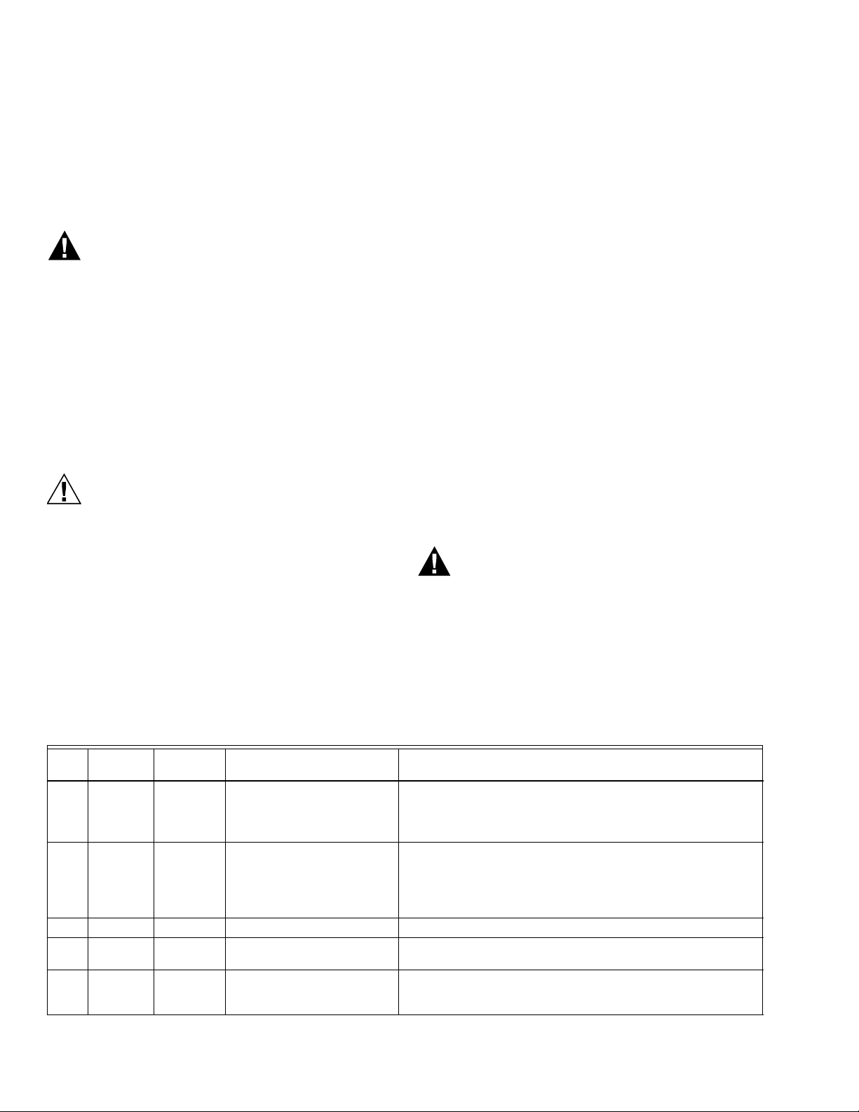
At commissioning time, the Valve Proving System may be
scheduled to occur at one of five different times:
• Never—Device default as received—Valve proving does
not occur.
• Before—Before Start input; concurrent with Prepurge.
• After—Valve proving occurs after the Run state, (Stop
Switch pushed) before the device goes to Standby.
(Concurrent with Postpurge, if selected.)
• Both—Valve proving occurs at both times Before and
After, noted above.
• Split—The main valve 1 (MV1) (high pressure) seat test
is performed at the Before time and the main valve 2
(MV2) (low pressure) seat test is performed during the
After time.
The following assumptions apply when using the
RM7838B1021 or RM7838C1012 Valve Proving testing:
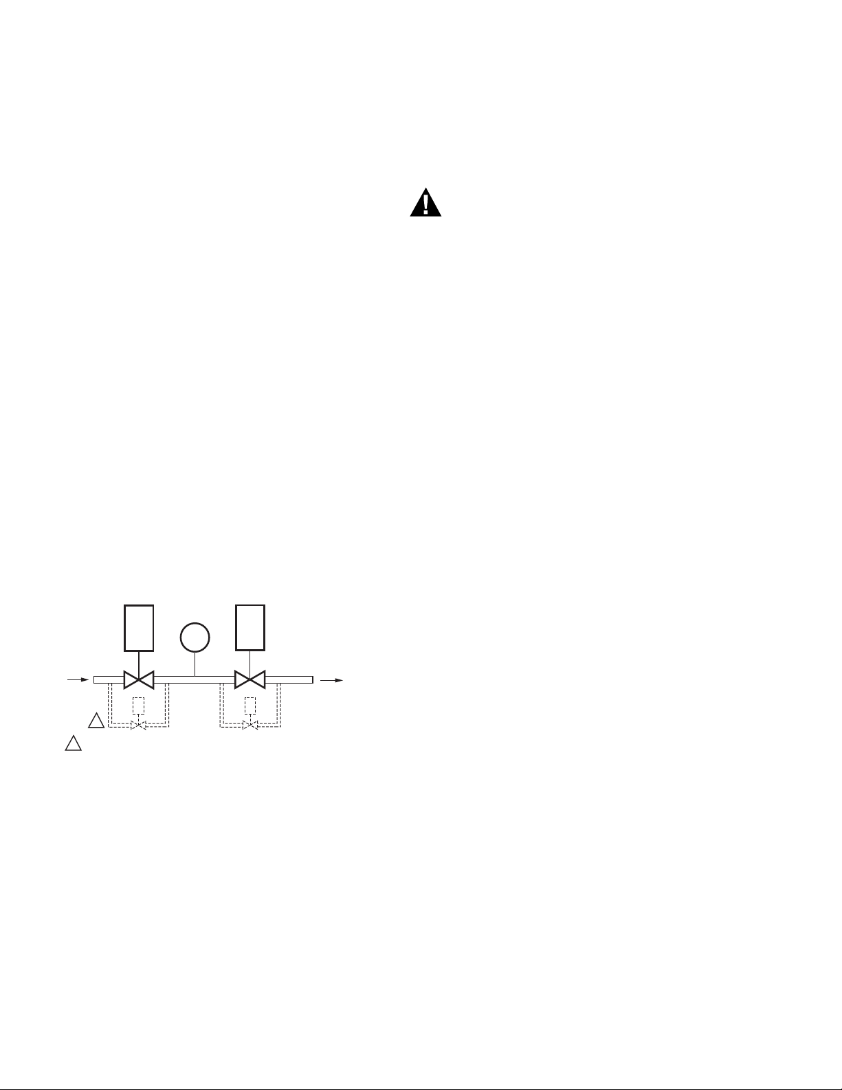
Fig. 1. The valve proving system.
MV1— Wired to terminal 9. It is located in the most
upstream position of the main gas valve train.
VPS—Valve Proving Switch: Setpoint at 1/2 of Main Valve
inlet pressure.
MV2—Wired to terminal 17. It is the main valve located
closest to the burner.
The Proof of Closure Switch (PII—Pre-Ignition Interlock)
for terminal 20 can be installed on MV1, MV2, or both
valves.
Explosion Hazard.
Can cause severe injury, death or property
damage.
Leaking gas valves can result in fire or explosion.
The Valve Proving System is designed to detect
such leaks. A valve proving test time that is too
short may allow unacceptable leaks to go
undetected. Use the procedure in Appendix A to
select sufficient valve test times to detect any
unacceptable leak.
SPECIFICATIONS
Electrical Ratings (See Table 4):
Voltage and Frequency: 120 Vac (+10/-15%),
50/60 Hz (±10%).
Power Dissipation:
RM7838B,C: 10W maximum.
Maximum Total Connected Load: 2000 VA.
Fusing Total Connected Load: 15A maximum, fast blow
type SC or equivalent.
Environmental Ratings:
Ambient Temperature:
Operating: -40°F to 140°F (-40°C to 60°C).
Storage: -40°F to 150°F (-40°C to +66°C).
Humidity: 85% relative humidity continuous, noncon-
densing.
Vibration: 0.5G environment.
SIL 3 Capable:
SIL 3 Capable in a properly designed Safety Instrumented
System. See form number 65-0312-04 for Certificate
Agreement.
Approvals:
Underwriters Laboratories Inc. Listed: File No. MP268, Vol.
30. UL 37260730-2-5 / CSA C22.2 No. 60730-2-5.
Factory Mutual Approved: Report No. 1V9A0.AF.
Swiss Re (formerly Industrial Risk Insurers): Acceptable.
Federal Communications Commission: Part 15, Class B,
Emissions.
Exida: IEC 61508:2010 Parts 1-7, SIL 3 capable.
Control Safety Devices: Acceptable CSD-1
EAC Russia
IMPORTANT
A Flame Detection System is required for
operation and must be ordered separately. Select
the applicable Flame Signal Amplifier and
matching Flame Detector in form 65-0109.
32-00211—01 2

INSTALLATION
WARNING
WARNING
When Installing this Product...
1. Read these instructions carefully. Failure to follow
them could damage the product or cause a
hazardous condition.
2. Check the ratings given in the instructions and
marked on the product to make sure the product is
suitable for the application.
3. Installer must be a trained, experienced, flame
safeguard service technician.
4. After installation is complete, check out the product
operation as provided in these instructions.
Explosion or Fire Hazard.
Can cause severe injury, death or property
damage.
To prevent possible hazardous burner operation,
verify safety requirements each time a control is
installed on a burner.
RM7838B, RM7838C 7800 SERIES RELAY MODULES
9. This equipment generates, uses and can radiate
radio frequency energy and, if not installed and
used in accordance with the instructions, can
cause interference with radio communications. It
has been tested and found to comply with the
limits for a
Class B computing device of Part 15 of FCC rules,
which are designed to provide reasonable
protection against such interference when
operated in a commercial environment. Operation
of this equipment in a residential area can cause
interference; in which case, the users, at their own
expense, may be required to take whatever
measures are required to correct this interference.
10. This digital apparatus does not exceed the Class B
limits for radio noise for digital apparatus set out
in the Radio Interference Regulations of the Canadian Department of Communications.
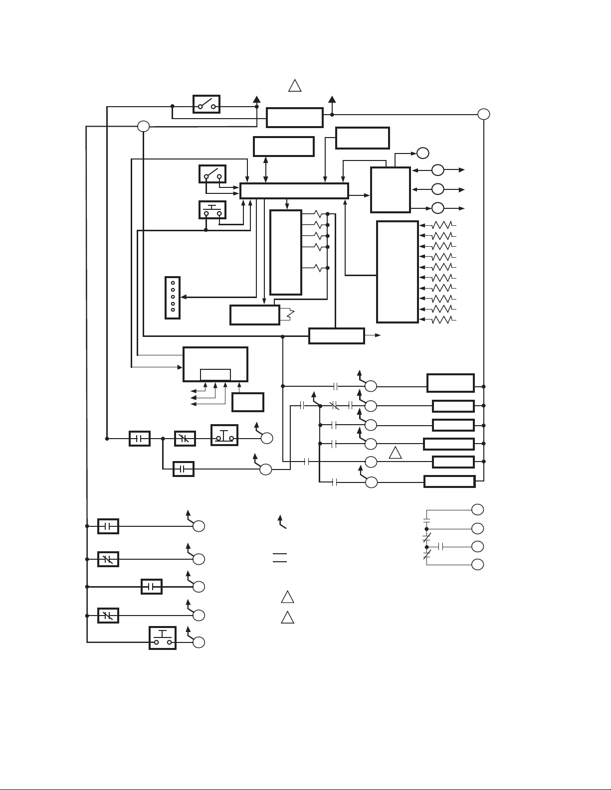
See Fig. 3 for the internal block diagram of the
RM7838B,C Relay Module.
Location
Electrical Shock Hazard.
Can cause severe injury, death or equipment
damage.
Disconnect the power supply before beginning
installation. More than one power supply
disconnect can be required.
IMPORTANT
1. Wiring connections for the relay modules are
unique; refer to Fig. 4 or the appropriate Specifications for proper subbase wiring.
2. Wiring must comply with all applicable codes,
ordinances and regulations.
3. Wiring must comply with NEC Class 1
(Line Voltage) wiring.
4. Loads connected to the RM7838B,C must not
exceed those listed on the RM7838B,C label or the
Specifications; see Table 4.
5. Limits and interlocks must be rated to simultaneously carry and break current to the ignition transformer, pilot valve, and main fuel valve(s).
6. All external timers must be listed or component
recognized by authorities who have proper
jurisdiction.
7. For on-off gas-fired systems, some authorities
who have jurisdiction prohibit the wiring of any
limit or operating contacts in series between the
flame safeguard control and the main fuel valve(s).
8. Two Flame Detectors can be connected in parallel
with the exception of Infrared Flame Detectors
(C7015, C7915) Ultraviolet Flame Detectors
(C7927, C7961), and Visible Light Detector
(C7962).
Humidity
Install the relay module where the relative humidity never
reaches the saturation point. The relay module is designed
to operate in a maximum 85% relative humidity
continuous, noncondensing, moisture environment.
Condensing moisture can cause a safety shutdown.
Vibration
Do not install the relay module where it can be subjected
to vibration in excess of 0.5G continuous maximum
vibration.
Weather
The relay module is not designed to be weather tight.
When installed outdoors, protect the relay module in an
approved weather-tight enclosure.
Mounting Wiring Subbase
1. Mount the subbase in any position except
horizontally with the bifurcated contacts pointing
down. The standard vertical position is
recommended.
2. Select a location on a wall, burner or electrical panel.
The Q7800 can be mounted directly in the control
cabinet; be sure to allow adequate clearance for
service, installation, access or removal of the
RM7838B,C, Expanded Annunciator, KDM, flame
amplifier, flame amplifier signal voltage probes,
Run/Test Switch, electrical signal voltage probes
and electrical field connections.
3. For surface mounting, use the back of the subbase
as a template to mark the four screw locations, then
drill the pilot holes.
4. Securely mount the subbase using four no. 6 screws.
3 32-00211—01

RM7838B, RM7838C 7800 SERIES RELAY MODULES
WARNING
Relay Module and Subbase Compatiblity
NOTE: There are several different subbase models that
can be purchased. It is important to note which
subbase is compatible with the relay module
when purchasing new, repair or replacement
parts.
Series 1000 Relay Modules
All relay product codes that start with a 1 (example:
RM7840G1
Q7800A1003/U and Q7800A1005/U.
Series 2000 Relay Modules
All relay product codes that start with a 2 (example:
RM7840G2
Q7800A2003/U and Q7800A2005/U.
Subbase Compatibility
Any Relay Module in the 1000 Series with a Software
Revision level number starting with a "5" or greater will be
compatible with all subbase models both installed and
newly purchased. This includes (Q7800A1005/U,
Q7800B1003/U), and the 2000 Series subbases
(Q7800A2005/U, Q7800B2003/U).
See Fig. 2 for Software Revision Level number location on
the label (located on the rear of the relay module).
014/U) can be used with existing subbase
014/U) must be used with subbase
Any relay module in the new 2000 series will only be able
to be installed on subbase Q7800A2005/U,
Q7800B2003/U and will not be backward compatible with
any Q7800A1003/U and Q7800A1005/U subbases
already installed in the field.
Fig. 2. Software revision location.
IMPORTANT
Make sure to check the relay model number and
the software revision level on the relay.
• If you attempt to place a 2000 series relay on a noncompatible 1000 series subbase, you will receive an
error code of 101. This indicates that you must a)
change out the subbase to a Q7800A2003/U or
Q7800A2005/U or b) choose a compatible 1000 series
relay module.
Wiring Subbase
Electrical Shock Hazard.
Can cause serious personal injury, death or
equipment damage.
Disconnect the power supply before beginning
installation. More than one power supply
disconnect may be required.
Application Recommended Wire Size Recommended Part Numbers
Line voltage terminals
KDM
Data ControlBus
Module™
Remote Reset Module
13 Vdc full wave rectified
transformer power input.
1. Refer to Fig. 4 for proper subbase wiring.
2. For proper remote wiring of the KDM, refer to the
KDM Specifications (65-0288), Data ControlBus
Module™ (65-0091) or Extension Cable Assembly
(65-0131).
3. Make sure all wiring complies with all applicable
electrical codes, ordinances and regulations. Wiring,
where required, must comply with NEC, Class 1
(Line Voltage) wiring.
4. See Table 1 for recommended wire size and type.
Table 1. Recommended Wire Sizes and Part Numbers.
14, 16 or 18 AWG (0.75, 1.5 or 2.5 mm2) copper
conductor, 600 volt insulation, moisture-resistant
wire.
2
22 AWG (0.34 mm
ground, or five-wire.
22 AWG (0.34 mm2) two-wire twisted pair with
ground, or five-wire.
22 AWG (0.34 mm2) two-wire twisted pair, insulated
for low voltage.
18 AWG (0.75 mm
temperatures for given application.
) two-wire twisted pair with
2
) wire insulated for voltages and
TTW60C, THW75C, THHN90C.
Belden 8723 shielded cable or
equivalent.
Belden 8723 shielded cable or
equivalent.
—
TTW60C, THW75C, THHN90C.
The KDM or Data ControlBus Module™ (for remote
mounting or communications) must be wired in a daisy
chain configuration,
32-00211—01 4
1(a)-1(a), 2(b)-2(b), 3(c)-3(c). The order of interconnection
of all the devices listed above is not important. Be aware
that modules on the closest and farthest end of the daisy

RM7838B, RM7838C 7800 SERIES RELAY MODULES
chain configuration string require a 120 ohm (1/4 watt
minimum) resistor termination across terminals 1 and 2 of
the electrical connectors, for connections over 100 feet
(31 meters).
5. See Table 2 for recommended grounding practices.
6. Use recommended wire routing of leadwires:
a. Do not run high voltage ignition transformer
wires in the same conduit with the flame
detector, Data ControlBus Module™, or Remote
Reset Module wiring.
b. Do not route flame detector, Data ControlBus
Module™, or Remote Reset Module leadwires in
conduit with line voltage circuits.
c. Enclose flame detector leadwires without armor
cable in metal cable or conduit.
7. Follow directions in flame detector, Data ControlBus
Module™, or Remote Reset Module
Instructions.KDM: Because the KDM is powered
from a low voltage, energy limited source, mount it
outside of a control panel if it can be protected from
mechanical damage.
Table 2. Recommended Grounding Practices.
Ground Type Recommended Practice
Earth Ground (Subbase and relay
module)
1. Use to provide a connection between the subbase and the control panel of
the equipment. Earth ground must be capable of conducting enough current
to blow the 15A fast blow, type SC or equivalent, fuse (or breaker) in the event
of an internal short circuit.
2. Use wide straps or brackets to provide minimum length, maximum surface
area ground conductors. If a lead wire must be used, use 14 AWG copper
wire.
3. Make sure that mechanically-tightened joints along the ground path are free
of nonconductive coatings and protected against corrosion on mating
surfaces.
Signal Ground (KDM, Data
ControlBus Module™).
Use the shield of the signal wire to ground the device to the signal ground terminal
3(c) of each device. Connect the shield at both ends of the daisy chain to earth
ground.
NOTE: Use a separate 13 Vdc power supply any time
more than two Data ControlBus Modules™ or
KDM are used or are placed more than 100 feet
(31 meters) from the relay module.
8. Use maximum wire lengths:
a. RM7838B,C leadwires—300 feet (91 meters) to
terminal inputs (Control, Preignition Interlock,
Running/Lockout Interlock, High Purge Switch
and Low Fire Switch).
b. Flame Detector leadwires—limited by the flame
signal strength.
c. Remote Reset leadwires—1000 feet (305 meters)
to a Remote Reset push button.
d. Data ControlBus Module™—depends on the
number of system modules connected, the noise
conditions and the cable used. The maximum
length of all Data ControlBus Module™
interconnecting wire is 4000 feet (1219 meters).
9. Make sure loads do not exceed the terminal ratings.
Refer to the label on the RM7838B,C or to the ratings
in Table 4.
5 32-00211—01
RM7838B, RM7838C 7800 SERIES RELAY MODULES
CONFIGURATION
JUMPERS
MICROCOMPUTER
RESET
PUSHBUTTON
RUN/TEST
SWITCH
STATUS LED
PLUG-IN PURGE
TIMER CARD
SAFETY RELAY
CIRCUIT
POWER SUPPLY
KEYBOARD
DISPLAY MODULE
HIGH PURGE
COMMON
MODULATE
LOW FIRE
PLUG-IN
FLAME
AMPLIFIER
RELAY
DRIVE
CIRCUIT
CONTROL
POWER
TEST
JACK
REMOTE
RESET
DDL
DDL
COMMUNICATIONS
INDICATES FEEDBACK SENSING
OF RELAY CONTACT STATUS
AND LINE VOLT INPUTS
FIELD WIRING
INTERNAL WIRING
IGNITION
PILOT
MAIN VALVE 1
1K
RELAY
STATUS
FEEDBACK
AND LINE
VOLTAGE
INPUTS
LIMITS
PREIGNITION
INTERLOCK
1K1 2K1 5K1
8K1
8K2
9K1
9K2
120 Vac
50/60 HZ
FLAME SIGNAL
TEST
PROVIDE DISCONNECT MEANS AND
OVERLOAD PROTECTION AS REQUIRED.
AN ALARM SILENCING SWITCH MAY BE
NEEDED FOR RM7838B.
RS485
1
2
3
L1
(HOT) L2
4
6
7
4K1
2K2
10
8
9
7K
5K
4K
3K
2K
F
G
22
1
6K1
5
ALARM
3K1
3
L2
12
13
15
14
M22661B
2
1
RECIRCULATING
BLOWER
STOP SWITCH
RECIRCULATING
AFS
COMBUSTION
AIR BLOWER
16
18
19
20
21
LOCKOUT INTERLOCKS
AND COMBUSTION AIR
BLOWER SWITCHES
VALVE PROVING
SWITCH
LOW START
SWITCH
HIGH PURGE
RATE SWITCH
START SWITCH
BURNER CONTROL
MAIN VALVE 2
7K
17
2
32-00211—01 6
Fig. 3. Internal block diagram of RM7838B,C.
RM7838B, RM7838C 7800 SERIES RELAY MODULES
M32334
G
L2
3
5
6
7
8
9
10
11
4
(L1)
13
14
17
18
19
20
21
22
12
16
15
LIMITS
MAIN FUEL
VALVE 1
INTERMITTENT/
INTERRUPTED
PILOT/IGNITION
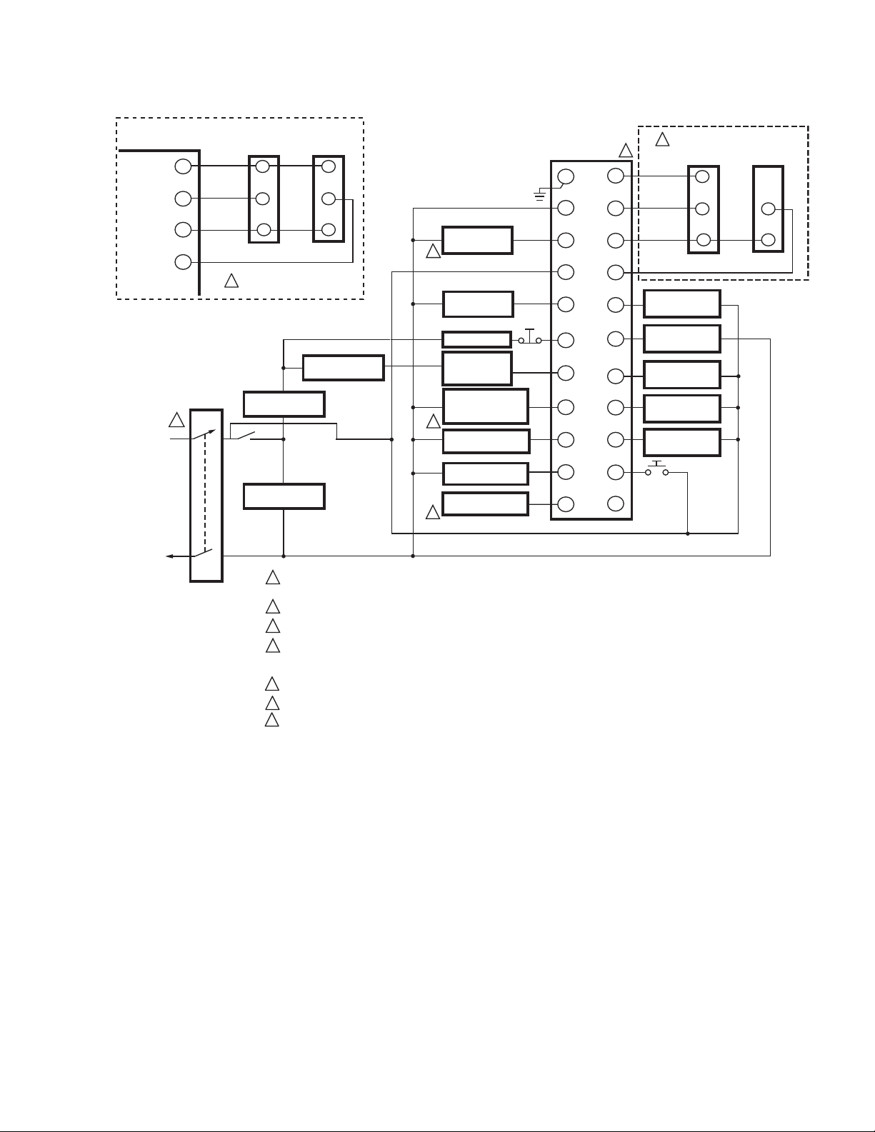
120V, 50/60 HZ POWER SUPPLY. PROVIDE DISCONNECT MEANS AND OVERLOAD PROTECTION (15 AMP TYPE
SC FUSE OR EQUIVALENT FAST BLOW FUSE) AS REQUIRED.
DO NOT CONNECT WIRES TO UNUSED TERMINALS.
SEE FLAME DETECTOR SPECIFICATIONS FOR CORRECT DETECTOR WIRING.
JR-2 CLIPPED INTERRUPTED PILOT
RM7838B - 10 SECOND MFEP
RM7838C - 15 SECOND MFEP.
ALARM SILENCING MAY BE NEEDED FOR RM7838B.
ALTERNATE WIRING FOR 4-20 MA SYSTEM.
LINE VOLTAGE
ALARM
1
HIGH FIRE
COMMON
LOW FIRE
MODULATE
F
_
+
M7284
FIRING RATE
MOTOR
+
4-20 mA
OUTPUT
CONTROLLER
VALVE PROVING
SWITCH
MAIN FUEL
VALVE 2
LOW FIRE
START SWITCH
HIGH PURGE
RATE SWITCH
PREIGNITION
INTERLOCK (POC)
IGNITION
RECIRCULATING
AIRFLOW SWITCH
COMBUSTION
AIR FAN
2
3
4
3
4
2
5
5
_
FLAME DETECTOR
START
SWITCH
COMBUSTION
AIRFLOW
SWITCH
STOP
SWITCH
RECIRCULATING
BLOWER
BURNER
CONTROL
6
1
13
14
12
15
Q7800 SUBBASE
HIGH FIRE
COMMON
LOW FIRE
MODULATE
B
R
W
SERIES 90
FIRING RATE
MOTOR
B
R
W
SERIES 90
CONTROLLER
6
7
7
ALTERNATE WIRING FOR SERIES 90 CONTROL CIRCUIT.
LOCKOUT
INTERLOCK
L1
L2
FINAL WIRING CHECK
1. Check the power supply circuit. The voltage and
frequency tolerance must match those of the
RM7838B,C. (A separate power supply circuit may
be required for the RM7838B,C.)
2. Add the required disconnect means and overload
protection.
3. Check all wiring circuits and complete the static
checkout in Table 3 before installing the RM7838B,C
Fig. 4. Wiring subbase for RM7838B,C.
on the subbase.
4. Install the relay module.
5. Restore power to the panel.
7 32-00211—01
RM7838B, RM7838C 7800 SERIES RELAY MODULES
WARNING
CAUTION
WARNING
STATIC CHECKOUT
After checking all wiring, perform this checkout before
installing the RM7838B,C on the subbase. These tests
verify the Q7800 Wiring Subbase is wired correctly, and
the external controllers, limits, interlocks, actuators,
valves, transformers, motors and other devices are
operating properly.
Explosion and Electrical Shock Hazards.
Can cause serious injury, death or equipment
damage.
Close all manual fuel shutoff valve(s) before
starting these tests.
Use extreme care while testing the system. Line
voltage is present on most terminal connections
when power is on.
Open the master switch before installing or removing a
jumper on the subbase. Before continuing to the next test,
be sure to remove test jumper(s) used in the previous test.
Replace all limits and interlocks that are not operating
properly. Do not bypass limits and interlocks.
Electrical Hazard.
Can cause equipment damage.
Do not perform a dielectric test with the
RM7838B,C installed. Internal surge protectors
break down and conduct current, causing dielectric
test failure and destruction of the internal lightning
and high current protection.
Equipment Recommended
1. Voltmeter (1M ohm/volt minimum sensitivity) set on
the 0-300 Vac scale.
2. Two jumper wires; using No. 14 wire, insulated, 12 in.
(304.8 mm) long with insulated alligator clips at
both ends.
3. Ammeter can be used to verify loads (e.g. valves,
ignition transformers) connected to the wiring subbase.
General Instructions
1. Perform all applicable tests listed in the Static
Checkout, Table 3, in the order listed.
2. Make sure all manual fuel shutoff valves are closed.
3. Perform only those tests designated for the specific
RM7838B,C model being tested.
4. For each test, open the master switch and install the
jumper wires between the subbase wiring terminals
listed in the Test Jumpers column.
5. Close the master switch before observing operation.
6. Read the voltage between the subbase wiring termi-
nals listed in the Voltmeter column.
7. If there is no voltage or the operation is abnormal,
check the circuits and external devices as described
in the last column.
8. Check all wiring for correct connections, tight terminal screws, correct wire, and proper wiring techniques. Replace all damaged or incorrectly sized
wires.
9. Replace faulty controllers, limits, interlocks, actuators, valves, transformers, motors and other devices,
as required.
10. Make sure normal operation is obtained for each
required test before continuing the checkout.
11. After completing each test, be sure to remove the
test jumper(s).
Explosion Hazard.
Can cause serious injury or death.
Make sure all manual fuel shutoff valves are closed.
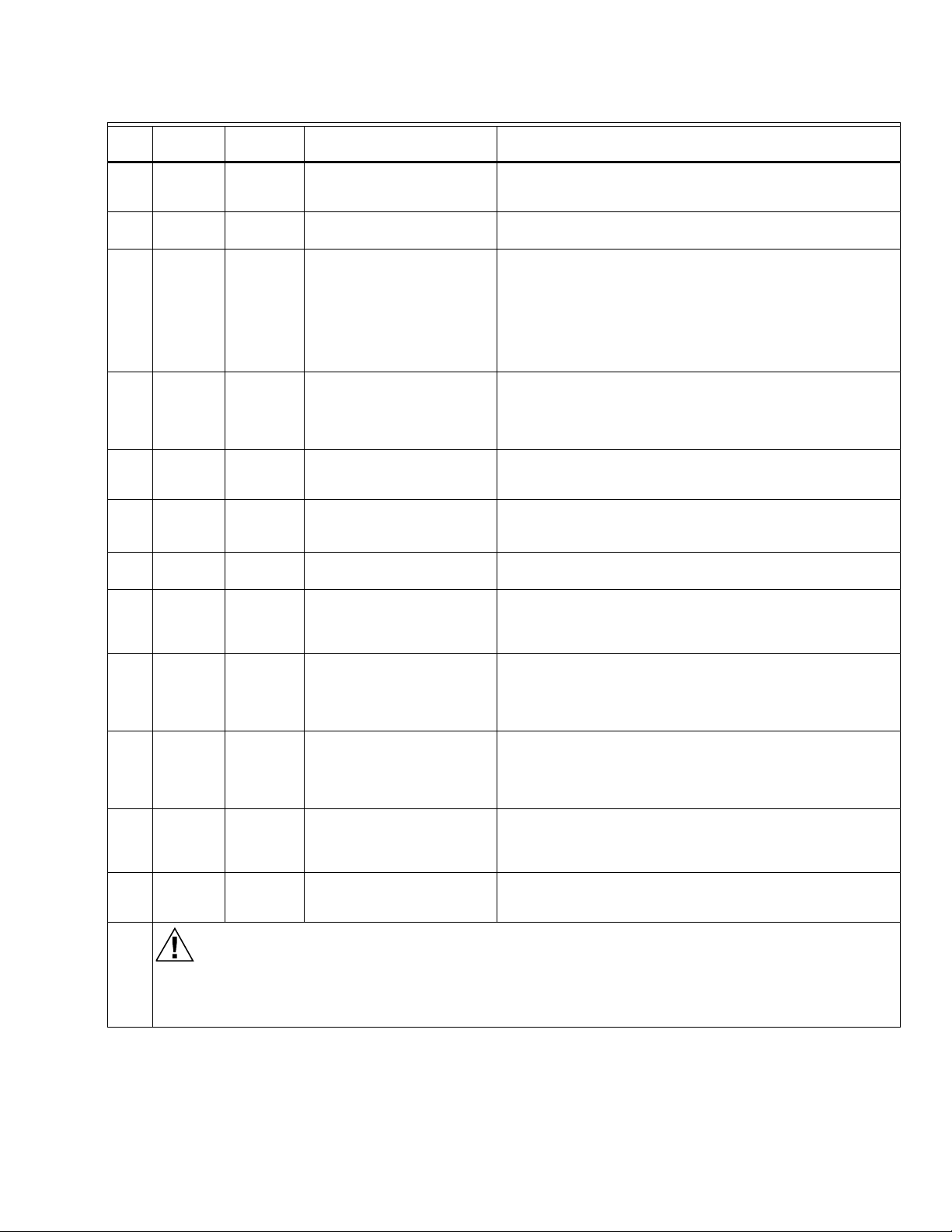
Table 3. Static Checkout.
Tes t
No.
1 None 4-L2 Line voltage at terminal 4. 1. Master Switch.
2 None 6-L2 Close burner control.
2a None 4-20 Line voltage at terminal 20. Preignition Interlock.
2b None 4-16 Line voltage at terminal 16. Valve Proving Switch.
3 None 21-L2 With test 2 still running,
32-00211—01 8
Tes t
Jumpers Voltmeter Normal Operation If Operation is Abnormal, Check These Items
2. Power Connected to the Master Switch.
3. Overload protection (fuse, circuit breaker, etc) has not
opened the power line.
Recirculating exhaust
blower fan starts, then line
voltage at terminal 6.
press Start Switch. 120 Vac
is present at terminal 21.
1. Recirculating/exhaust blower fan.
2. Limits.
3. Stop Switch.
4. Burner Control.
5. Recirculating AFS.
Start Switch.
RM7838B, RM7838C 7800 SERIES RELAY MODULES
CAUTION
Table 3. Static Checkout. (Continued)
Tes t
No.
4 None 6-L2 Push and hold Stop Switch.
5 4-3 None Alarm (if used) turns on. 1. Alarm.
6 4-5 7-L2 Close burner control.
7 4-8 None Automatic pilot valve opens.
8 4-9 None Automatic main fuel valves
9 4-10 None Ignition spark (if ignition
10 4-17 None Line voltage at terminal 17. 1. Listen for click or feel valve head for actuation of main
11 12-13 18-L2 Firing rate motor drives
12 12-13 19-L2 Firing rate motor reaches
13 13-14 19-L2 Firing rate motor leaves
14 13-14 18-L2 Firing rate motor drives to
15 13-15 None Adjust firing rate control
Final
Tes t
Jumpers Voltmeter Normal Operation If Operation is Abnormal, Check These Items
No voltage present at
terminal 6.
Recirculating/exhaust
blower fan starts, then line
voltage is present at
terminal 6.
1. Combustion air fan starts.
2. Line voltage at terminal 7
within 10 seconds.
First stage valve
(DSI application only).
Ignition spark (if ignition
transformer connected).
open. (DSI checks optional
second state fuel valve.)
transformer connected to
terminal 10.
open; zero volts at terminal
18 after motor leaves Low
Fire position.
High Purge Rate position;
120 Vac at terminal 19
when High Purge Rate
Switch closes.
High Purge Rate Position;
zero Vac at terminal 19
when High Purge Rate
Switch opens.
Low Purge Rate position;
120 Vac at terminal 18
when switch closes.
and watch tracking action of
the firing rate motor.
Stop Switch.
2. Alarm Silencing Switch.
1. Combustion air fan circuit:
a. Manual switch on air fan motor.
b. Air fan power supply, overload protection, and starter.
2. Combustion Blower Air Flow Switch.
3. Alarm Silencing Switch.
4. Recirculating Air Flow Switch.
1. Listen for click or feel head of valve for activation.
2. Watch for spark or listen for buzz:
a. Ignition electrodes are clean.
b. Ignition transformer is okay.
Listen for and observe operation of the main fuel valve(s)
and actuator(s).
1. Watch for spark or listen for buzz:
a. Ignition electrodes are clean.
b. Ignition transformer is okay.
valve # 2.
1. Low Fire Start Switch.
2. Firing rate motor and transformer.
1. High Purge Rate Switch.
2. Firing rate motor and transformer.
1. High Purge Rate Switch.
2. Firing rate motor and transformer.
1. Low Purge Rate Switch.
2. Firing rate motor and transformer.
1. Firing rate control.
2. Firing rate motor and transformer.
Electrical Hazard.
Can cause equipment damage.
After completing these tests, open the Master Switch and remove all test jumpers from the subbase terminals.
Also remove bypass jumpers from the low fuel pressure limits if used.
9 32-00211—01
 Loading...