

Honeywell RM7838B, RM7838C Installation Instructions Manual

SIL
3
Capable
RM7838B,C
maxon.su
7800 SERIES Relay Module
INSTALLATION INSTRUCTIONS
APPLICATION
The Honeywell RM7838B,C is a microprocessor based
integrated burner control for industrial process modulating
semiautomatically fired gas, oil, coal or combination fuel
single burner applications. The RM7838B,C System consists
of a relay module, wiring subbase, keyboard display module
(KDM), amplifier, and purge card. Options include Data
ControlBus Module™, remote display mounting, and first-out
expanded annunciator.
Functions provided by the RM7838B,C include automatic
modulated High Fire and Low Fire proven Purge, burner pilot
startup with pilot valve hold, a special pilot valve hold from the
Run condition, flame supervision, system status indication,
system or self-diagnostics and troubleshooting.
The RM7838C differs from the RM7838B as follows:
1. Alarms only on Safety Shutdown.
2. Requires ST7800C Purge Timer.
3. C1004 has 15 second MFEP. C1020 has 5 second
MFEP.
This document provides installation and static checkout
instructions. Other applicable publications are:
65-0084: Q7800A,B 22-Terminal Wiring Subbase
Product Data.
65-0089: ST7800A,C Plug-In Purge Timer
Installation Instructions.
65-0090: S7800A Keyboard Display Module
Product Data.
65-0101: S7830 Expanded Annunciator Product
Data.
65-0109: R7824, R7847, R7848, R7849, R7851,
R7852, R7861, R7886 Flame Amplifiers
for the 7800 Series Product Data.
65-0131: 221818A Extension Cable Assembly
Product Data.
65-0229: 7800 Series Relay Modules Checkout and
Troubleshooting Product Data.
65-0249: S7810M ModBus™ Module Product Data.
SPECIFICATIONS
Electrical Ratings (See Table 4):
Voltage and Frequency: 120 Vac (+10/-15%),
50/60 Hz (±10%).
Power Dissipation:
RM7838B,C: 10W maximum.
Maximum Total Connected Load: 2000 VA.
Fusing Total Connected Load: 15A maximum, type SC or
equivalent, fast blow.
Environmental Ratings:
Ambient Temperature:
Operating: -40°F to +140°F (-40°C to +60°C).
Storage: -40°F to +150°F (-40°C to +66°C).
Humidity: 85% relative humidity continuous, noncondensing.
Vibration: 0.5G environment.
SIL 3 Capable:
SIL 3 Capable in a properly designed Safety Instrumented
System. See form number 65-0312 for Certificate Agree-
ment.
Approvals:
Underwriters Laboratories Inc. Listed: File No. MP268, Guide
No. MCCZ.
Canadian Standards Association Certified: LR9S329-3.
Factory Mutual Approved: Report No. 1V9A0.AF.
Swiss Re (formerly Industrial Risk Insurers): Acceptable.
Federal Communications Commission: Part 15, Class B,
Emissions.
Gastec: EN298, Report 115679/4 (RM7838C1020 only)
IMPORTANT
A Flame Detection System is required for operation
and must be ordered separately. Select the
applicable Flame Signal Amplifier and matching
Flame Detector in form 65-0109.
INSTALLATION
When Installing this Product...
1. Read these instructions carefully. Failure to follow
them could damage the product or cause a hazardous
condition.
2. Check the ratings given in the instructions and marked
on the product to make sure the product is suitable for
the application.
3. Installer must be a trained, experienced, flame
safeguard service technician.
4. After installation is complete, check out the product
operation as provided in these instructions.
RM7838C1020 only
66-1094-08

RM7838B,C 7800 SERIES RELAY MODULE
WARNING
WARNING
WARNING
maxon.su
Explosion or Fire Hazard.
Can cause severe personal injury, death or
property damage.
To prevent possible hazardous burner operation, verify
safety requirements each time a control is installed on
a burner.
Electrical Shock Hazard.
Can cause electrical shock or equipment damage.
Disconnect the power supply before beginning
installation. More than one power supply disconnect
can be required.
Location
Humidity
Install the relay module where the relative humidity never
reaches the saturation point. The relay module is designed to
operate in a maximum 85% relative humidity continuous,
noncondensing, moisture environment. Condensing moisture
can cause a safety shutdown.
Vibration
Do not install the relay module where it can be subjected to
vibration in excess of 0.5G continuous maximum vibration.
Weather
The relay module is not designed to be weather tight. When
installed outdoors, protect the relay module in an approved
weather-tight enclosure.
Mounting Wiring Subbase
1. Mount the subbase in any position except horizontally
with the bifurcated contacts pointing down. The
standard vertical position is recommended; any other
position decreases the maximum ambient temperature
rating.
2. Select a location on a wall, burner or electrical panel.
The Q7800 can be mounted directly in the control
cabinet; be sure to allow adequate clearance for
service, installation, access or removal of the
RM7838B,C, Expanded Annunciator, KDM, flame
amplifier, flame amplifier signal voltage probes,
Run/Test Switch, electrical signal voltage probes and
electrical field connections.
3. For surface mounting, use the back of the subbase as a
template to mark the four screw locations; then drill the
pilot holes.
4. Securely mount the subbase using four no. 6 screws.
IMPORTANT
1. Wiring connections for the relay modules are unique;
refer to Fig. 2 and 3 or the appropriate Specifications
for proper subbase wiring.
2. Wiring must comply with all applicable codes,
ordinances and regulations.
3. Wiring must comply with NEC Class 1
(Line Voltage) wiring.
4. Loads connected to the RM7838B,C must not
exceed those listed on the RM7838B,C label or the
Specifications; see Table 4.
5. Limits and interlocks must be rated to simultaneously
carry and break current to the ignition transformer,
pilot valve, and main fuel valve(s).
6. All external timers must be listed or component
recognized by authorities who have proper
jurisdiction.
7. For on-off gas-fired systems, some authorities who
have jurisdiction prohibit the wiring of any limit or
operating contacts in series between the flame
safeguard control and the main fuel valve(s).
8. Two Flame Detectors can be connected in parallel
with the exception of Infrared Flame Detectors
(C7015 and C7915), UV Flame Detectors C7927,
and C7961 and visible light detector C7962.
9. This equipment generates, uses and can radiate
radio frequency energy and, if not installed and used
in accordance with the instructions, can cause
interference with radio communications. It has been
tested and found to comply with the limits for a
Class B computing device of Part 15 of FCC rules,
which are designed to provide reasonable protection
against such interference when operated in a
commercial environment. Operation of this
equipment in a residential area can cause
interference; in which case, the users, at their own
expense, may be required to take whatever
measures are required to correct this interference.
10. This digital apparatus does not exceed the Class B
limits for radio noise for digital apparatus set out in
the Radio Interference Regulations of the Canadian
Department of Communications.
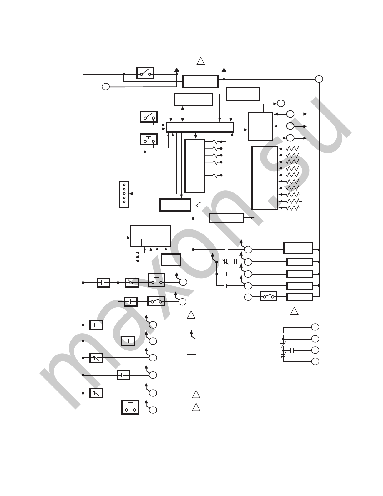
See Fig. 1 for the internal block diagram of the RM7838B,C
Relay Module.
Wiring Subbase
Electrical Shock Hazard.
Can cause serious personal injury, death or
equipment damage.
Disconnect the power supply before beginning
installation. More than one power supply disconnect
may be required.
1. Refer to Fig. 2 or 3 for proper subbase wiring.
2. For proper remote wiring of the KDM, refer to the KDM
Specifications (65-0090), Data ControlBus Module™
(65-0091) or Extension Cable Assembly (65-0131).
3. Make sure all wiring complies with all applicable
electrical codes, ordinances and regulations. Wiring,
where required, must comply with NEC, Class 1
(Line Voltage) wiring.
66-1094—08 2
4. See Table 1 for recommended wire size and type.
maxon.su
RM7838B,C 7800 SERIES RELAY MODULE
4
DDL
COMMUNICATIONS
RECIRCULATING
AFS
LOCKOUT INTERLOCKS
AND COMBUSTION AIR
BLOWER SWITCHES
PILOT VALVE
HOLD SWITCH
LOW START
SWITCH
HIGH PURGE
RATE SWITCH
PREIGNITION
INTERLOCK
BURNER CONTROL
RUN/TEST
SWITCH
RESET
PUSHBUTTON
STATUS LED
KEYBOARD
DDL
MANUAL VALVE
OPEN SWITCH
DISPLAY MODULE
LIMITS
START SWITCH
RS485
1
2
3
STOP SWITCH
1/2 OF DPST
ALARM SILENCING
SWITCH
16
17
18
19
20
21
L1
(HOT) L2
CONFIGURATION
JUMPERS
SAFETY RELAY
CIRCUIT
REMOTE
RESET
1
120 Vac
50/60 HZ
RECIRCULATING
BLOWER
MICROCOMPUTER
RELAY
DRIVE
CIRCUIT
6
7
2
INDICATES FEEDBACK SENSING
OF RELAY CONTACT STATUS
AND LINE VOLT INPUTS
FIELD WIRING
INTERNAL WIRING
PROVIDE DISCONNECT MEANS AND
1
OVERLOAD PROTECTION AS REQUIRED.
2
NOT REQUIRED FOR RM7838C.
PLUG-IN PURGE
TIMER CARD
FLAME SIGNAL
2K
3K
4K
5K
7K
1K
POWER SUPPLY
6K1
1K1 2K1 5K1
4K1
2K2
3K1
TEST
PLUG-IN
FLAME
AMPLIFIER
RELAY
STATUS
FEEDBACK
AND LINE
VOLTAGE
INPUTS
CONTROL
POWER
5
10
8
9
3
1/2 OF DPST
ALARM SILENCING
SWITCH
8K1
8K2
9K2
TEST
JACK
F
G
22
COMBUSTION
AIR BLOWER
IGNITION
PILOT
MAIN VALVE
ALARM
2
HIGH PURGE
COMMON
MODULATE
9K1
LOW FIRE
M5195D
L2
12
13
15
14
Fig. 1. Internal block diagram of RM7838B,C (see Fig. 2 for RM7838C1020); see Fig. 3 and 4 for detailed wiring
instructions.
3 66-1094—08
RM7838B,C 7800 SERIES RELAY MODULE
L1
HOT
N
1
4
2
19
CONFIGURATION
JUMPERS
PLUG-IN PURGE
TIMER CARD
F
G
22
PLUG -IN
FLAM E
A M P L IF IE R
PLUG-IN
FLAME
AMPLIFIER
MICROCOMPUTER
RUN/TEST
SWITCH
RESET
PUSHBUTTON
FLAM E SIGNAL
TEST
JACK
RELAY
DRIVE
CIRCUIT
1K
2K
3K
4K
5K
6K
7K
8K
9K
CONTROL
POWER
POWER SUPPLY
18
20
RELAY
STATUS
FEEDBACK
AND LINE
VOLTAGE
INPUTS
10
8
9
5
3
OPTIONAL KEYBOARD
DISPLAY MODULE
RS485
16
1K
2K2 5K1
4K1
2K1
PV1
MV
3K1
6K1
21
LFS
HFS
PII
3K2
SAFETY RELAY
CIRCUIT
7
COMBUSTION
BLOWER
AL
IGN
AL
DDL
13
15
14
12
HIGH FIRE
COMMON
LOW FIRE
MODULATE
REMOTE
RESET
8K1
8K2
9K2
9K1
INDICATES FEEDBACK SENSING
OF RELAY CONTACT STATUS
AND LINE VOLTAGE INPUTS
RELAY CONTACT OPEN
INTERNAL WIRING
FIELD WIRING
RELAY COIL
RELAY CONTACT CLOSED
DDL
COMMUNICATIONS
1
2
3
5
USER TERMINALS
1
120 VAC, 50/60 Hz POWER SUPPLY.
M13959
STATUS
LEDS
SHUTTER
FG
...
22
COMBUSTION
BLOWER AFS
START
6
RECIRCULATING
BLOWER AFS
RECIRCULATING
BLOWER
L2
STOP
BURNER
CONTROL
maxon.su
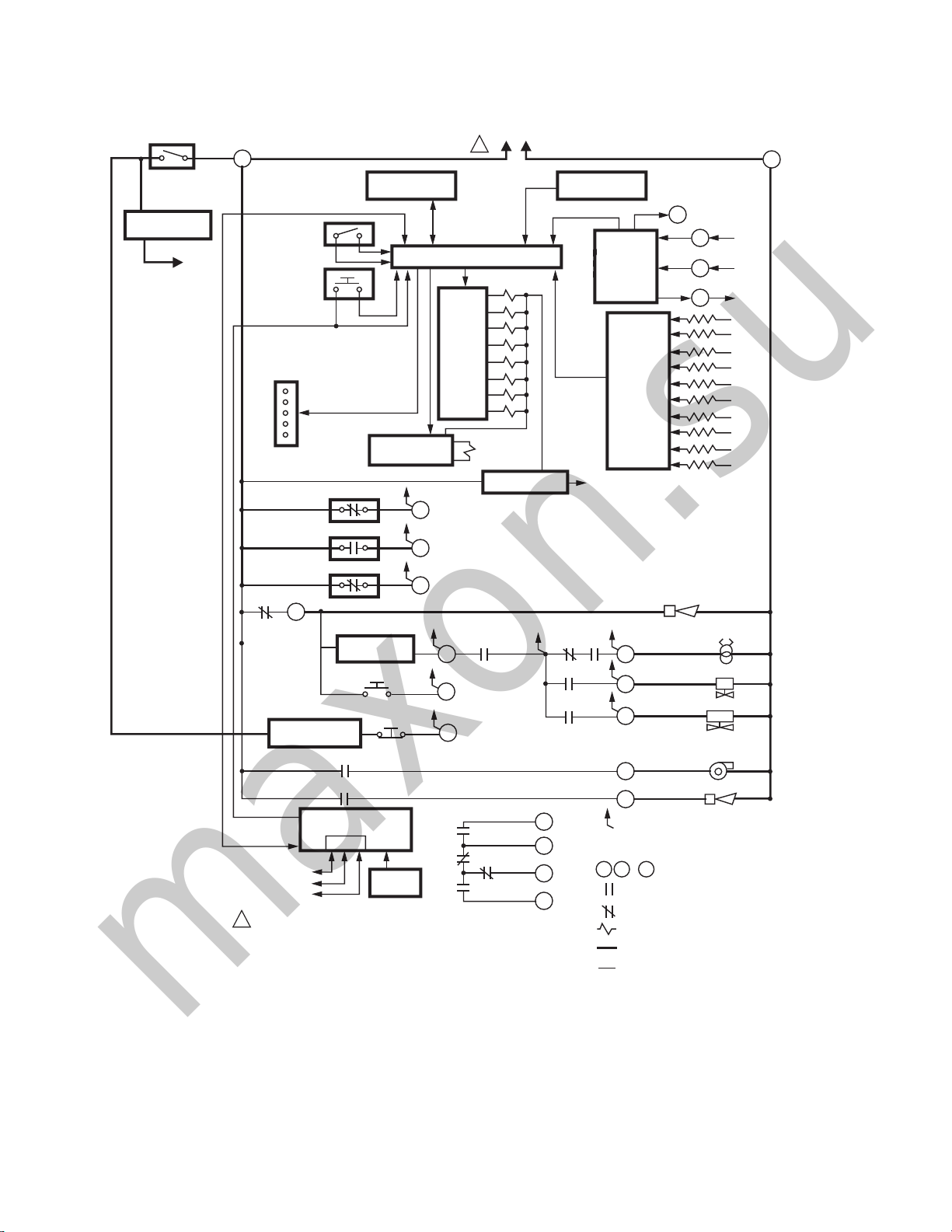
Fig. 2. Internal block diagram of RM7838C1020 (see Fig. 5 for detailed wiring instructions).
66-1094—08 4
RM7838B,C 7800 SERIES RELAY MODULE
maxon.su
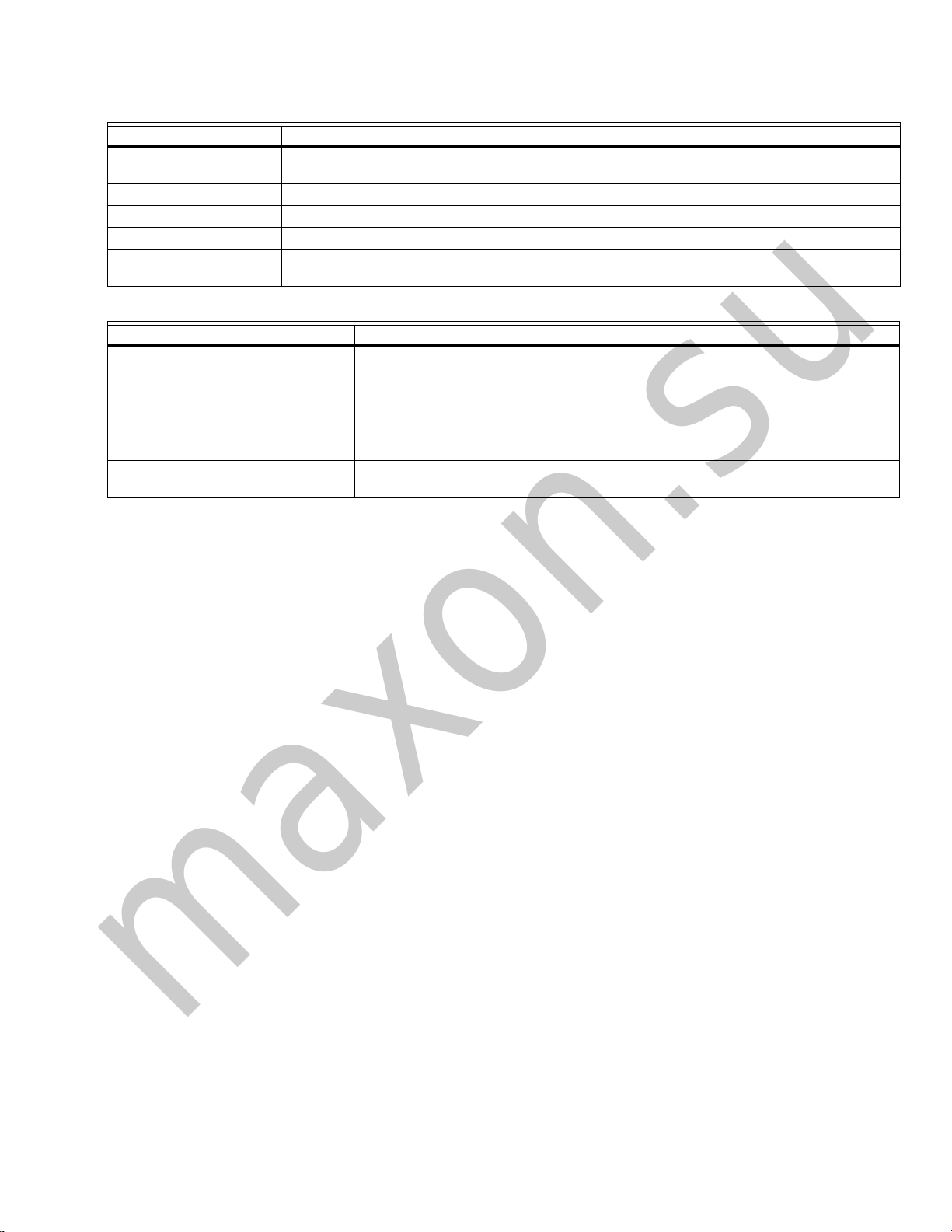
Table 1. Recommended Wire Sizes and Part Numbers.
Application Recommended Wire Size Recommended Part Numbers
Line voltage terminals 14, 16 or 18 AWG copper conductor, 600 volt
KDM 22 AWG two-wire twisted pair with ground, or five-wire. Belden 8723 shielded cable or equivalent.
Data ControlBus Module™ 22 AWG two-wire twisted pair with ground, or five-wire. Belden 8723 shielded cable or equivalent.
Remote Reset Module 22 AWG two-wire twisted pair, insulated for low voltage. —
13 Vdc full wave rectified
transformer power input.
Ground Type Recommended Practice
Earth Ground (Subbase and relay
module)
Signal Ground (KDM, Data ControlBus
Module™
insulation, moisture-resistant wire.
18 AWG wire insulated for voltages and temperatures
for given application.
Table 2. Recommended Grounding Practices.
1. Use to provide a connection between the subbase and the control panel of the
equipment. Earth ground must be capable of conducting enough current to blow
the 15A fuse (or breaker) in the event of an internal short circuit.
2. Use wide straps or brackets to provide minimum length, maximum surface area
ground conductors. If a lead wire must be used, use 14 AWG copper wire.
3. Make sure that mechanically-tightened joints along the ground path are free of
nonconductive coatings and protected against corrosion on mating surfaces.
Use the shield of the signal wire to ground the device to the signal ground terminal 3(c)
of each device. Connect the shield at both ends of the daisy chain to earth ground.
TTW60C, THW75C, THHN90C.
TTW60C, THW75C, THHN90C.
The KDM and Data ControlBus™ Module (for remote
mounting or communications) must be wired in a daisy chain
configuration, 1(a)-1(a), 2(b)-2(b), 3(c)-3(c). The order of
interconnection of all the devices listed above is not important.
Be aware that modules on the closest and farthest end of the
daisy chain configuration string require a 120 ohm (1/4 watt
minimum) resistor termination across terminals 1 and 2 of the
electrical connectors, for connections over 100 feet (31
meters).
4. See Table 2 for recommended grounding practices.
5. Use recommended wire routing of leadwires:
a. Do not run high voltage ignition transformer wires in
the same conduit with the flame detector, Data
ControlBus Module™, or Remote Reset Module
wiring.
b. Do not route flame detector, Data ControlBus
Module™, or Remote Reset Module leadwires in
conduit with line voltage circuits.
c. Enclose flame detector leadwires without armor
cable in metal cable or conduit.
d. Follow directions in flame detector, Data ControlBus
Module™, or Remote Reset Module Instructions.
6. KDM: Because the KDM is powered from a low voltage,
energy limited source, mount it outside of a control
panel if it can be protected from mechanical damage.
NOTE: Use a separate 13 Vdc power supply any time more
than two Data ControlBus Modules™ or KDM are
used or are placed more than 100 feet (31 meters)
from the relay module.
7. Use maximum wire lengths:
a. RM7838B,C leadwires—300 feet (91 meters) to
terminal inputs (Control, Preignition Interlock,
Running/Lockout Interlock, High Purge Switch and
Low Fire Switch).
b. Flame Detector leadwires—limited by the flame
signal strength.
c. Remote Reset leadwires—1000 feet (305 meters) to
a Remote Reset push button.
d. Data ControlBus™ Module—depends on the
number of system modules connected, the noise
conditions and the cable used. The maximum length
of all Data ControlBus™ Module interconnecting
wire is 4000 feet (1219 meters).
8. Make sure loads do not exceed the terminal ratings.
Refer to the label on the RM7838B,C or to the ratings in
Table 4.
FINAL WIRING CHECK
1. Check the power supply circuit. The voltage and fre-
quency tolerance must match those of the RM7838B,C.
(A separate power supply may be required for the
RM7838B,C.)
2. Add the required disconnect means and overload
protection.
3. Check all wiring circuits and complete the static
checkout in Table 3 before installing the RM7838B,C on
the subbase.
4. Install the relay module.
5. Restore power to the panel.
STATIC CHECKOUT
After checking all wiring, perform this checkout before
installing the RM7838B,C on the subbase. These tests verify
the Q7800 Wiring Subbase is wired correctly, and the external
controllers, limits, interlocks, actuators, valves, transformers,
motors and other devices are operating properly.
5 66-1094—08
RM7838B,C 7800 SERIES RELAY MODULE
WARNING
CAUTION
WARNING
maxon.su
Explosion and Electrical Shock Hazards.
Can cause serious injury, death or equipment
damage.
Close all manual fuel shutoff valve(s) before starting
these tests.
Use extreme care while testing the system. Line
voltage is present on most terminal connections when
power is on.
Open the master switch before installing or removing a jumper
on the subbase. Before continuing to the next test, be sure to
remove test jumper(s) used in the previous test. Replace all
limits and interlocks that are not operating properly. Do not
bypass limits and interlocks.
Electrical Hazard.
Can cause equipment damage.
Do not perform a dielectric test with the RM7838B,C
installed. Internal surge protectors break down and
conduct current, causing dielectric test failure and
destruction of the internal lightning and high current
protection.
General Instructions
1. Perform all applicable tests listed in the Static Checkout,
Table 3, in the order listed.
2. Make sure all manual fuel shutoff valve(s) are closed.
3. Perform only those tests designated for the specific
RM7838B,C model being tested.
4. Raise the setpoint of the operating controller to simulate
a call for heat.
5. For each test, open the master switch and install the
jumper wires between the subbase wiring terminals
listed in the Test Jumpers column.
6. Close the master switch before observing operation.
7. Read the voltage between the subbase wiring terminals
listed in the Voltmeter column.
8. If there is no voltage or the operation is abnormal, check
the circuits and external devices as described in the last
column.
9. Check all wiring for correct connections, tight terminal
screws, correct wire, and proper wiring techniques.
Replace all damaged or incorrectly sized wires.
10. Replace faulty controllers, limits, interlocks, actuators,
valves, transformers, motors and other devices, as
required.
11. Make sure normal operation is obtained for each
required test before continuing the checkout.
12. After completing each test, be sure to remove the test
jumper(s).
Equipment Recommended
Voltmeter (1M ohm/volt minimum sensitivity) set on the
0-300 Vac scale and two jumper wires; using No. 14 wire,
insulated, 12 in. (304.8 mm) long with insulated alligator clips
at both ends. An ammeter to test the load current can replace
one of the recommended jumpers in tests verifying the
combustion blower motor, ignition, pilot and main valve
operation.
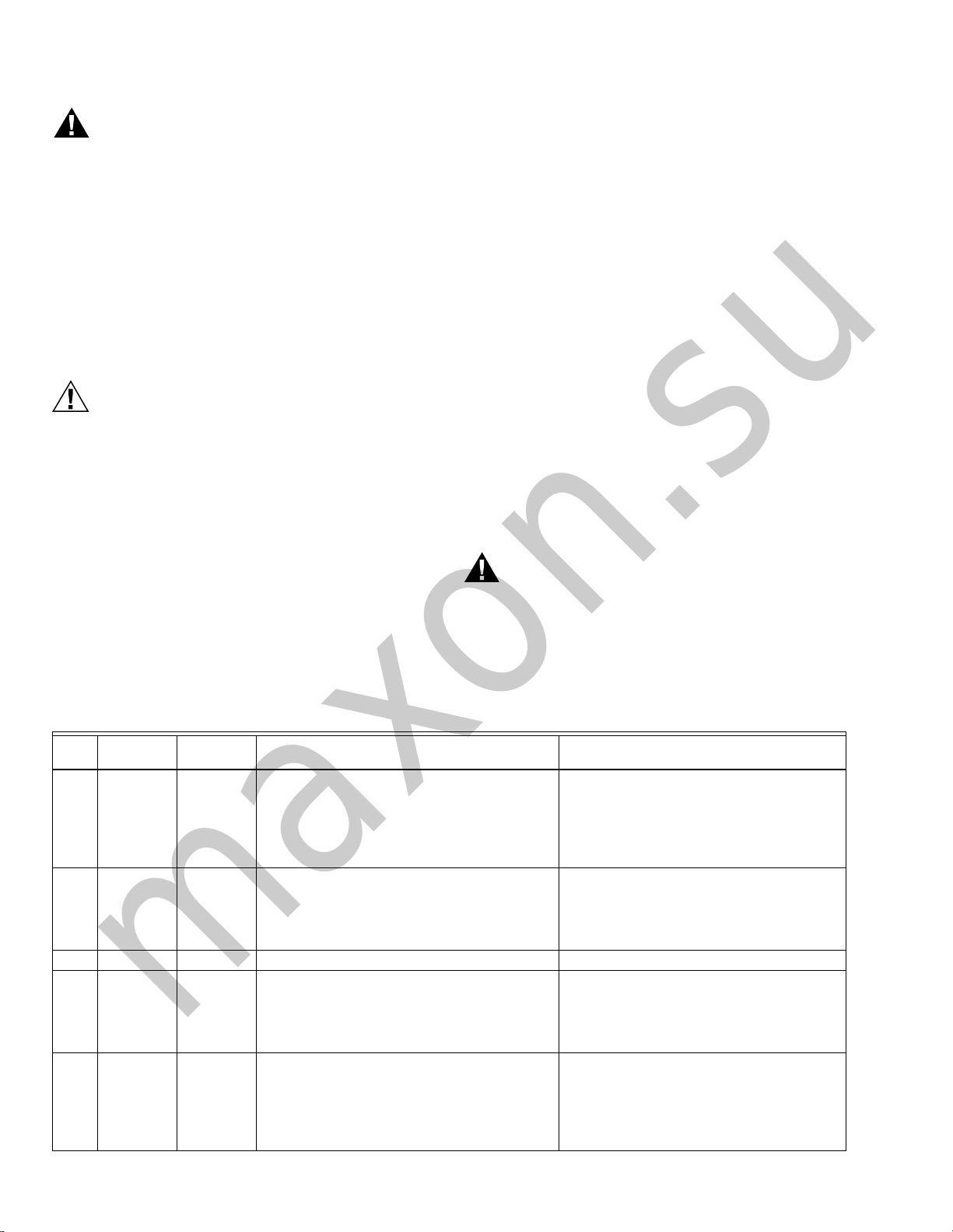
Table 3. Static Checkout.
Test
No.
1 None 4-L2 Line voltage at terminal 4. 1. Master Switch.
2 None 6-L2 Close burner control.
2a None 4-20 Line voltage at terminal 20. Preignition Interlock.
2b None
2c None
Test
Jumpers Voltmeter Normal Operation
Recirculating exhaust blower fan starts, then
line voltage at terminal 6.
4-16 Line voltage at terminal 16. Pilot Valve Hold.
Close
Pilot
Val ve
Hold
4-17 Line voltage at terminal 17. Manual Open Valve Switch.
Close
Manual
Open
Val ve
Switch
Explosion Hazard.
Can cause serious injury or death.
Make sure all manual fuel shutoff valves are closed.
If Operation is Abnormal, Check These
2. Power Connected to the Master
Switch.
3. Overload protection (fuse, circuit
breaker, etc) has not opened the power
line.
1. Recirculating/exhaust blower fan.
2. Limits.
3. Stop Switch.
4. Burner Control.
5. Recirculating AFS.
NOTE: C1020 does not have Pilot Valve
Hold.
NOTE: C1020 does not have MOV.
Items
66-1094—08 6
 Loading...