

Page 1

SIL
3
Capable
RM7838B,C
maxon.su
7800 SERIES Relay Module
INSTALLATION INSTRUCTIONS
APPLICATION
The Honeywell RM7838B,C is a microprocessor based
integrated burner control for industrial process modulating
semiautomatically fired gas, oil, coal or combination fuel
single burner applications. The RM7838B,C System consists
of a relay module, wiring subbase, keyboard display module
(KDM), amplifier, and purge card. Options include Data
ControlBus Module™, remote display mounting, and first-out
expanded annunciator.
Functions provided by the RM7838B,C include automatic
modulated High Fire and Low Fire proven Purge, burner pilot
startup with pilot valve hold, a special pilot valve hold from the
Run condition, flame supervision, system status indication,
system or self-diagnostics and troubleshooting.
The RM7838C differs from the RM7838B as follows:
1. Alarms only on Safety Shutdown.
2. Requires ST7800C Purge Timer.
3. C1004 has 15 second MFEP. C1020 has 5 second
MFEP.
This document provides installation and static checkout
instructions. Other applicable publications are:
65-0084: Q7800A,B 22-Terminal Wiring Subbase
Product Data.
65-0089: ST7800A,C Plug-In Purge Timer
Installation Instructions.
65-0090: S7800A Keyboard Display Module
Product Data.
65-0101: S7830 Expanded Annunciator Product
Data.
65-0109: R7824, R7847, R7848, R7849, R7851,
R7852, R7861, R7886 Flame Amplifiers
for the 7800 Series Product Data.
65-0131: 221818A Extension Cable Assembly
Product Data.
65-0229: 7800 Series Relay Modules Checkout and
Troubleshooting Product Data.
65-0249: S7810M ModBus™ Module Product Data.
SPECIFICATIONS
Electrical Ratings (See Table 4):
Voltage and Frequency: 120 Vac (+10/-15%),
50/60 Hz (±10%).
Power Dissipation:
RM7838B,C: 10W maximum.
Maximum Total Connected Load: 2000 VA.
Fusing Total Connected Load: 15A maximum, type SC or
equivalent, fast blow.
Environmental Ratings:
Ambient Temperature:
Operating: -40°F to +140°F (-40°C to +60°C).
Storage: -40°F to +150°F (-40°C to +66°C).
Humidity: 85% relative humidity continuous, noncondensing.
Vibration: 0.5G environment.
SIL 3 Capable:
SIL 3 Capable in a properly designed Safety Instrumented
System. See form number 65-0312 for Certificate Agree-
ment.
Approvals:
Underwriters Laboratories Inc. Listed: File No. MP268, Guide
No. MCCZ.
Canadian Standards Association Certified: LR9S329-3.
Factory Mutual Approved: Report No. 1V9A0.AF.
Swiss Re (formerly Industrial Risk Insurers): Acceptable.
Federal Communications Commission: Part 15, Class B,
Emissions.
Gastec: EN298, Report 115679/4 (RM7838C1020 only)
IMPORTANT
A Flame Detection System is required for operation
and must be ordered separately. Select the
applicable Flame Signal Amplifier and matching
Flame Detector in form 65-0109.
INSTALLATION
When Installing this Product...
1. Read these instructions carefully. Failure to follow
them could damage the product or cause a hazardous
condition.
2. Check the ratings given in the instructions and marked
on the product to make sure the product is suitable for
the application.
3. Installer must be a trained, experienced, flame
safeguard service technician.
4. After installation is complete, check out the product
operation as provided in these instructions.
RM7838C1020 only
66-1094-08
Page 2

RM7838B,C 7800 SERIES RELAY MODULE
WARNING
WARNING
WARNING
maxon.su
Explosion or Fire Hazard.
Can cause severe personal injury, death or
property damage.
To prevent possible hazardous burner operation, verify
safety requirements each time a control is installed on
a burner.
Electrical Shock Hazard.
Can cause electrical shock or equipment damage.
Disconnect the power supply before beginning
installation. More than one power supply disconnect
can be required.
Location
Humidity
Install the relay module where the relative humidity never
reaches the saturation point. The relay module is designed to
operate in a maximum 85% relative humidity continuous,
noncondensing, moisture environment. Condensing moisture
can cause a safety shutdown.
Vibration
Do not install the relay module where it can be subjected to
vibration in excess of 0.5G continuous maximum vibration.
Weather
The relay module is not designed to be weather tight. When
installed outdoors, protect the relay module in an approved
weather-tight enclosure.
Mounting Wiring Subbase
1. Mount the subbase in any position except horizontally
with the bifurcated contacts pointing down. The
standard vertical position is recommended; any other
position decreases the maximum ambient temperature
rating.
2. Select a location on a wall, burner or electrical panel.
The Q7800 can be mounted directly in the control
cabinet; be sure to allow adequate clearance for
service, installation, access or removal of the
RM7838B,C, Expanded Annunciator, KDM, flame
amplifier, flame amplifier signal voltage probes,
Run/Test Switch, electrical signal voltage probes and
electrical field connections.
3. For surface mounting, use the back of the subbase as a
template to mark the four screw locations; then drill the
pilot holes.
4. Securely mount the subbase using four no. 6 screws.
IMPORTANT
1. Wiring connections for the relay modules are unique;
refer to Fig. 2 and 3 or the appropriate Specifications
for proper subbase wiring.
2. Wiring must comply with all applicable codes,
ordinances and regulations.
3. Wiring must comply with NEC Class 1
(Line Voltage) wiring.
4. Loads connected to the RM7838B,C must not
exceed those listed on the RM7838B,C label or the
Specifications; see Table 4.
5. Limits and interlocks must be rated to simultaneously
carry and break current to the ignition transformer,
pilot valve, and main fuel valve(s).
6. All external timers must be listed or component
recognized by authorities who have proper
jurisdiction.
7. For on-off gas-fired systems, some authorities who
have jurisdiction prohibit the wiring of any limit or
operating contacts in series between the flame
safeguard control and the main fuel valve(s).
8. Two Flame Detectors can be connected in parallel
with the exception of Infrared Flame Detectors
(C7015 and C7915), UV Flame Detectors C7927,
and C7961 and visible light detector C7962.
9. This equipment generates, uses and can radiate
radio frequency energy and, if not installed and used
in accordance with the instructions, can cause
interference with radio communications. It has been
tested and found to comply with the limits for a
Class B computing device of Part 15 of FCC rules,
which are designed to provide reasonable protection
against such interference when operated in a
commercial environment. Operation of this
equipment in a residential area can cause
interference; in which case, the users, at their own
expense, may be required to take whatever
measures are required to correct this interference.
10. This digital apparatus does not exceed the Class B
limits for radio noise for digital apparatus set out in
the Radio Interference Regulations of the Canadian
Department of Communications.
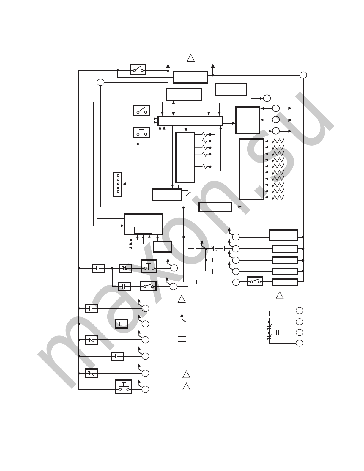
See Fig. 1 for the internal block diagram of the RM7838B,C
Relay Module.
Wiring Subbase
Electrical Shock Hazard.
Can cause serious personal injury, death or
equipment damage.
Disconnect the power supply before beginning
installation. More than one power supply disconnect
may be required.
1. Refer to Fig. 2 or 3 for proper subbase wiring.
2. For proper remote wiring of the KDM, refer to the KDM
Specifications (65-0090), Data ControlBus Module™
(65-0091) or Extension Cable Assembly (65-0131).
3. Make sure all wiring complies with all applicable
electrical codes, ordinances and regulations. Wiring,
where required, must comply with NEC, Class 1
(Line Voltage) wiring.
66-1094—08 2
Page 3
4. See Table 1 for recommended wire size and type.
maxon.su
RM7838B,C 7800 SERIES RELAY MODULE
4
DDL
COMMUNICATIONS
RECIRCULATING
AFS
LOCKOUT INTERLOCKS
AND COMBUSTION AIR
BLOWER SWITCHES
PILOT VALVE
HOLD SWITCH
LOW START
SWITCH
HIGH PURGE
RATE SWITCH
PREIGNITION
INTERLOCK
BURNER CONTROL
RUN/TEST
SWITCH
RESET
PUSHBUTTON
STATUS LED
KEYBOARD
DDL
MANUAL VALVE
OPEN SWITCH
DISPLAY MODULE
LIMITS
START SWITCH
RS485
1
2
3
STOP SWITCH
1/2 OF DPST
ALARM SILENCING
SWITCH
16
17
18
19
20
21
L1
(HOT) L2
CONFIGURATION
JUMPERS
SAFETY RELAY
CIRCUIT
REMOTE
RESET
1
120 Vac
50/60 HZ
RECIRCULATING
BLOWER
MICROCOMPUTER
RELAY
DRIVE
CIRCUIT
6
7
2
INDICATES FEEDBACK SENSING
OF RELAY CONTACT STATUS
AND LINE VOLT INPUTS
FIELD WIRING
INTERNAL WIRING
PROVIDE DISCONNECT MEANS AND
1
OVERLOAD PROTECTION AS REQUIRED.
2
NOT REQUIRED FOR RM7838C.
PLUG-IN PURGE
TIMER CARD
FLAME SIGNAL
2K
3K
4K
5K
7K
1K
POWER SUPPLY
6K1
1K1 2K1 5K1
4K1
2K2
3K1
TEST
PLUG-IN
FLAME
AMPLIFIER
RELAY
STATUS
FEEDBACK
AND LINE
VOLTAGE
INPUTS
CONTROL
POWER
5
10
8
9
3
1/2 OF DPST
ALARM SILENCING
SWITCH
8K1
8K2
9K2
TEST
JACK
F
G
22
COMBUSTION
AIR BLOWER
IGNITION
PILOT
MAIN VALVE
ALARM
2
HIGH PURGE
COMMON
MODULATE
9K1
LOW FIRE
M5195D
L2
12
13
15
14
Fig. 1. Internal block diagram of RM7838B,C (see Fig. 2 for RM7838C1020); see Fig. 3 and 4 for detailed wiring
instructions.
3 66-1094—08
Page 4
RM7838B,C 7800 SERIES RELAY MODULE
L1
HOT
N
1
4
2
19
CONFIGURATION
JUMPERS
PLUG-IN PURGE
TIMER CARD
F
G
22
PLUG -IN
FLAM E
A M P L IF IE R
PLUG-IN
FLAME
AMPLIFIER
MICROCOMPUTER
RUN/TEST
SWITCH
RESET
PUSHBUTTON
FLAM E SIGNAL
TEST
JACK
RELAY
DRIVE
CIRCUIT
1K
2K
3K
4K
5K
6K
7K
8K
9K
CONTROL
POWER
POWER SUPPLY
18
20
RELAY
STATUS
FEEDBACK
AND LINE
VOLTAGE
INPUTS
10
8
9
5
3
OPTIONAL KEYBOARD
DISPLAY MODULE
RS485
16
1K
2K2 5K1
4K1
2K1
PV1
MV
3K1
6K1
21
LFS
HFS
PII
3K2
SAFETY RELAY
CIRCUIT
7
COMBUSTION
BLOWER
AL
IGN
AL
DDL
13
15
14
12
HIGH FIRE
COMMON
LOW FIRE
MODULATE
REMOTE
RESET
8K1
8K2
9K2
9K1
INDICATES FEEDBACK SENSING
OF RELAY CONTACT STATUS
AND LINE VOLTAGE INPUTS
RELAY CONTACT OPEN
INTERNAL WIRING
FIELD WIRING
RELAY COIL
RELAY CONTACT CLOSED
DDL
COMMUNICATIONS
1
2
3
5
USER TERMINALS
1
120 VAC, 50/60 Hz POWER SUPPLY.
M13959
STATUS
LEDS
SHUTTER
FG
...
22
COMBUSTION
BLOWER AFS
START
6
RECIRCULATING
BLOWER AFS
RECIRCULATING
BLOWER
L2
STOP
BURNER
CONTROL
maxon.su
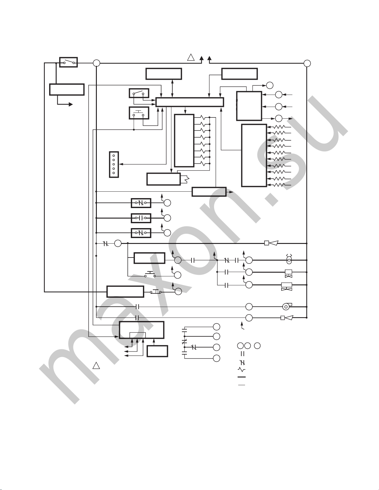
Fig. 2. Internal block diagram of RM7838C1020 (see Fig. 5 for detailed wiring instructions).
66-1094—08 4
Page 5
RM7838B,C 7800 SERIES RELAY MODULE
maxon.su
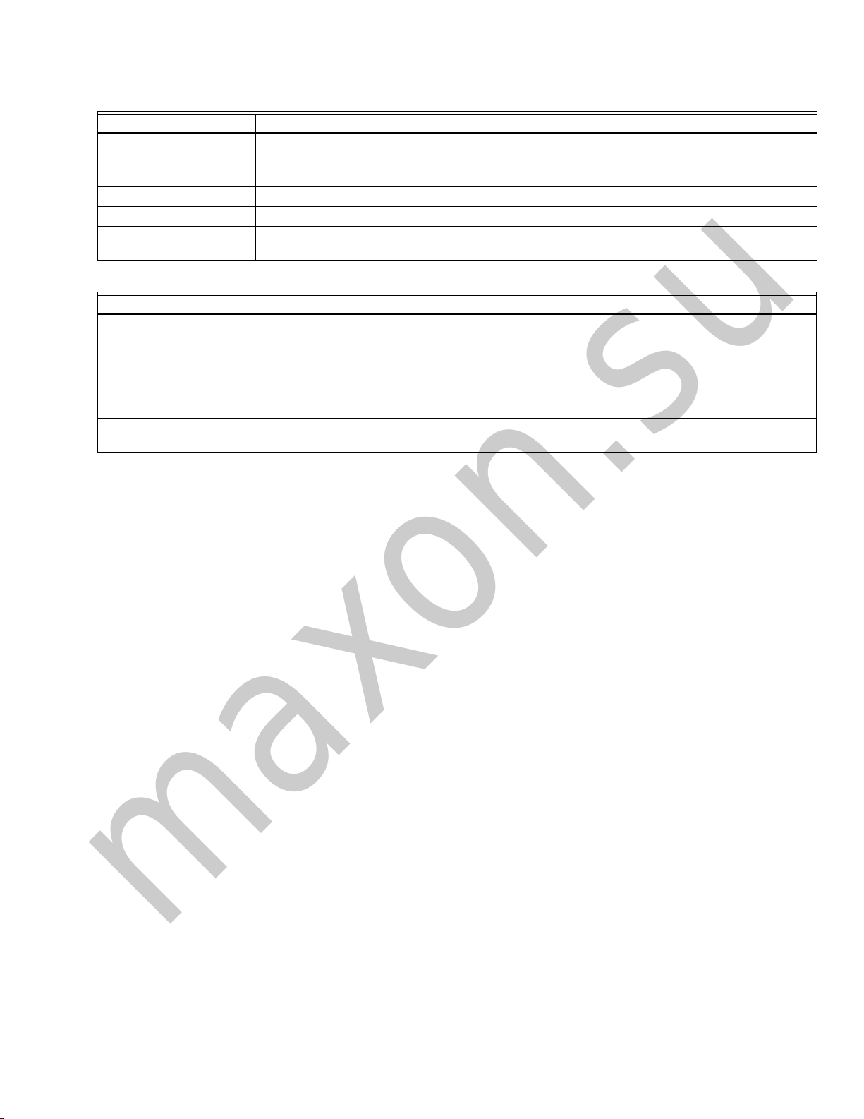
Table 1. Recommended Wire Sizes and Part Numbers.
Application Recommended Wire Size Recommended Part Numbers
Line voltage terminals 14, 16 or 18 AWG copper conductor, 600 volt
KDM 22 AWG two-wire twisted pair with ground, or five-wire. Belden 8723 shielded cable or equivalent.
Data ControlBus Module™ 22 AWG two-wire twisted pair with ground, or five-wire. Belden 8723 shielded cable or equivalent.
Remote Reset Module 22 AWG two-wire twisted pair, insulated for low voltage. —
13 Vdc full wave rectified
transformer power input.
Ground Type Recommended Practice
Earth Ground (Subbase and relay
module)
Signal Ground (KDM, Data ControlBus
Module™
insulation, moisture-resistant wire.
18 AWG wire insulated for voltages and temperatures
for given application.
Table 2. Recommended Grounding Practices.
1. Use to provide a connection between the subbase and the control panel of the
equipment. Earth ground must be capable of conducting enough current to blow
the 15A fuse (or breaker) in the event of an internal short circuit.
2. Use wide straps or brackets to provide minimum length, maximum surface area
ground conductors. If a lead wire must be used, use 14 AWG copper wire.
3. Make sure that mechanically-tightened joints along the ground path are free of
nonconductive coatings and protected against corrosion on mating surfaces.
Use the shield of the signal wire to ground the device to the signal ground terminal 3(c)
of each device. Connect the shield at both ends of the daisy chain to earth ground.
TTW60C, THW75C, THHN90C.
TTW60C, THW75C, THHN90C.
The KDM and Data ControlBus™ Module (for remote
mounting or communications) must be wired in a daisy chain
configuration, 1(a)-1(a), 2(b)-2(b), 3(c)-3(c). The order of
interconnection of all the devices listed above is not important.
Be aware that modules on the closest and farthest end of the
daisy chain configuration string require a 120 ohm (1/4 watt
minimum) resistor termination across terminals 1 and 2 of the
electrical connectors, for connections over 100 feet (31
meters).
4. See Table 2 for recommended grounding practices.
5. Use recommended wire routing of leadwires:
a. Do not run high voltage ignition transformer wires in
the same conduit with the flame detector, Data
ControlBus Module™, or Remote Reset Module
wiring.
b. Do not route flame detector, Data ControlBus
Module™, or Remote Reset Module leadwires in
conduit with line voltage circuits.
c. Enclose flame detector leadwires without armor
cable in metal cable or conduit.
d. Follow directions in flame detector, Data ControlBus
Module™, or Remote Reset Module Instructions.
6. KDM: Because the KDM is powered from a low voltage,
energy limited source, mount it outside of a control
panel if it can be protected from mechanical damage.
NOTE: Use a separate 13 Vdc power supply any time more
than two Data ControlBus Modules™ or KDM are
used or are placed more than 100 feet (31 meters)
from the relay module.
7. Use maximum wire lengths:
a. RM7838B,C leadwires—300 feet (91 meters) to
terminal inputs (Control, Preignition Interlock,
Running/Lockout Interlock, High Purge Switch and
Low Fire Switch).
b. Flame Detector leadwires—limited by the flame
signal strength.
c. Remote Reset leadwires—1000 feet (305 meters) to
a Remote Reset push button.
d. Data ControlBus™ Module—depends on the
number of system modules connected, the noise
conditions and the cable used. The maximum length
of all Data ControlBus™ Module interconnecting
wire is 4000 feet (1219 meters).
8. Make sure loads do not exceed the terminal ratings.
Refer to the label on the RM7838B,C or to the ratings in
Table 4.
FINAL WIRING CHECK
1. Check the power supply circuit. The voltage and fre-
quency tolerance must match those of the RM7838B,C.
(A separate power supply may be required for the
RM7838B,C.)
2. Add the required disconnect means and overload
protection.
3. Check all wiring circuits and complete the static
checkout in Table 3 before installing the RM7838B,C on
the subbase.
4. Install the relay module.
5. Restore power to the panel.
STATIC CHECKOUT
After checking all wiring, perform this checkout before
installing the RM7838B,C on the subbase. These tests verify
the Q7800 Wiring Subbase is wired correctly, and the external
controllers, limits, interlocks, actuators, valves, transformers,
motors and other devices are operating properly.
5 66-1094—08
Page 6
RM7838B,C 7800 SERIES RELAY MODULE
WARNING
CAUTION
WARNING
maxon.su
Explosion and Electrical Shock Hazards.
Can cause serious injury, death or equipment
damage.
Close all manual fuel shutoff valve(s) before starting
these tests.
Use extreme care while testing the system. Line
voltage is present on most terminal connections when
power is on.
Open the master switch before installing or removing a jumper
on the subbase. Before continuing to the next test, be sure to
remove test jumper(s) used in the previous test. Replace all
limits and interlocks that are not operating properly. Do not
bypass limits and interlocks.
Electrical Hazard.
Can cause equipment damage.
Do not perform a dielectric test with the RM7838B,C
installed. Internal surge protectors break down and
conduct current, causing dielectric test failure and
destruction of the internal lightning and high current
protection.
General Instructions
1. Perform all applicable tests listed in the Static Checkout,
Table 3, in the order listed.
2. Make sure all manual fuel shutoff valve(s) are closed.
3. Perform only those tests designated for the specific
RM7838B,C model being tested.
4. Raise the setpoint of the operating controller to simulate
a call for heat.
5. For each test, open the master switch and install the
jumper wires between the subbase wiring terminals
listed in the Test Jumpers column.
6. Close the master switch before observing operation.
7. Read the voltage between the subbase wiring terminals
listed in the Voltmeter column.
8. If there is no voltage or the operation is abnormal, check
the circuits and external devices as described in the last
column.
9. Check all wiring for correct connections, tight terminal
screws, correct wire, and proper wiring techniques.
Replace all damaged or incorrectly sized wires.
10. Replace faulty controllers, limits, interlocks, actuators,
valves, transformers, motors and other devices, as
required.
11. Make sure normal operation is obtained for each
required test before continuing the checkout.
12. After completing each test, be sure to remove the test
jumper(s).
Equipment Recommended
Voltmeter (1M ohm/volt minimum sensitivity) set on the
0-300 Vac scale and two jumper wires; using No. 14 wire,
insulated, 12 in. (304.8 mm) long with insulated alligator clips
at both ends. An ammeter to test the load current can replace
one of the recommended jumpers in tests verifying the
combustion blower motor, ignition, pilot and main valve
operation.
Table 3. Static Checkout.
Test
No.
1 None 4-L2 Line voltage at terminal 4. 1. Master Switch.
2 None 6-L2 Close burner control.
2a None 4-20 Line voltage at terminal 20. Preignition Interlock.
2b None
2c None
Test
Jumpers Voltmeter Normal Operation
Recirculating exhaust blower fan starts, then
line voltage at terminal 6.
4-16 Line voltage at terminal 16. Pilot Valve Hold.
Close
Pilot
Val ve
Hold
4-17 Line voltage at terminal 17. Manual Open Valve Switch.
Close
Manual
Open
Val ve
Switch
Explosion Hazard.
Can cause serious injury or death.
Make sure all manual fuel shutoff valves are closed.
If Operation is Abnormal, Check These
2. Power Connected to the Master
Switch.
3. Overload protection (fuse, circuit
breaker, etc) has not opened the power
line.
1. Recirculating/exhaust blower fan.
2. Limits.
3. Stop Switch.
4. Burner Control.
5. Recirculating AFS.
NOTE: C1020 does not have Pilot Valve
Hold.
NOTE: C1020 does not have MOV.
Items
66-1094—08 6
Page 7

RM7838B,C 7800 SERIES RELAY MODULE
CAUTION
maxon.su
Table 3. Static Checkout. (Continued)
Test
No.
3 None 21-L2 With test 2 still running, press Start Switch. 120
4 None 6-L2 Push and hold Stop Switch. No voltage present
5 4-3 None Alarm (if used) turns on. 1. Alarm.
6 4-5 7-L2 Close burner control. Recirculating/exhaust
7 4-8 None Automatic pilot valve opens. First stage valve
8 4-9 None Automatic main fuel valves open. (DSI checks
9 4-10 None Ignition spark (if ignition transformer connected
10 12-13 18-L2 Firing rate motor drives open; zero volts at
11 12-13 19-L2 Firing rate motor reaches High Purge Rate
12 13-14
13 13-14
14 13-15
Final
Test
Jumpers Voltmeter Normal Operation
Vac is present at terminal 21.
at terminal 6.
blower fan starts, then line voltage is present at
terminal 6.
1. Combustion air fan starts.
2. Line voltage at terminal 7 within 10 seconds.
(DSI application only).
Ignition spark (if ignition transformer
connected).
optional second state fuel valve.)
to terminal 10.
terminal 18 after motor leaves Low Fire position.
position; 120 Vac at terminal 19 when High
Purge Rate Switch closes.
19-L2 Firing rate motor leaves High Purge Rate
(13-15 for
C1020)
18-L2 Firing rate motor drives to Low Purge Rate
(13-15 for
C1020)
None Adjust firing rate control and watch tracking
(13-14 for
C1020)
Position; zero Vac at terminal 19 when High
Purge Rate Switch opens.
position; 120 Vac at terminal 18 when switch
closes.
action of the firing rate motor.
If Operation is Abnormal, Check These
1. Start Switch.
2. Preignition Interlock.
Stop Switch.
2. Alarm Silencing Switch (B model only).
1. Combustion air fan circuit:
a. Manual switch on air fan motor.
b. Air fan power supply, overload protec-
tion, and starter.
2. Combustion Blower Air Flow Switch.
3. Alarm Silencing Switch (B model only).
4. Recirculating Air Flow Switch.
1. Listen for click or feel head of valve for
activation.
2. Watch for spark or listen for buzz:
a. Ignition electrodes are clean.
b. Ignition transformer is okay.
Listen for and observe operation of the main
fuel valve(s) and actuator(s).
1. Watch for spark or listen for buzz:
a. Ignition electrodes are clean.
b. Ignition transformer is okay.
1. Low Fire Start Switch.
2. Firing rate motor and transformer.
1. High Purge Rate Switch.
2. Firing rate motor and transformer.
1. High Purge Rate Switch.
2. Firing rate motor and transformer.
1. Low Purge Rate Switch.
2. Firing rate motor and transformer.
1. Firing rate control.
2. Firing rate motor and transformer.
Items
Electrical Hazard.
Can cause equipment damage.
After completing these tests, open the Master Switch and remove all test jumpers from the subbase terminals.
Also remove bypass jumpers from the low fuel pressure limits if used.
7 66-1094—08
Page 8

RM7838B,C 7800 SERIES RELAY MODULE
maxon.su
Table 4. Terminal Ratings.
Terminal No. Description Ratings
G
Earth G
L2 Line Voltage Common —
3 Alarm 120 Vac, 1A pilot duty.
4 Line Voltage Supply (L1)
5 Combustion Blower 120 Vac, 9.8 AFL, 58.8 ALR (inrush).
6 Stop Input 120 Vac, 1 mA.
7 Lockout Interlock 120 Vac, 8A running, 43A inrush.
8 Interrupted Pilot
9 Main Fuel Valve
10 Ignition
F(11) Flame Sensor 60 to 220 Vac, current limited.
12 Firing Rate High Fire 120 Vac, 75 VA pilot duty.
13 Firing Rate Common 120 Vac, 75 VA pilot duty.
14 Firing Rate Low Fire 120 Vac, 75 VA pilot duty.
15 Firing Rate Modulate 120 Vac, 75 VA pilot duty.
16 Pilot Valve Hold Input 120 Vac, 1 mA.
17 Manual Open Switch 120 Vac, 1 mA.
18 Low Fire Switch 120 Vac, 1 mA.
19 High Fire Switch 120 Vac, 1 mA.
20 Preignition Interlock 120 Vac, 1 mA.
21 Start Switch Input 120 Vac, 1A pilot duty.
22 Shutter 120 Vac, 0.5A.
a
See Table 2.
b
2000 VA maximum load connected to RM7838B,C Assembly.
c
See Tables 5 and 6.
Flame Sensor Ground
Earth Ground
a
a
—
—
120 Vac (+10/-15%), 50/60 Hz (+/-10%).
120 Vac.
120 Vac.
120 Vac.
c
c
c
b
Table 5. Combinations for Terminals 8, 9, and 10.
Pilot Fuel 8 Main 9 Ignition 10
C F No Load
B F No Load
FF A
No Load
DF A
DD A
No Load
a
Jumper Terminals 8 to 9 for direct spark ignition.
ABCDF
4.5A ignition 50 VA Pilot Duty plus
4.5A ignition
66-1094—08 8
a
F
a
D
Table 6. Composition of Each Combination.
180 VA Ignition plus
Motor Valves with:
660 VA inrush,
360 VA open,
250 VA hold.
2A Pilot Duty 65 VA Pilot Duty plus
A
A
motor valves with:
3850 VA inrush,
700 VA open,
250 VA hold.
Page 9

RM7838B,C 7800 SERIES RELAY MODULE
maxon.su
Table 7. RM7838C1020 Alternate Terminal Ratings
Terminal No. Abbreviation Description Ratings
G—
Earth G —
N — Line Voltage Common (Neutral) —
3 AL Alarm (Normally Open) 1A, 10A inrush for 5000 cycles
4 L1 Line Voltage Supply (L1)
5 FAN Combustion Blower Motor
6 — Stop Input 1mA
7 LD2 Airflow Switch Input (Lockout Interlock) 5A
8 pv1 Pilot Valve 1 (Interrupted)
9 MV Main Fuel Valve
10 IGN Ignition 2A at PF = 0.2
F(11) — Flame Sensor 60 to 220 Vac, current limited.
12 HI Firing Rate High Fire
13 COM Firing Rate Common
14 MOD Firing Rate Modulate
15 LO Firing Rate Low FIre
16 — Alarm (Normally Closed) 1A, 10A inrush for 5000 cycles; carry 5A for
17 —
18 ES1 Low Fire Switch Input 1mA
19 ES3 High Fire Switch Input 1mA
20 LOS Preignition Interlock 1mA
21 Start Switch Start Switch 1mA
22 SHTR Shutter Shutter drive for dynamic self-check flame
a
See Table 2.
b
2000 VA maximum connected load to relay module.
c
Honeywell has tested this output at 9.8A at PF = 0.5, 58.A inrush for 100,000 cycles
d
Total load current, excluding Burner/Boiler Motor and Firing Rate Outputs cannot exceed 5A, 25A inrush.
e
Can also be 24Vac, 3A at PF = 0.5.
Flame Sensor Ground
Earth Ground
a
a
—
—
120 Vac (+10/-15%), 50/60 Hz (+/-10%).
4A at PF =0.5, 20A inrush
4A at PF = 0.5, 20A inrush
4A at PF = 0.5, 20A inrush
0.5A at PF = 0.5
0.5A at PF = 0.5
0.5A at PF = 0.5
0.5A at PF = 0.5
250,000 cycles
sensor.
e
e
e
e
c
d
d
b
9 66-1094—08
Page 10

RM7838B,C 7800 SERIES RELAY MODULE
maxon.su
L2
L1
(HOT)
1
MASTER
SWITCH
RECIRCULATING
BLOWER
Q7800 SUBBASE
G
12
HIGH FIRE
SERIES 90
FIRING RATE
MOTOR
B
SERIES 90
CONTROLLER
B
BURNER
CONTROL
DPST ALARM
SILENCING SWITCH
120V ALARM
RECIRCULATING
AFS
1
120V, 50/60 HZ POWER SUPPLY. PROVIDE DISCONNECT MEANS AND OVERLOAD PROTECTION AS REQUIRED.
2
SHUTTER CHECK FLAME DETECTION SYSTEM REQUIRED WHEN USING THE PILOT VALVE HOLD FUNCTION.
SEE FLAME DETECTOR INSTALLATION INSTRUCTIONS FOR CORRECT WIRING.
3
15 SECOND FOR RM7838C.
4
ALARM SILENCING SWITCH NOT NEEDED FOR RM7838C APPLICATIONS.
5
COMBUSTION
BLOWER AFS
S445
STOP
A
B
START
D
C
3
COMBUSTION
AIR FAN
INTERMITTENT/
10 SECOND
INTERRUPTED
PILOT/IGNITION
MAIN FUELVALVE(S)
5 SECOND IGNITION
(EARLY SPARK
TERMINATION)
FLAME DETECTOR
5
LIMITS
4
L2
3
4
(L1)
5
6
7
8
9
10
F
13
14
15
16
17
18
19
20
21
22
COMMON
LOW FIRE
MODULATE
PILOT VALVE
HOLD
MANUAL VALVE
OPEN SWITCH
LOW FIRE
START SWITCH
HIGH PURGE
RATE SWITCH
PREIGNITION
INTERLOCK
R
W
R
W
2
M15101D
Fig. 3. Wiring subbase for RM7838B,C with S445 Start-Stop Station (not the RM7838C1020).
66-1094—08 10
Page 11

L2
maxon.su
L1
(HOT)
1
BURNER
CONTROL
RECIRCULATING
AFS
MASTER
SWITCH
START
RECIRCULATING
BLOWER
120V ALARM
COMBUSTION
BLOWER AFS
STOP
DPST ALARM
SILENCING SWITCH
5
COMBUSTION
BLOWER
LIMITS
INTERMITTENT/
10 SECOND
INTERRUPTED
PILOT/IGNITION
MAIN FUEL
VALVE(S)
5 SECOND IGNITION
(EARLY SPARK
TERMINATION)
FLAME DETECTOR
4
Q7800 SUBBASE
G
L2
3
4
5
6
7
8
9
10
F
(L1)
12
13
14
15
16
17
18
19
20
21
22
RM7838B,C 7800 SERIES RELAY MODULE
SERIES 90
FIRING RATE
MOTOR
HIGH FIRE
COMMON
LOW FIRE
MODULATE
PILOT VALVE
HOLD
MANUAL VALVE
OPEN SWITCH
LOW FIRE
START SWITCH
HIGH PURGE
RATE SWITCH
PREIGNITION
INTERLOCK
SERIES 90
CONTROLLER
B
R
W
2
B
R
W
HIGH FIRE
COMMON
LOW FIRE
MODULATE
3
M7284 4-20 mA
FIRING RATE
MOTOR
F
–
++
OUTPUT
CONTROLLER
–
120V, 50/60 HZ POWER SUPPLY. PROVIDE DISCONNECT MEANS AND OVERLOAD PROTECTION AS REQUIRED.
1
2
SHUTTER CHECK FLAME DETECTION SYSTEM REQUIRED WHEN USING THE PILOT VALVE HOLD FUNCTION.
ALTERNATIVE WIRING FOR 4-20 MA SYSTEM.
3
SEE FLAME DETECTOR INSTALLATION INSTRUCTIONS FOR CORRECT WIRING.
4
ALARM SILENCING SWITCH NOT NEEDED FOR RM7838C APPLICATIONS.
5
Fig. 4. Wiring subbase for RM7838B,C with separate Start and Stop Stations (not the RM7838C1020).
M15100C
11 66-1094—08
Page 12

RM7838B,C 7800 SERIES RELAY MODULE
G
12
L2
13
314
415
5
16
6
17
718
819
920
10
21
F
22
ALARM
COMBUSTION BLOWER
RECIRCULATING
BLOWER AFS
COMBUSTION BLOWER AFS
INTERMITTENT/10 SECOND
INTERRUPTED PILOT/
IGNITION
5 SECOND IGNITION
MAIN FUEL VALVE(S)
F
–
+
–
+
HIGH FIRE
COMMON
MODULATE
LOW FIRE
LOW FIRE START SWITCH
HIGH PURGE RATE SWITCH
PREIGNITION INTERLOCK
FLAME DETECTOR
1
120 VAC, 50/60 HZ POWER SUPPLY. PROVIDE DISCONNECT MEANS AND OVERLOAD PROTECTION AS REQUIRED.
SEE FLAME DETECTOR INSTRUCTIONS FOR CORRECT WIRING.
Q7800
2
START
2
STOP
L1
L2
1
RECIRCULATING
BLOWER
M29090
BURNER
CONTROL
maxon.su
Fig. 5. Hookup of RM7838C1020.
Mounting RM7838B,C Relay Module
1. Mount the RM7838B,C vertically on the Q7800
Subbase, or mount horizontally with the knife blade
terminals pointing down. (For mounting on the Q7800A,
2. When mounting in an electrical enclosure, provide
mount the RM7838B,C in an electrical enclosure.)
adequate clearance for service, installation and removal
of the RM7838B,C, KDM, flame amplifier, flame
amplifier signal voltage probes, electrical signal voltage
probes, and electrical connections.
a. Allow an additional 2 in. (51 mm) below the
RM7838B,C for the flame amplifier mounting.
b. Allow an optional 3 in. (76 mm) minimum to both
sides of the RM7838B,C for electrical signal voltage
probes.
3. Make sure no subbase wiring is projecting beyond the
terminal blocks. Tuck in wiring against the back of the
subbase so it does not interfere with the knife blade
terminals or bifurcated contacts.
IMPORTANT
Install the RM7838B,C with a plug-in motion rather
than a hinge action.
4. Mount the RM7838B,C by aligning the four L-shaped
corner guides and knife blade terminals with the
bifurcated contacts on the wiring subbase and securely
tightening the two screws without deforming the plastic.
66-1094—08 12
Page 13

RM7838B,C 7800 SERIES RELAY MODULE
HONEYWELL
POWER
PIL
OT
FLAME
MAIN
ALARM
RES
ET
KEYBOARD
DISPLAY
MODULE
PURGE
TIMER
WIRING
SUBBASE
CAPTIVE
MOUNTING
SCREW
RUN/TEST
SWITCH
CONFIGURATION
JUMPERS
RELAY
MODULE
SEQUENCE
STATUS
LED PANEL
RESET
BUTTON
FLAME
AMPLIFIER
SCR
OLL
MODE
- SAV
E -
BURNER CONTROL
M1230
maxon.su
Mounting Other System Components (Fig. 4)
Mount other required and optional system components by
referring to Fig. 4 and the instructions provided with each
component.
PRINCIPAL TECHNICAL FEATURES
The RM7838B,C provides all customary flame safeguard
functions as well as significant advancements in safety,
annunciation and system diagnostics.
Fig. 6. RM7838B,C Relay Module exploded view.
Safety Shutdown (Lockout) Occurs If:
1. INITIATE Period
a. Purge card is not installed or removed.
b. Purge card is bad.
c. Configuration jumpers were changed after
200 hours of operation.
d. AC line power errors, see Operation.
e. Four minute INITIATE period is exceeded.
2. STANDBY Period
a. Flame signal is present after 240 seconds after Run
Complete.
b. Preignition Interlock is open after 30 seconds.
c. Ignition/pilot valve terminal is energized.
d. Main valve terminal is energized.
e. Internal system fault.
f. Purge card is not installed or removed.
g. Purge card is bad.
h. Flame detected during the last two seconds.
13 66-1094—08
Page 14

RM7838B,C 7800 SERIES RELAY MODULE
maxon.su
3. PURGE Period
a. Preignition Interlock opens anytime during purge.
b. Flame signal detected during purge .
c. High Purge Rate Switch fails to close within four
minutes, fifteen seconds after the firing rate motor is
commanded to drive to high fire position.
d. Low Fire Start Switch fails to close within four min-
utes, fifteen seconds after the firing rate motor is
commanded to drive to low fire position.
e. Lockout Interlock does not close within five sec-
onds.
f. Lockout Interlock opens during purge .
g. Ignition/pilot valve/intermittent pilot valve terminal is
energized.
h. Main valve terminal is energized.
i. Internal system fault.
j. Purge card is not installed or removed.
k. Purge card is bad.
4. Purge Hold: T21
a. Preignition Interlock opens.
b. Flame is detected.
c. Lockout Interlock opens during Hold.
d. Ignition/pilot valve/main valve is energized.
e. Internal system fault.
f. Purge card is removed.
g. Purge card is bad.
5. PILOT FLAME ESTABLISHING Period (PFEP)
a. Low Fire Switch opens.
b. Lockout Interlock opens .
c. Ignition/pilot valve/intermittent pilot valve terminal is
not energized.
d. No flame is present at end of PFEP.
e. Internal system fault.
f. Purge card is not installed or removed.
g. Purge card is bad.
6. MAIN FLAME ESTABLISHING Period (MFEP)
a. Low Fire Switch opens.
b. Lockout Interlock opens .
c. Ignition/pilot valve/intermittent pilot valve terminal is
not energized.
d. Main valve terminal is not energized.
e. No flame is present at end of MFEP.
f. Internal system fault.
g. Purge card is not installed or removed.
h. Purge card is bad.
7. RUN Period
a. Flame is present.
b. Lockout Interlock opens.
c. Main valve terminal is de-energized.
d. Internal system fault.
e. Purge card is not installed or removed.
f. Purge card is bad.
8. Pilot Valve Hold
a. Low Fire Switch opens.
b. Lockout Interlock opens.
c. Ignition/pilot valve terminal is not energized.
d. No flame is present at end of PFEP.
e. Internal system fault.
f. Purge card is not installed or removed.
g. Purge card is bad.
h. Non Shutter Check Amplifier/Detector used.
OPERATION
Sequence of Operation
The RM7838B,C has the operating sequences listed below.
The RM7838B,C LED provide positive visual indication of the
program sequence: POWER, PILOT, FLAME, MAIN and
ALARM. Fig. 5 and 6 show the operating sequences not using
pilot valve hold and using pilot valve hold, respectively.
Initiate
The RM7838B,C enters the INITIATE sequence when the
Relay Module is initially powered. The RM7838B,C can also
enter the INITIATE sequence if the Relay Module verifies
voltage fluctuations of +10/-15 percent or frequency
fluctuations of ±10 percent during any part of the operating
sequence. The INITIATE sequence lasts for ten seconds
unless the voltage or frequency tolerances are not met. When
the tolerances are not met, a hold condition is initiated and
displayed on the KDM for at least five seconds. When the
tolerances are met, the INITIATE sequence restarts. If the
condition is not corrected and the hold condition exists for four
minutes, the RM7838B,C locks out. Causes for hold
conditions in the INITIATE sequence:
a. ac line dropout detection.
b. ac line noise that prevents a sufficient reading of the
line voltage inputs.
c. Low line voltage brownouts.
The Alarm, terminal 3, is energized during INITIATE
(RM7838B only).
Standby
The RM7838B,C remains in STANDBY until the Burner
Control Switch is closed. Two seconds before leaving
STANDBY, the shutter circuit is energized and verifies that no
flame is present. The Alarm, terminal 3, is energized until
flame is sensed (RM7838B only).
Purge
The RM7838B,C provides PURGE timing selectable from two
seconds to thirty minutes. The RM7838C requires the
ST7800C Purge Timer for correct operation. The ST7800C
Purge Timer will not fit into an RM7838B.
1. Closing the burner control switch starts the recirculating/
exhaust blower. PURGE sequence begins when power
is applied to the RM7838B,C through the recirculating/
exhaust blower airflow switch, Stop Station, and the limit
string to terminal 6. The Run/Test switch and all
microcomputer-monitored circuits must also be in the
correct operating state.
2. The RM7838B,C Relay Module commands the firing
rate motor to the high purge rate position by closing a
circuit between terminals 12 and 13. PURGE timing
begins when the High Fire Switch closes, providing
input to terminal 19. Four minutes, 15 seconds are
provided for the High Fire Switch to close. A jumpered
High Fire Switch adds 30 seconds to the PURGE
timing.
3. When the PURGE timing is complete, the RM7838B,C
commands the firing rate motor to the low fire position
by closing a circuit between terminals 13 and 14 (terminals 13 and 15 for the C1020). Four minutes, 15 seconds are provided for the motor to reach the low fire
position.
66-1094—08 14
Page 15

RM7838B,C 7800 SERIES RELAY MODULE
maxon.su
4. When the Low Fire Proving Switch is proven (input on
terminal 18), the RM7838B,C commands the Combustion Blower to turn on through terminal 5. A jumpered
Low Fire Switch adds 30 seconds to the PURGE timing.
5. The RM7838C will wait indefinitely for the Combustion
Airflow Switch , terminal 7, to close. Once closed, five
seconds are provided for it to stabilize. Safety shutdown
occurs if the Combustion Blower Airflow Switch opens
after this five-second period, during ignition trials or
RUN.
6. The RM7838B,C waits indefinitely for the Start Input to
terminal 21.
7. The Preignition Interlock must remain closed throughout
PURGE timing or a safety shutdown occurs.
8. The Alarm is powered during PURGE timing (RM7838B
only).
Ignition Trials
Ignition trials begin when the momentary Start input is
received at terminal 21 of the RM7838B,C. The RM7838B,C
locks out if the Start Switch is not released.
1. Pilot Flame Establishing Period (PFEP):
a. When the PFEP begins:
(1) The pilot valve and ignition transformer,
terminals 8 and 10, are energized.
(2) Five seconds into PFEP, Ignition terminal 10 is
de-energized.
(3) Flame must be proven by the end of the ten
second PFEP (four seconds if Configuration
Jumper JR1 is clipped); to allow the sequence to
continue. If a flame is not proven by the end of
PFEP, a safety shutdown occurs.
(4) During PFEP, the Low Fire Switch must remain
closed. If it opens, a safety shutdown occurs.
(5) The Preignition Interlock input is ignored
throughout the Ignition Trial state.
(6) The alarm output stops when flame is proven.
(RM7838B only)
(7) The RM7838B,C (except C1020):
(a)holds indefinitely, waiting for Manual Open
Valve command (terminal 17).
(b)holds indefinitely with a Pilot Valve Hold
command present on terminal 16.
(c)automatically sequences to Main Flame
Establishing Period (MFEP) if the
configuration jumper JR3 was clipped and the
Pilot Valve Hold Command is not present.
Manual Open Valve input, terminal 17, must
be closed at the end of MFEP.
b. With flame proven, the alarm, terminal 3, is
de-energized (RM7838B only).
2. Main Flame Establishing Period (MFEP) (except C1020
as it does not have a manual open valve switch input):
a. With the configuration jumper JR3 intact, the
RM7838B,C waits for Manual Open Valve Switch
input to terminal 17 through a Manual Open Valve
Switch. With the configuration jumper JR3 clipped
and the Pilot Valve Hold command on terminal 16
open, the RM7838B,C initiates immediate MFEP.
(1) Main valve terminal 9 is energized by the
RM7838B,C and the relay module is in the RUN
period.
(2) If configuration jumper JR2 is clipped, ten sec-
onds after terminal 9 is energized (15 seconds
for the C1004, 5 seconds for the C1020), the
pilot valve terminal 8 is de-energized. If flame is
lost during this MFEP, safety shutdown occurs
and the ALARM sounds.
(3) If configuration jumper JR3 is clipped, a Manual
Open Valve Switch input must be present at terminal 17 at the end of the MFEP or safety shutdown occurs and the Alarm sounds.
b. The C1020 proceeds immediately to a 5 sec MFEP.
Run
1. The RM7838B,C releases the firing rate motor to
modulation (terminals 13 and 15 are closed) (terminal
13 and 14 for C1020).
2. The RM7838B,C is now in RUN and remains in RUN
until the controller input, terminal 6, opens (burner
control opens, Stop Switch is pushed, running interlocks
open, a limit opens, Run/Test is switched to Test),
indicating that the demand is satisfied or a limit opened,
or the Pilot Valve Hold (terminal 16) is energized.
Pilot Valve Hold (except C1020)
Pilot Valve Hold (switched line voltage input to terminal 16)
allows the burner to be cycled back to Pilot from the Run
position without the need to do a complete burner startup.
This allows for batch loading in process applications.
A shutter-type flame detection system is required to use the
Pilot Valve Hold function.
Pilot Valve Hold can also be used to hold the burner at the end
of PFEP if configuration jumper JR3 was clipped.
A switch closure to the RM7838B,C terminal 16 while in the
Run position initiates the Pilot Valve Hold:
1. RM7838B,C commands the firing rate motor to Low Fire
position.
2. Once Low Fire is proven (input to terminal 18 through
Low Fire Switch), the pilot valve terminal is energized.
3. Forty-five seconds later, the main valve terminal is
de-energized and the ignition terminal is energized for
ten seconds, then shut off.
4. Pilot valve, terminal 8, remains energized throughout
Pilot Valve Hold.
5. RM7838B,C remains in Hold as long as a Pilot Valve
Hold input is present on terminal 16.
6. Opening the Pilot Valve Hold input to terminal 16 puts
the RM7838B,C ready to initiate MFEP.
The RM7838B,C goes into safety shutdown and sounds the
Alarm if flame is lost at any time during this sequence.
NOTE: A Shutter Check Detection System must be in place
to use the Pilot Valve Hold function. Fault 46 occurs
along with safety shutdown.
15 66-1094—08
Page 16

RM7838B,C 7800 SERIES RELAY MODULE
maxon.su
Keyboard Display Module
The KDM (see Fig. 7) is provided with the RM7838B,C Relay
Module. The first line of the Vacuum Fluorescent Display
(VFD) provides:
LED
DISPLAY
POWER
PILOT
FLAME
MAIN
ALARM ALARM
POWER
INITIATE
1
STANDBY
(INDEFINITE)
POWER
ALARM
DRIVE
TO
HIGH
FIRE
HF SWITCH CLOSED (TERM 19)
PURGE
PURGE TIME IS SELECTABLE
THROUGH VARIOUS
ST7800 PURGE TIMER CARDS
RM7838B/C ENERGIZED (TERMINAL 4 AND L2)
TERMINAL 3 ENERGIZED (ALARM)
1
DRIVE
TO
SECONDS
LOW
FIRE
TERMINAL 6 ENERGIZED (LIMITS/STOP SWITCH)
a. Current status of the burner sequence (STANDBY,
PURGE, PILOT IGN, MAIN IGN and RUN).
b. Timing information (PURGE, PILOT IGN and MAIN
IGN) in minutes and seconds.
c. Hold information (PURGE HOLD).
d. Lockout information (Lockout, Fault Code, Message
and Sequence).
START MFEP RUN
POWER
ALARM
1
5
HOLD
(INDE-
MAX
FINITE)
LF SWITCH CLOSED (TERMINAL 18)
PFEPINITIATE PURGE
POWER
PILOT
FLAME
MAIN
PFEP
J1 INTACT (10 SEC)
J1 CLIPPED (4 SEC)
3
2
HOLD
(INDEFINITE)
J3 INTACT
2010000000 00
POWER
10 SEC 10 SEC
MFEP NORMAL
PILOT
FLAME
MAIN
5
POWER
PILOT
FLAME
MAIN
BURNER
RUN
4
TERMINAL 5 ENERGIZED (COMBUSTION AIR FAN)
TERMINAL 7 ENERGIZED (COMBUSTION AIRFLOW SWITCH)
BURNER
OPERATING
CONTROLS
AND
INTERLOCKS
FLAME
SIGNAL
FIRING
TERMINAL 13 TO 14 TERMINAL 13 TO 14
RATE
MOTOR
ALARM IS OFF FOR RM7838C.
1
WHEN CONFIGURATION JUMPER J3 IS CLIPPED, THE RM7838B/C AUTOMATICALLY CONTINUES INTO THE MFEP (NO WAITING TIME BETWEEN THE PFEP AND MFEP).
2
T17 MUST CLOSE WITHIN 10 SECONDS.
ALARM (TERMINAL 3) IS DE-ENERGIZED AS SOON AS FLAME IS DETECTED (RM7838B ONLY).
3
4
NORMAL SHUTDOWN OCCURS WHEN TERMINAL 6 IS DE-ENERGIZED.
5
15 SECONDS FOR RM7838C.
PREIGNITION INTERLOCKS CLOSED (TERM 20 ENERGIZED)
SAFE START CHECK
TERMINAL 13 TO 12
TERMINAL 21 ENERGIZED
TERM 10
(IGNITION)
TERMINAL 8 ENERGIZED (J2 INTACT)
TERMINAL 8 ENERGIZED (J2 CUT)
FLAME PROVING
(INTERRUPTED
TERMINAL 17
TERMINAL 9
PILOT)
TERMINAL
13 TO 15
M9745E
(INTERMITTENT
PILOT)
(STARTS
MFEP)
(MAIN
VALVE)
Fig. 7. RM7838B,C Relay Module operation (not using pilot valve hold); see Fig. 8 for the C1020.
66-1094—08 16
Page 17

LED
maxon.su
DISPLAY
INITIATE PURGE
POWER
PILOT
FLAME
MAIN
ALARM ALARM
POWER
INITIATE
STANDBY
(INDEFINITE)
DRIVE
HIGH
FIRE
POWER
ALARM
PURGE TIME IS SELECTABLE
TO
ST7800 PURGE TIMER CARDS
PURGE
THROUGH VARIOUS
RM7838C ENERGIZED (TERMINAL 4 AND L2)
RM7838B,C 7800 SERIES RELAY MODULE
START MFEP RUN
POWER
ALARM
HOLD
DRIVE
LOW
FIRE
5
MAX
(INDE-
FINITE)
J1 INTACT (10 SEC)
J1 CLIPPED (4 SEC)
SECONDS
TO
TERMINAL 6 ENERGIZED (STOP SWITCH)
PFEP
PFEP
POWER
PILOT
FLAME
MAIN
2010000000 00
POWER
PILOT
FLAME
MAIN
5 SEC 10 SEC
MFEP NORMAL
POWER
PILOT
FLAME
MAIN
BURNER
RUN
1
HF SWITCH CLOSED (TERM 19)
BURNER
OPERATING
CONTROLS
AND
INTERLOCKS
FLAME
SIGNAL
FIRING
TERMINAL 13 TO 15 TERMINAL 13 TO 15
RATE
MOTOR
1 NORMAL SHUTDOWN OCCURS WHEN TERMINAL 6 IS DE-ENERGIZED.
PREIGNITION INTERLOCKS CLOSED (TERM 20 ENERGIZED)
SAFE START CHECK
TERMINAL 13 TO 12
LF SWITCH CLOSED (TERMINAL 18)
TERMINAL 5 ENERGIZED (COMBUSTION AIR FAN)
TERMINAL 7 ENERGIZED (COMBUSTION AIRFLOW SWITCH)
Fig. 8. RM7838C1020 Relay Module operation.
TERMINAL 21 ENERGIZED
TERM 10
TERMINAL 8 ENERGIZED (J2 INTACT)
TERMINAL 8 ENERGIZED (J2 CUT)
(IGNITION)
TERMINAL 9
FLAME PROVING
(INTERMITTENT
PILOT)
(INTERRUPTED
PILOT)
(MAIN
VALVE)
TERMINAL
13 TO 14
M29083
17 66-1094—08
Page 18

RM7838B,C 7800 SERIES RELAY MODULE
INITIATE
POWER
PILOT
FLAME
MAIN
ALARM ALARM
STANDBY
(INDEFINITE)
POWER
ALARM
POWER
DRIVE
TO
HIGH
FIRE
DRIVE
TO
LOW
FIRE
DRIVE
TO
LOW
FIRE
MAIN
VALVE
PFEP HOLD
5
SECONDS
MAX
10 SEC 10 SEC10 SEC 10 SEC45 SEC
HOLD
(INDE-
FINITE)
HOLD
(INDEFINITE)
PURGE
PREPURGE TIME IS
SELECTABLE THROUGH
VARIOUS ST7800
PURGE TIMER CARDS
PFEP
J1 INTACT (10 SEC)
J1 CLIPPED (4 SEC)
MFEP MFEP
NORMAL
BURNER
RUN
NORMAL
BURNER
RUN
RM7838B/C ENERGIZED (TERMINAL 4 AND L2)
TERMINAL 3 ENERGIZED (ALARM)
TERMINAL 6 ENERGIZED (START/STOP SWITCH)
LOW FIRE SWITCH CLOSED (TERMINAL 18)
HIGH FIRE SWITCH
CLOSED (TERM 19)
PREIGNITION INTERLOCKS CLOSED (TERM 20 ENERGIZED)
SAFE START CHECK
TERMINAL 13 TO 12
TERMINAL
13 TO 15
TERMINAL
13 TO 15
TERMINAL 13 TO 14 TERMINAL 13 TO 14 TERMINAL 13 TO 14
TERMINAL 18
TERM 10
TERM 10
TERM 21 ENERGIZED
TERMINAL 5 ENERGIZED (COMBUSTION AIR FAN)
TERMINAL 7 ENERGIZED (COMBUSTION AIRFLOW SWITCH)
TERMINAL 8 ENERGIZED (J2 INTACT)
TERMINAL 17 ENERGIZED
TERMINAL 16 ENERGIZED
FLAME PROVING
TERMINAL 9
TERMINAL 8 ENERGIZED (J2 CUT) TERMINAL 8
MAIN
PILOT
FLAME
POWER
MAIN
PILOT
FLAME
POWER
MAIN
PILOT
FLAME
POWER
MAIN
PILOT
FLAME
POWER
MAIN
PILOT
FLAME
POWER
MAIN
PILOT
FLAME
POWER
MAIN
PILOT
FLAME
POWER
MAIN
PILOT
FLAME
POWER
MAIN
PILOT
FLAME
POWER
M9744F
PILOT VALVE HOLD
3
5
1
2
3
1
1
ALARM IS OFF FOR RM7838C.
WHEN CONFIGURATION JUMPER J3 IS CLIPPED, THE RM7838B AUTOMATICALLY
CONTINUES INTO THE MFEP (NO WAITING TIME BETWEEN THE PFEP AND MFEP).
ALARM (TERMINAL 3) IS DE-ENERGIZED AS SOON AS FLAME IS DETECTED
(RM7838B ONLY).
4
5
6
6
NORMAL SHUTDOWN OCCURS WHEN TERMINAL 6 IS DE-ENERGIZED.
THE RM7838B/C STARTS THE PILOT VALVE HOLD SEQUENCE WHEN TERMINAL 16 IS ENERGIZED.
THE RM7838B/C REMAINS IN PILOT VALVE HOLD INDEFINITELY OR UNTIL TERMINAL 16 IS DE-ENERGIZED.
15 SECONDS FOR RM7838C.
4
2
PFEPINITIATE PURGE MFEP RUN MFEP RUN
PILOT
VALVE
HOLD
(CLOSED)
PILOT
VALVE
HOLD
(CLOSED)
PILOT
VALVE
HOLD
(CLOSED)
PILOT
VALVE
HOLD
(CLOSED)
MOV SWITCH
CLOSED
LED
DISPLAY
2010000000 00 00 45 55
10
J3 INTACT
BURNER
OPERATING
CONTROLS
AND
INTERLOCKS
FLAME
SIGNAL
FIRING
RATE
M OTOR
maxon.su
66-1094—08 18
Fig. 9. RM7838B,C Relay Module operation (using pilot valve hold) (not C1020).
Page 19

RM7838B,C 7800 SERIES RELAY MODULE
maxon.su
The extreme right side of the first line is either blank or shows
a small arrow pointing to the second line followed by a
two-letter code (DI—Diagnostic Information, H1—Fault
History Information, and EA—Expanded Annunciator). When
the arrow and two-letter code are displayed, it indicates the
second line is showing a selectable message submenu. The
second line displays selectable or preemptive messages.
A selectable message supplies information for flame strength,
system status indication, system or self-diagnostics and
troubleshooting. Refer to checkout and troubleshooting
instructions; see applicable publications listed on page 1.
A preemptive message has parentheses around the message
and supplies a detailed message to support the sequence
status information. A preemptive message can also be a
lockout message. A preemptive message replaces a
selectable message to support the sequence status
information. It also replaces a selectable message after 60
seconds if it or a lockout message is available.
NOTE: NOTE:RM7838B,C LED provide positive visual
indication of the program sequence: POWER,
PILOT, FLAME, MAIN and ALARM. See Fig. 7.
FIVE WIRE CONNECTOR FOR
COMMUNICATIONS, REMOTE
KEYBOARD DISPLAY AND REMOTE RESET
RUN/TEST SWITCH
SEQUENCE
STATUS
SELECTABLE
MESSAGE OR
PRE-EMPTIVE
MESSAGE
SEQUENCE
STATUS
LEDs
RESET
PUSHBUTTON
FLAME
SIMULATOR INPUT
DI = DIAGNOSTICS
H1 = HISTORY
EA = EXPANDED
ANNUNCIATOR
CAPTIVE
MOUNTING
SCREW
PLUG-IN
PURGE
CARD
KEYBOARD
DISPLAY
MODULE
RELAY
MODULE
FLAME
AMPLIFIER
FLAME CURRENT
TEST JACKS
M7359
Run/Test Switch
The Run/Test Switch is located on the top side of the
RM7838B,C, see Fig. 7. The Run/Test Switch allows the
burner sequence to be altered as follows:
1. In Prepurge Drive to High Fire position, the Run/Test
Switch, when placed in the TEST position, holds in
PURGE with the firing rate motor in the High Fire
position.
2. In the measured PURGE sequence, the Run/Test
Switch, when placed in the TEST position, causes the
PURGE timing to stop. The firing rate motor is in the
High Fire position.
3. In Purge Drive to Low Fire position, the Run/Test
Switch, when placed in the TEST position, holds the
burner sequence in PURGE with the firing rate motor in
the Low Fire position.
4. In PFEP, the Run/Test Switch, when placed in the TEST
position, stops the timer during the first eight seconds
when a ten-second PFEP is selected or during the first
three seconds when a four-second PFEP is selected,
allows pilot-turn-down test and other burner
adjustments to be made. This activates a 15 second
flameout timer that permits pilot flame adjustment
without nuisance safety shutdowns. The Run/Test
Switch is ignored during PFEP for the RM7838B,C if
terminals 8 and 9 are jumpered.
5. During Run, the Run/Test Switch, when placed in the
TEST position, drives the firing rate motor to the Low
Fire position.
NOTE: When the RM7838B,C is switched to the TEST
mode, it stops and holds at the next Run/Test Switch
point in the operating sequence. Make sure that the
Run/Test Switch is in the RUN position before
leaving the installation.
Fig. 10. Relay Module and associated system
components.
19 66-1094—08
Page 20

RM7838B,C 7800 SERIES RELAY MODULE
maxon.su
SETTINGS AND ADJUSTMENTS
Selectable Site-Configurable Jumpers
The RM7838B,C has a three site-configurable jumper option,
see Fig. 8 and Table 7. If necessary, clip the site-configurable
jumper with side cutters and remove the resistors from the
Relay Module.
SELECTABLE CONFIGURATION JUMPERS
RUN/TEST SWITCH
M7428
Fig. 11. Selectable site-configurable jumpers.
Table 8. Site Configurable Jumper Options.
Jumper
Number Description Intact Clipped
JR1 Pilot Flame
Establishing Period
(PFEP)
JR2 Pilot Valve Intermittent Interrupted
a,b,c
JR3
a
Unclipped: RM7838B,C waits indefinitely for a 120V Manual Open Valve input. When input is received, 10 second
MFEP begins. The RM7838B,C also turns on terminal 9.
b
Clipped: After the required PFEP, the RM7838B,C
immediately goes to MFEP by outputting 120 Vac to the
Main Valve terminal 9. At the end of the 10 second MFEP, if
there is not an input on the Manual Open Valve terminal
17, the RM7838B,C goes to safety shutdown. If automatic
main valves are used, a jumper is required between
terminals 4 and 17.
c
RM7838C1020 does not have JR3.
NOTE: SERVICE NOTE: Clipping and removing a
IMPORTANT
Deferred or immediate
Main Flame
site-configurable jumper enhances the level of
safety.
Clipping and removing a site-configurable jumper
after 200 hours of operation results in a
nonresettable Fault 110 and a lockout.
10 seconds 4 seconds
Deferred Immediate
Automation and Control Solutions
Honeywell International Inc.
1985 Douglas Drive North
Golden Valley, MN 55422
Honeywell Limited-Honeywell Limitée
35 Dynamic Drive
Toronto, Ontario M1V 4Z9
customer.honeywell.com
® U.S. Registered Trademark
© 2010 Honeywell International Inc.
66-1094—08 M.S. Rev. 09-10
Printed in U.S.A.
 Loading...