

Page 1
RM7838A
66-1087-2
7800 SERIES Relay Modules
INSTALLATION INSTRUCTIONS
APPLICATION
The Honeywell RM7838A is a microprocessor-based
integrated burner control for semi-automatically fired gas, oil,
or combination fuel single burner applications. The RM7838A
Relay Module is intended to replace the Industrial
R4138A,B,C and D Flame Safeguard Primary Control, but
does not include an override on momentary power
interruptions. The RM7838A System consists of a relay
module, keyboard display module, subbase, amplifier and
purge card. Options include Personal Computer Interface,
Data ControlBus Module™, remote display mounting, first-out
expanded annunciator and Combustion System Manager
Software.
Functions provided by the RM7838A include semi-automatic
burner sequencing, flame supervision, system status
indication, system or self-diagnosis and troubleshooting.
This document provides installation and static checkout
instructions. Other applicable publications are:
63-2278 Q7700 Network Interface Unit Product Data.
65-0084 Q7800A,B 22-Terminal Wiring Subbase Product
Data.
65-0089 ST7800A Plug-in Purge Timer Installation
Instructions.
65-0090 S7800A Keyboard Display Module Product Data.
65-0091 S7810A Data ControlBus Module™ Product
Data.
65-0101 S7830 Expanded Annunciator Product Data.
65-0109 R7824, R7847, R7848, R7849, R7861, R7886
Flame Amplifiers for the 7800 SERIES Product Data.
65-0131 221818A Extension Cable Assembly
65-0229 7800 SERIES Relay Modules Checkout and
Troubleshooting.
®
SPECIFICATIONS
Electrical Ratings, see Table 3:
Voltage and Frequency: 120 Vac (+10/-15%), 50/60 Hz
(±10%).
Power Dissipation: 10W maximum.
Maximum Total Connected Load: 2000 VA.
Fusing Total Connected Load: 20A maximum, type FRN
or equivalent.
Environmental Ratings:
Ambient Temperatures:
Operating: -40°F to 140°F (-40°C to 60°C).
Storage: -40°F to 150°F (-40°C to 66°C).
Humidity: 85% relative humidity continuous,
noncondensing.
Vibration: 0.5G environment.
Approvals:
Underwriters Laboratories Inc. Listed: File No. MP268,
Guide MCCZ.
Canadian Standards Association Certified: LR9S329-3.
Factory Mutual Approved: Report No. J.I.1V9AO.AF.
Industrial Risk Insurers: Acceptable.
Federal Communications Commission: Part 15, Class B,
Emissions.
INSTALLATION
When Installing this Product...
1. Read these instructions carefully. Failure to follow them
could damage the product or cause a hazardous
condition.
2. Check the ratings given in the instructions and marked
on the product to make sure the product is suitable for
your application.
3. Installer must be a trained, experienced, flame
safeguard technician.
4. After installation is complete, check out the product
operation as provided in these instructions.
WARNING
Fire or Explosion Hazard.
Can cause property damage, severe injury,
or death.
Verify safety requirements each time a control is
installed on a burner.
CAUTION
Electrical Shock Hazard.
Can cause electrical shock or equipment/
control damage.
Disconnect the power supply before beginning
installation.
® U.S. Registered Trademark
Copyright © 1998 Honeywell Inc. • All Rights Reserved
Page 2

RM7838A 7800 SERIES RELAY MODULES
IMPORTANT
1. Wiring connections for the relay module are unique;
refer to Fig. 2 or the correct Specifications for proper
subbase wiring and sequence charts.
2. Wiring must comply with all applicable codes,
ordinances and regulations.
3. Wiring must comply with NEC Class 1 (Line Voltage)
wiring.
4. Loads connected to the RM7838A must not exceed
those listed on the RM7838A label or the
Specifications; see Table 3.
5. Limits and interlocks must be rated to simultaneously
carry and break current to the ignition transformer, pilot
valve, and main fuel valves.
6. All external timers must be listed or componentrecognized by authorities having proper jurisdiction.
7. For on-off gas-fired systems, some authorities who
have jurisdiction prohibit the wiring of any limit or
operating contacts in series between the flame
safeguard control and the main fuel valve(s).
8. Two flame detectors can be connected in parallel with
the exception of Infrared Flame Detectors (C7015).
9. This equipment generates, uses and can radiate radio
frequency energy and, if not installed and used in
accordance with the instructions, can cause
interference with radio communications. It has been
tested and found to comply with the limits for a Class B
computing device of Part 15 of FCC rules, which are
designed to provide reasonable protection against such
interference when operated in a commercial
environment. Operation of this equipment in a
residential area can cause interference, in which case,
users, at their own expense, may be required to take
whatever measures are required to correct this
interference.
10. This digital apparatus does not exceed the Class B
limits for radio noise for digital apparatus set out in the
Radio Interference Regulations of the Canadian
Department of Communications.
Location
Humidity
Install the relay module where the relative humidity never
reaches the saturation point. The relay module is designed to
operate in a maximum 85% relative humidity continuous,
noncondensing, moisture environment. Condensing moisture
can cause a safety shutdown.
Vibration
Do not install the relay module where it could be subjected to
vibration in excess of 0.5G continuous maximum vibration.
Weather
The relay module is not designed to be weather tight. When
installed outdoors, protect the relay module in an approved
weather-tight enclosure.
Mounting Wiring Subbase
1. Mount the subbase in any position except horizontally
with the bifurcated contacts pointing down. The standard
vertical position is recommended. Any other position
decreases the maximum ambient temperature rating.
2. Select a location on a wall, burner or electrical panel.
The Q7800 can be mounted directly in the control
cabinet. Be sure to allow adequate clearance for
service, installation, access or removal of the
RM7838A, expanded annunciator, keyboard display
module, flame amplifier, flame amplifier signal voltage
probes, run/test switch, electrical signal voltage probes
and electrical field connections.
3. For surface mounting, use the back of the subbase as a
template to mark the four screw locations, then drill the
pilot holes.
4. Securely mount the subbase using four no. 6 screws
(not provided).
Wiring Subbase
CAUTION
Electrical Hazard.
Can cause electrical shock or equipment/
control damage.
Disconnect the power supply before beginning wiring.
More than one disconnect can be required.
1. For proper subbase wiring and sequence chart, see
Fig. 2.
2. For proper remote wiring of the keyboard display
module, refer to the Specifications for the keyboard
display module. (65-0090), network interface unit
(63-2278), Data ControlBus Module™ (65-0091) or
extension cable assembly (65-0131).
3. All wiring must comply with all applicable electrical
codes, ordinances and regulations. Wiring, where
required, must comply with NEC, Class 1 (Line Voltage)
wiring.
4. Recommended wire routing of leadwires:
a. Do not run high voltage ignition transformer wires
in the same conduit with the flame detector, Data
ControlBus Module™, or remote reset module
wiring.
b. Do not route flame detector, Data ControlBus
Module™ or remote reset module leadwires in
conduit with line voltage circuits.
c. Enclose flame detector leadwires without armor
cable in metal cable or conduit.
d. Follow directions in flame detector, Data
ControlBus Module™ or remote reset module
instructions.
66-1087—2
2
Page 3
RM7838A 7800 SERIES RELAY MODULES
4
RESET
PUSHBUTTON
STATUS LEDs
BURNER
CONTROL
L1
(HOT)
CONFIGURATION
JUMPERS
SAFETY RELAY
CIRCUIT
1
120 Vac
50/60 Hz
FAN
3
MICROCOMPUTER
L2
RELAY
DRIVE
CIRCUIT
2K
3K
4K
5K
6K
7K
8K
9K
1K
POWER SUPPLY
PLUG-IN PURGE
TIMER CARD
FLAME SIGNAL
PLUG-IN
FLAME
AMPLIFIER
TEST
RELAY
STATUS
FEEDBACK
AND LINE
VOLTAGE
INPUTS
CONTROL
POWER
TEST
JACK
F
G
22
L2
6
RUNNING/
LOCKOUT
LIMITS
3K1
DDL
DDL
COMMUNICATIONS
PROVIDE DISCONNECT MEANS AND OVERLOAD PROTECTION AS REQUIRED
1
S7800 INCLUDED WITH RM7838A.
2
COMBUSTION BLOWER OR EXHAUST RECIRCULATING FANS.
3
KEYBOARD
DISPLAY MODULE
INTERLOCK
HIGH FIRE SWITCH
19
RS485
1
2
REMOTE
3
RESET
1K1
7
2
5
1K1
2K1
7K1
2K2
5K1
8
10
21
9
3
LOW FIRE
SWITCH
ALARM
SILENCING
RELAY (DPST)
S445A
START
C
A
STOP
INDICATES FEEDBACK SENSING
OF RELAY CONTACT STATUS
AND LINE VOLT INPUTS
FIELD WIRING
INTERNAL WIRING
PILOT
D
IGNITION
B
MAIN VALVE(S)
ALARM
M5120C
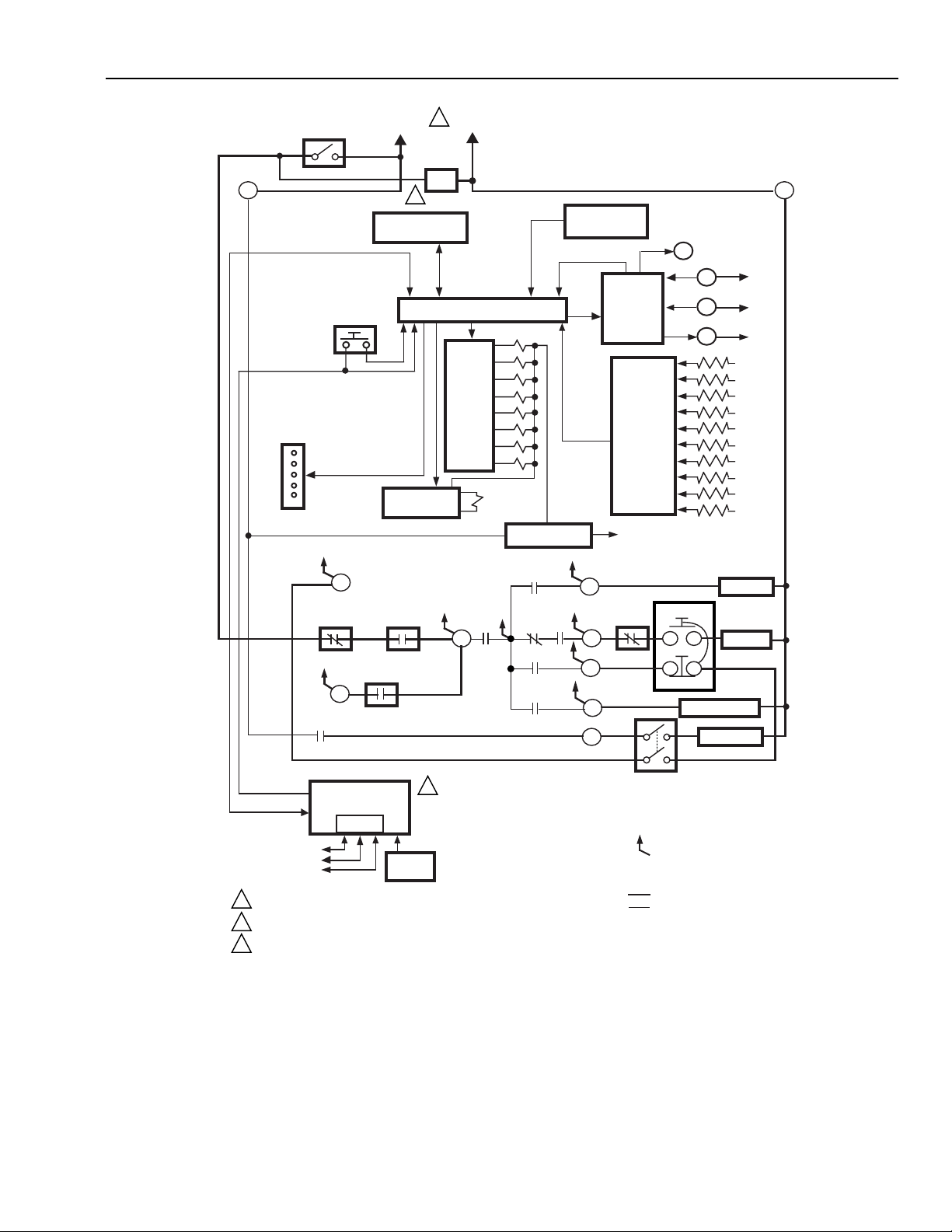
Fig. 1. Internal block diagram of the RM7838A (see Fig. 2 for detailed wiring instructions).
3
66-1087—2
Page 4
RM7838A 7800 SERIES RELAY MODULES
5. For recommended wire size and type, see Table 1.
6. For recommended grounding practices, see Table 2.
7. For keyboard display module (KDM). The KDM is
powered from a low voltage, energy-limited source.
It can be mounted outside of a control panel if it is
protected from mechanical damage.
NOTE: A 13 Vdc power supply must be used any
time more than one keyboard display
module is used. A maximum of two
keyboard display modules, Data ControlBus
Modules™ or S7810B Multi-Drop Switch
Modules are allowed in any combination.
9. Be sure loads do not exceed the terminal ratings. Refer
to the label on the RM7838A or to the terminal ratings
in Table 3.
10. The keyboard display module, Data ControlBus
Module™ (for remote mounting or communications) or
8. Maximum wire lengths:
a. RM7838A leadwires: The maximum leadwire
length is 300 feet (91 meters) to terminal inputs
(Control, Running Interlock, High Fire Switch and
Low Fire Switch).
b. Flame detector leadwires: The maximum flame
sensor leadwire length is limited by the flame
signal strength.
Communication Interface ControlBus Module must be
wired in a daisy chain configuration, (1(a)-1(a), 2(b)2(b), 3(c)-3(c)). The order of interconnection of all the
devices listed above is not important. Be aware that
modules on the closest and farthest end of the daisy
chain configuration string require a 120 ohm (1/4 watt
minimum) resistor termination across terminals
1 and 2 of the electrical connectors for connections
over 100 feet (30.5m).
Table 1. Recommended Wire Size and Part Numbers.
Application Recommended Wire Size Recommended Part Numbers
Line voltage terminals 14, 16, or 18 AWG copper conductor,
600 volt insulation wire.
Keyboard Display Module 22 AWG two-wire twisted pair with ground,
or five-wire.
Data ControlBus Module™ 22 AWG two-wire twisted pair with ground,
or five-wire.
Remote Reset Module 22 AWG two-wire twisted pair, insulated for
low voltage.
Comunications Interface
22 AWG two-wire twisted pair with ground. Belden 8723 shielded cable or equivalent.
ControlBus™ Module
13 Vdc full wave rectified
transformer power input.
18 AWG wire insulated for votlages and
temperatures for given application.
c. Remote reset leadwires: The maximum length of
wire is 1000 feet (305 meters) to a remote reset
pushbutton.
d. Data ControlBus Module™: The maximum Data
ControlBus Module™ cable length depends on the
number of system modules connected, the noise
conditions and the cable used. The maximum
length of all Data ControlBus Module™
interconnecting wire is 4000 feet (1219 meters).
TTW60C, THW75C, THHN90C
Belden 8723 shielded cable or equivalent.
Belden 8723 shielded cable or equivalent.
—
TTW60C, THW75C, THHN90C
Table 2. Recommended Grounding Practices.
Ground type Recommended Practice
Earth ground (subbase and relay module). 1. Use to provide a connection between the subbase and the control
panel of the equipment. Earth ground must be capable of
conducting enough current to blow the 20A fuse (or breaker) in the
event of an internal short circuit.
2. Use wide straps or brackets to provide minimum length, maximum
surface area ground conductors. If a leadwire must be used, use
14 AWG copper wire.
3. Make sure that mechanically tightened joints along the ground path
are free of nonconductive coatings and protected against corrosion
on mating surfaces.
Signal ground (Keyboard Display Module,
Data Controlbus Module™, Communications
Interface ControlBus™ Module).
66-1087—2
Use the shield of the signal wire to ground the device to the signal
gorund terminals [3(c)] of each device. Connect the shield at both ends
of the daisy chain to earth ground.
4
Page 5

RM7838A 7800 SERIES RELAY MODULES
Table 3. Terminal Ratings.
Terminal No. Description Ratings
GFlame Sensor Ground
Earth G Earth Ground
L2(N) Line Voltage Common —
3 Alarm 120 Vac, 1A pilot duty.
4 Line Voltage Supply (L1) 120 Vac, (+10/-15%), 50/60- Hz (±10%)
5 Unused —
6 Start/Stop Switch Input 120 Vac, 1 mA.
7 Running Interlock 120 Vac, 8A run, 43A inrush.
8 Intermittent Pilot 120 Vac.
9 Main Fuel Valve 120 Vac.
10 Ignition 120 Vac.
F(11) Flame Sensor 60 to 220 Vac, current limited.
12-18 Unused. —
19 High Fire Switch Input 120 Vac, 1 mA.
20 Unused —
21 Run Enable/Flame Proven 120 Vac, 2A pilot duty.
22 Shutter 120 Vac, 0.5A.
a
See Table 2.
b
2000VA maximum connected load.
c
See Tables 4 and 5.
1
a
—
—
c
c
c
b
Table 4. Combinations for Terminals 8, 9 and 10.
Combination No. Pilot Fuel 8 Main 9 Ignition 10
1CFNo Load
2BFNo Load
4FFA
5FNo Load A
6DFA
7DDA
8DNo Load A
Table 5. Composition of each Combination.
AB CDF
4.5A ignition 50 VA Pilot Duty plus 4.5A ignition. 180 VA Ignition plus
Motor valves with:
2A Pilot Duty 65 VA Pilot Duty plus
Motor valves with:
660 VA inrush,
360 VA open,
250 VA hold.
Final Wiring Check
1. Check the power supply circuit. The voltage and
frequency tolerance must match those of the RM7838A.
A separate power supply circuit can be required for the
RM7838A. Add the required disconnect means and
2. Check all wiring circuits and complete Static Checkout
in Table 7 before installing the RM7838A on the
subbase.
3. Install all electrical connectors.
4. Restore panel power.
overload protection.
3850 VA inrush,
700 VA open,
250 VA hold.
5
66-1087—2
Page 6

RM7838A 7800 SERIES RELAY MODULES
STATIC CHECKOUT
After checking all wiring, perform this checkout before
installing the RM7838A on the subbase. These tests verify
that the Q7800 Wiring Subbase is wired correctly and that the
external controllers, limits, interlocks, actuators, valves,
transformers, motors and other devices are operating
properly.
WARNING
Explosion Hazard.
Can cause explosion, electrical shock or
equipment damage.
1. Close all manual fuel shutoff valves before
starting these tests.
2. Use extreme care while testing the system. Line
voltage is present on most terminal connections
when power is on.
3. Open the master switch before installing or
removing a jumper on the subbase.
4. Before continuing to the next test, be sure to
remove test jumpers used in the previous test.
5. Replace all limits and interlocks that are not
operating properly. Do not bypass limits and
interlocks.
CAUTION
Equipment Damage Hazard.
Can cause equipment damage.
Do not perform a dielectric test with the RM7838A
installed. Internal surge protectors will break down
and conduct a current. This can cause the RM7838A
to fail the dielectric test or possibly destroy the internal
lightning and high current protection.
Equipment Recommended
1. Voltmeter (1M ohm/volt minimum sensitivity) set on the
0 to 300 Vac scale.
2. Two jumper wires, No. 14 wire, insulated, 12 in.
(304.8 mm) long with insulated alligator clips at both
ends.
General Instructions
1. Perform all applicable tests listed in Static Checkout,
Table 7, in the order listed.
2. Make sure all manual fuel shutoff valves are closed.
3. Raise the setpoint of the operating controller to simulate
a call for heat.
4. For each test, open the master switch and install the
jumper wires between the subbase wiring terminals
listed in the Test Jumpers column.
5. Close the master switch before observing operation.
6. Read the voltage between the subbase wiring terminals
listed in the Voltmeter column.
7. If there is no voltage or the operation is abnormal,
check the circuits and external devices as described in
the last column.
8. Check all wiring for correct connections, tight terminal
screws, correct wire and proper wiring techniques.
9. Replace all damaged or incorrectly sized wires.
10. Replace faulty controllers, limits, interlocks, actuators,
valves, transformers, motors and other devices as
required.
11. Make sure normal operation is obtained for each
required test before continuing the checkout.
12. After completing each test, be sure to remove the test
jumpers.
WARNING
Explosion Hazard.
Can cause serious injury or death.
Be sure all manual fuel shutoff valves are closed.
Table 7. Static Checkout.
Test
No. Test Jumpers Voltmeter Normal Operation
1 None 4-L2 Line voltage at terminal 4. 1. Master switch.
2 4-21 6-L2 Line voltage at terminal 6. 1. Stop station.
3 4-10 — Push Start pushbutton and
ignition sparks.
4 4-8 — Automatic pilot valve opens. 1. Listen for click or feel head of valve for
5 4-9 — Automatic main fuel valve(s)
opens.
6 4-3 — Alarm (if used) turns on. 1. Alarm.
2. Power connected to the master switch.
3. Overload protection (fuse, circuit breaker,
etc.) has not opened the power line.
2. Alarm silencing relay.
1. Watch for spark or listen for buzz.
a. Ignition electrodes are clean.
b. Ignition transformer is okay.
c. Damper not at low fire position.
d. Low Fire Switch.
activation.
a. Actuator if used.
b. Pilot valve.
1. Listen for and observe operation of the main
fuel valve(s) and actuator(s).
2. Valve(s) and actuator(s).
If Operation is Abnormal,
Check the Items Listed Below
(continued)
66-1087—2
6
Page 7

RM7838A 7800 SERIES RELAY MODULES
Table 7. Static Checkout (continued).
Test
No. Test Jumpers Voltmeter Normal Operation
7 May need to
jumper limits
and/or Running
Interlocks
FINAL ALL
19-L2 Manually drive damper motor
open and look for High Fire
Switch closure.
CAUTION
Equipment Damage Hazard.
Can cause equipment damage.
After completing these tests, open the master switch and remove all test jumpers from
the subbase terminals. Also remove bypass jumpers from limits if used.
Mounting RM7838A Relay Module
1. Mount the RM7838A on the 7800 Subbase vertically,
or mount horizontally with the knife blade terminals
pointing down. When mounted on the Q7800A, the
RM7838A must be in an electrical enclosure.
2. When mounted in an electrical enclosure, provide
adequate clearance for servicing, installation and
removal of the RM7838A, keyboard display module,
flame amplifier, signal probes, electrical signal
voltage probes and electrical connections.
a. Allow an additional two inches (51 mm) below
the RM7838A for the flame amplifier mounting.
b. Allow an optional three-inch (76 mm) minimum
to both sides of the RM7838A for electrical
signal voltage probes.
3. Make sure no subbase wiring is projecting beyond the
terminal blocks. Tuck in wiring against the back of the
subbase so it does not interfere with the knife blade
terminals or bifurcated contacts.
If Operation is Abnormal,
Check the Items Listed Below
1. High Fire Switch.
2. Firing rate motor and transformer.
3. Burner control.
4. Limits.
5. Running Interlocks.
IMPORTANT
The RM7838A must be installed with a plug-in
motion rather than a hinge action.
4. Mount the RM7838A by aligning the four L-shaped
corner guides and knife blade terminals with the
bifurcated contacts on the wiring subbase and securely
tightening the two screws without deforming the plastic.
Mounting Other System Components (Fig. 3)
Refer to the applicable specifications for mounting other
system components.
7
66-1087—2
Page 8

RM7838A 7800 SERIES RELAY MODULES
L1
(HOT)
L2
ALTERNATE CONNECTION WHEN
USING THE R4155A ALARM
SILENCING RELAY. THE
REMAINING CONNECTIONS ARE
THE SAME FOR THE RM7838A.
R4155A
2
120V ALARM
FOR DIRECT SPARK IGNITION
(OIL OR GAS)
8
1
56
STOP
B
A
MAIN FUEL
VALVES
MASTER
SWITCH
4
S445A
Q7800
SUBBASE
L1
3
6
21
L2
BURNER
CONTROL
FAN
4
120V ALARM
DPST ALARM
SILENCING
SWITCH
LIMITS
S445A
START
D
C
A
B
STOP
IGNITION
RUNNING
INTERLOCKS
PILOT
MAIN FUEL
VALVE(S)
LOW FIRE
PURGE SWITCH
FLAME
DETECTOR
3
3
5
Q7800 SUBBASE
(L1)
12
13
14
15
16
17
18
19
20
21
22
G
L2
3
4
5
6
7
8
9
10
F
2
HIGH FIRE
PURGE
SWITCH
VFD
DISPLAY
LED
DISPLAY
BURNER
START
OPERATING
CONTROLS
AND
INTERLOCKS
FLAME
SIGNAL
120V, 50/60 Hz POWER SUPPLY. PROVIDE DISCONNECT
1
MEANS AND OVERLOAD PROTECTION AS REQUIRED.
2
EXTERNAL ISOLATION REQUIRED OF INPUT AND
OUTPUT TERMINALS TO CONNECT THE RM7838A IN A
PARALLEL APPLICATION.
INITIATE
STANDBY
00 00 00 10
PURGE
POWERPOWER
7
TO
SAFE START CHECK
POWER
COMBUSTION BLOWER, RECIRCULATING, EXHAUST FANS
RUNNING INTERLOCKS AND BURNER CONTROLLER CLOSED
HIGH FIRE SW.
19
Fig. 2. Wiring subbase and sequence chart for RM7838A Relay Module.
RM7838A
HOLD
4 OR 10 SEC
POWER
PILOT
FLAME
MAIN
ALARMALARM ALARM ALARM ALARM
10
3
ISOLATION CONTACT REQUIRED FOR STANDING PILOT
APPLICATION. DRIVE 120 VAC RELAY FROM TERMINAL 8.
4
COMBUSTION BLOWER OR EXHAUST RECIRCULATING FANS.
SEE FLAME DETECTOR SPECIFICATION FOR CORRECT WIRING.
5
PFEP
START/IGN.
INTERMITTENT PILOT
STOP SWITCH
RUN
POWER POWER
PILOT
FLAME
MAIN
POWER
PILOT
FLAME
MAIN
ALARM
MAIN VALVE
L1
TO
FLAME PROVING
STANDBY
8
9
7
TO
621
ALARM
SSC
M11498B
66-1087—2
8
Page 9

SEQUENCE
STATUS
LED PANEL
PURGE
TIMER
RELAY
MODULE
CONFIGURATION
JUMPERS
RUN/TEST
SWITCH
WIRING
SUBBASE
RM7838A 7800 SERIES RELAY MODULES
HONEYWELL
POWER
PILOT
FLAME
MAIN
ALARM
RESET
KEYBOARD
DISPLAY
MODULE
RESET
BUTTON
SCROLL
BURNER CONTROL
MODE
- SAVE -
Fig. 3. RM7838A Relay Module exploded view.
PRINCIPAL TECHNICAL FEATURES
The RM7838A provides all customary flame safeguard
functions as well as significant advancements in safety,
annunciation, and system diagnostics.
Safety Shutdown (Lockout) Occurs If:
1. INITIATE Period
a. Purge card is not installed or removed.
b. Purge card is bad.
c. Configuration jumper was changed (after 200
hours).
d. AC line power errors, see Operation.
e. Four minute INITIATE period is exceeded.
2. STANDBY Period
a. Flame signal is present after 40 seconds.
b. Intermittent pilot valve/ 1st stage oil terminal is
energized.
c. Start Switch terminal energized.
d. Main valve terminal is energized.
e. Internal system fault.
CAPTIVE
MOUNTING
SCREW
FLAME
AMPLIFIER
M12300
f. Purge card is not installed or removed.
g. Purge card is bad.
h. Flame detected during the last two seconds.
3. PURGE Period
a. Flame signal detected during PURGE .
b. High fire switch fails to close within four minutes,
15 seconds after the burner switch, limit and
interlock string is closed.
c. Intermittent pilot valve/1st stage oil terminal is
energized.
d. Main valve terminal is energized.
e. Internal system fault.
f. Purge card is removed.
g. Purge card is bad.
h. Start Switch terminal is energized.
4. PILOT FLAME ESTABLISHING Period (PFEP)
a. Intermittent pilot valve/1st stage oil terminal is not
energized.
b. No flame is present at end of PFEP.
c. Internal system fault.
d. Purge card is not installed or removed.
e. Purge card is bad.
f. Main valve terminal is energized.
9
66-1087—2
Page 10

RM7838A 7800 SERIES RELAY MODULES
5. RUN Period
a. Intermittent pilot valve/1st stage oil terminal is not
energized.
b. Main valve terminal is not energized.
c. No flame is present.
d. Main valve terminal is de-energized.
e. Internal system fault.
f. Purge card is removed.
g. Purge card is bad.
OPERATION
Sequence of Operation
The RM7838A has the operating sequence listed below; see
Fig. 2. The RM7838A LEDs provide visual indication of the
program sequence: POWER, PILOT, FLAME, MAIN and
ALARM and are displayed on the Keyboard Display Module.
Initiate
The RM7838A enters the INITIATE sequence when the relay
module is initially powered. The RM7838A can also enter the
INITIATE sequence if the relay module verifies voltage
fluctuations of +10/-15% or frequency fluctuations of ±10%
during any part of the operating sequence. The INITIATE
sequence lasts for ten seconds unless the voltage or
frequency tolerances are not met. When the tolerances are
not met, a hold condition is initiated and displayed on the
KDM for at least five seconds. When the tolerances are met,
the INITIATE sequence restarts. If the condition is not correct
and the hold condition exists for four minutes, the RM7838A
locks out.
Causes for hold conditions in the INITIATE sequence include:
a. AC line dropout is detected.
b. AC line noise that can prevent a sufficient reading of the
line voltage inputs.
c. Brownouts caused by low line voltage.
The alarm, terminal 3, is energized during INITIATE.
Standby
The RM7838A is ready to start an operating sequence. When
the Burner Switch is closed, the Blower/Combustion Fan is
powered. The Airflow Switch closes and provides power to
terminal 7 through any additional limits or interlocks.
After terminal 7 is energized, "Safe Start Check" is displayed
on the KDM as the RM7838A transitions from Standby to
Purge. During safe start check, the RM 7838A verifies that
the flame detection system and all components are not in a
flame simulating condition. On applications using a shutter,
the shutter is energized to make sure no flame is present.
The alarm, terminal 3, is energized all the time the system is
in standby.
Normal Start-Up Purge
Closing the burner control switch energizes the combustion fan
and provides power to terminal 7 through all limits and
interlocks. Powering terminal 7 with all the microcomputer
monitored circuits in the correct state, the relay module begins
the PURGE sequence.
Purge Hold T19 (High Fire Switch) is displayed until the High
Fire Switch is proven.
PURGE timing begins when the damper motor is manually
driven to the High Fire Purge position and the High Fire Switch
is energized. Four minutes and 15 seconds are provided to
drive the damper to the fully open position. A jumpered or
welded High Fire Switch adds a 30 second hold to the
beginning of purge timing. When PURGE timing is complete,
“PILOT:HOLD:T6 (Start Switch)” is displayed on the KDM.
Ignition Trials
1. Pilot Flame Establishing Period (PFEP):
a. With the damper motor manually driven to the Low
Fire position:
(1) Press the START pushbutton and the ignition
transformer is energized with power from
terminal 10. Power is also applied to terminal 6
through the Start/Stop Switch internal jumper.
The STOP Switch and the Alarm Silencing
Switch. The RM7838A then energizes the
Intermittent Pilot valve (terminal 8).
(2) During PFEP, the Low Fire Switch and the
START switch must remain closed. If one
opens before the flame is proven, the pilot
valve shuts off , but the pilot flame establishing
timer continues to time.
b. Flame must be proven by the end of the ten-
second PFEP (four if configuration JRI jumper is
removed) to allow the sequence to continue. If
flame is not proven by the end of PFEP, a safety
shutdown occurs.
c. With flame proven, terminal 21 outputs line voltage
to maintain the input to terminal 6, which allows the
Start Switch to be released and the ignition to be
shut off.
NOTE: Terminal 10 verifies that the Start Switch is
released. If the Start Switch is not
released, a shutdown occurs.
d. Alarm LED and terminal 3 are turned off when
flame is detected.
Run
1. When the flame is proven, the FLAME LED lights and the
ALARM LED turns off. Release the Start push-button and
the ignition transformer shuts off. At the end of PFEP, the
RM7838A proceeds to the RUN period by energizing the
main valve, terminal 9, and the MAIN status LED on the
relay module.
2. The firing rate damper motor can now be positioned to
meet the setpoint of the process controller.
3. The RM7838A is in RUN and remains in RUN until the
STOP pushbutton is pushed, or a limit opens terminal 7.
4. The alarm, terminal 3, is de-energized during RUN and
energized when shutdown occurs.
Selectable PURGE timing from two seconds to 30 minutes is
available for the RM7838A.
66-1087—2
10
Page 11

Keyboard Display Module (KDM)
SELECTABLE CONFIGURATION JUMPER
M11502
The Keyboard Display Module (see Fig. 3) is provided with
the RM7838A Relay Module. The first line of the Vacuum
Fluorescent Display (VFD) provides:
1. Current status of the burner sequence (STANDBY,
PURGE, PILOT IGN, MAIN IGN and RUN).
2. Timing information (PURGE, PILOT IGN, and MAIN
IGN) in minutes and seconds.
3. Hold information (PURGE HOLD:T19).
4. Lockout information (Lockout, Fault Code, Message and
Sequence).
The extreme right side of the first line is either blank or shows
a small arrow pointing to the second line followed by a twoletter code (DI, Diagnostic Information; Hn, Fault History
Information; EA, Expanded Annunciator). When the arrow and
two-letter codes are displayed, it indicates the second line is
showing a selectable message submenu. The second line
displays selectable or pre-emptive messages.
A selectable message supplies information for flame strength,
system status indication, system or self-diagnostics and
troubleshooting.
A pre-emptive message has parentheses around the
message and supplies a detailed message to support the
sequence status information. A pre-emptive message can
also be a lockout message. A pre-emptive message replaces
a selectable message to support the sequence status
information. It also replaces a selectable message after
60 seconds or if a lockout message is available.
RM7838A 7800 SERIES RELAY MODULES
Fig. 4. Selectable site-configurable jumper.
Table 6. Site-Configurable Jumper Options.
Jumper
Number Description Intact Clipped
JR1 Pilot Flame Establishing
Period (PFEP)
SERVICE NOTE: Clipping and removing a site-cofigurable-
jumper enhances the level of safetyand
removing a site-configurable-jumper after
200 hours of operation causes a nonresettable fault 110.
10
seconds4seconds
SETTINGS AND ADJUSTMENTS
Selectable Sit-Configurable Jumpers
The RM7838A has one site-configurable jumper option, see
Fig. 4 and Table 6. If necessary, the site configurable jumper
should be clipped with side cutters and the resistor removed
from the relay module.
11
66-1087—2
Page 12

RM7838A 7800 SERIES RELAY MODULES
Home and Building Control
Honeywell Inc.
Honeywell Plaza
P.O. Box 524
Minneapolis MN 55408-0524
66-1087—2
66-1087—2 R.R. Rev. 8-98
Home and Building Control
Honeywell Limited-Honeywell Limitée
155 Gordon Baker Road
North York, Ontario
M2H 3N7
Printed in U.S.A. on recycled
paper containing at least 10%
post-consumer paper fibers.
12
www.honeywell.com
 Loading...