

Page 1

EC7830A, RM7830A, EC7850A, RM7850A
7800 SERIES Relay Modules
INSTALLATION INSTRUCTIONS
APPLICATION
The Honeywell EC/RM7830A and EC/RM7850A are
microprocessor-based integrated burner controls for
automatically fired gas, oil, or combination fuel single burner
full modulation (EC/RM7850A) or on/off (EC/RM7830A)
applications. The EC/RM7830A; EC/RM7850A system
consists of a relay module, subbase, amplifier, and purge
card. Options include keyboard display module (KDM),
Personal Computer Interface, Data ControlBus Module™,
remote display mounting and Combustion System Manager®
Software.
Functions provided by the EC/RM7830A and EC/RM7850A
include automatic burner sequencing, flame supervision,
system status indication, system or self-diagnostics and
troubleshooting. Text readout on the Keyboard Display Module
is available in English, Spanish, Portuguese, Katakana
(Japanese), French, Chinese, German, and Italian languages.
This document provides installation and static checkout
instructions. Other applicable publications are:
63-2278: Q7700 Network Interface Unit Product Data.
65-0084: Q7800A,B 22-Terminal Wiring Subbase
Product Data.
65-0090: S7800A Keyboard Display Module Product Data.
65-0091: S7810A Data ControlBus Module™ Product
Data.
65-0228: S7810B Multi-Drop Switch Module Product Data.
65-0095: S7820 Remote Reset Module Product Data.
65-0097: 221729C Dust Cover Packing Instructions.
65-0102: ZM7850A Combustion System Manager®
Operating Instructions.
65-0109: R7824, R7847, R7848, R7849, R7861, R7886
Flame Amplifiers for the 7800 SERIES
Product Data.
65-0131: 221818A Extension Cable Assembly Product
Data.
65-0229: 7800 SERIES Relay Modules Checkout and
Troubleshooting Product Data.
SPECIFICATIONS
Electrical Ratings (See Tables 3A, 3B, 3C and 3D):
Voltage and Frequency:
RM7830A and RM7850A:
120 Vac (+10/-15%), 50/60 Hz (±10%).
EC7830A and EC7850A:
220/240 Vac (+10%/-15%), 50/60 Hz (±10%)
Power Dissipation: 10W maximum.
Maximum Total Connected Load: 2000 VA.
Fusing Total Connected Load: 20A maximum, type FRN or
equivalent.
® U.S. Registered Trademark
Copyright © 1998 Honeywell Inc. • All Rights Reserved
Environmental Ratings:
Ambient T emperature:
Operating: -40°F to 140°F (-40°C to +60°C).
Storage: -40°F to 150°F (-40°C to +66°C).
Humidity: 85% relative humidity continuous,
noncondensing.
Vibration: 0.5G environment.
Approvals:
RM7830A and RM7850A:
Underwriters Laboratories Inc. Listed: File No. MP268,
Guide No. MCCZ.
Canadian Standards Association Certified: LR9S329-3.
Factory Mutual Approved: Report No. J.I.1V9A0.AF.
Industrial Risk Insurers: Acceptable.
Federal Communications Commission: Part 15,
Class B, Emissions.
EC7830A and EC7850A: Factory Mutual Approved.
These products also comply with the following European
directives:
Gas Appliance Directive: 90/396/EEC.
Low Voltage Directive: 73/23/EEC.
EMC Directive: 89/336/EEC.
GASTEC: CE-63AP3070/1.
Lloyds Register Approval.
Oil appliances:
EC7830A: DIN-5F 106/96.
EC7850A: DIN-5F 107/96.
These products are approved according to EN298, “Automatic
gas burner systems for gas burners and gas burning
appliances with or without fans.”
Please note the following to comply with EN60730 for remote
mounting of the KDM and/or remote reset module. It is
necessary to provide electrical separation using insulation at
least equivalent to double or reinforced insulation. This can be
accomplished by either:
1. Optically isolating the communication and/or remote
reset lines from the control cabinet or
2. Providing physical separation from the communication
and/or remote reset lines using electrical conduit and a
204718a Remote Display Cover Assembly or other
suitable enclosure that meets ip40 class of protection.
66-1092-2
Page 2

EC7830, RM7830A,EC7850A,RM7850A 7800 SERIES RELAY MODULES
INSTALLATION
When Installing this Product…
1. Read these instructions carefully. Failure to follow them
could damage the product or cause a hazardous
condition.
2. Check the ratings given in the instructions and marked
on the product to make sure the product is suitable for
the application.
3. Installer must be a trained, experienced, flame
safeguard service technician.
4. After installation is complete, check out the product
operation as provided in these instructions.
WARNING
Fire or Explosion Hazard.
Can cause property damage,
severe injury, or death.
Carefully follow safety requirements when installing a
burner control.
CA UTION
Electrical Shock Hazard or Equipment/
Control Damage.
Can cause electrical shock or equipment damage.
Disconnect power supply before beginning
installation.
IMPORTANT
1. Wiring connections for the relay modules are unique;
refer to Fig. 3 and 4 or the appropriate Specifications
for individual subbase wiring.
2. Wiring must comply with all applicable codes,
ordinances and regulations.
3. Wiring must comply with NEC Class 1
(Line Voltage) wiring.
4. Loads connected to the EC/RM7830A and
EC/RM7850A must not exceed those listed on the
relay module label or the Specifications; see Table 1.
5. Limits and interlocks must be rated to
simultaneously carry and break current to the
ignition transformer, pilot valve, and main fuel
valve(s).
6. All external timers must be listed or componentrecognized by authorities who have proper
jurisdiction.
7. For on-off gas-fired systems, some authorities who
have jurisdiction prohibit the wiring of any limit or
operating contacts in series between the flame
safeguard control and the main fuel valve(s).
8. Two flame detectors can be connected in parallel
with the exception of C7015 Infrared Flame
Detectors.
9. This equipment generates, uses and can radiate
radio frequency energy and, if not installed and used
in accordance with the instructions, can cause
interference with radio communications. It has been
tested and found to comply with the limits for a Class
B computing device of Part 15 of FCC rules, which
are designed to provide reasonable protection
against such interference when operated in a
commercial environment. Operation of this
equipment in a residential area can cause
interference, in which case, the users, at their own
expense, may be required to take whatever
measures are required to correct this interference.
10. This digital apparatus does not exceed the Class B
limits for radio noise for digital apparatus set out in
the Radio Interference Regulations of the Canadian
Department of Communications.
Location
Humidity
Install the relay module where the relative humidity never
reaches the saturation point. The relay module is designed to
operate in a maximum 85% relative humidity continuous,
noncondensing, moisture environment. Condensing moisture
can cause a safety shutdown.
Vibration
Do not install the relay module where it can be subjected to
vibration in excess of 0.5G continuous maximum vibration.
Weather
The relay module is not designed to be weather tight. When
installed outdoors, protect the relay module in an approved
weather-tight enclosure.
Mounting Wiring Subbase
1. Mount the subbase in any position except horizontally
with the bifurcated contacts pointing down. The
standard vertical position is recommended. Any other
position decreases the maximum ambient temperature
rating.
2. Select a location on a wall, burner or electrical panel.
The Q7800 can be mounted directly in the control
cabinet. Be sure to allow adequate clearance for
service, installation, access or removal of the relay
module, expanded annunciator, KDM, flame amplifier,
flame amplifier signal voltage probes, run/test switch,
electrical signal voltage probes and electrical field
connections.
3. For surface mounting, use the back of the subbase as a
template to mark the four screw locations, then drill the
pilot holes.
4. Securely mount the subbase using four no. 6 screws
(not provided).
66-1092—2
2
Page 3
EC7830, RM7830A,EC7850A,RM7850A 7800 SERIES RELAY MODULES
Wiring Subbase
CAUTION
Electrical Shock Hazard or Equipment Damage.
Can cause electrical shock or damage equipment.
Disconnect the power supply before beginning
installation.
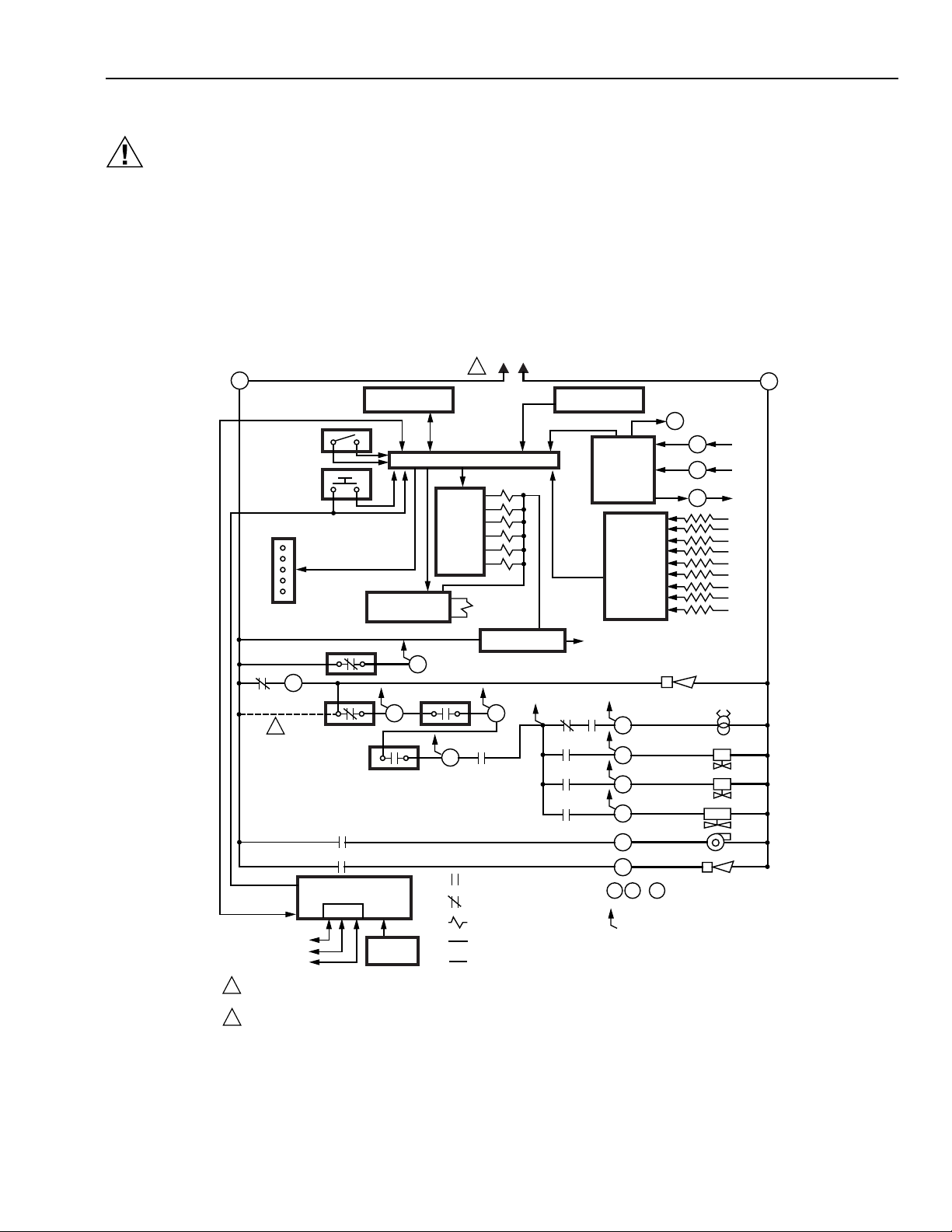
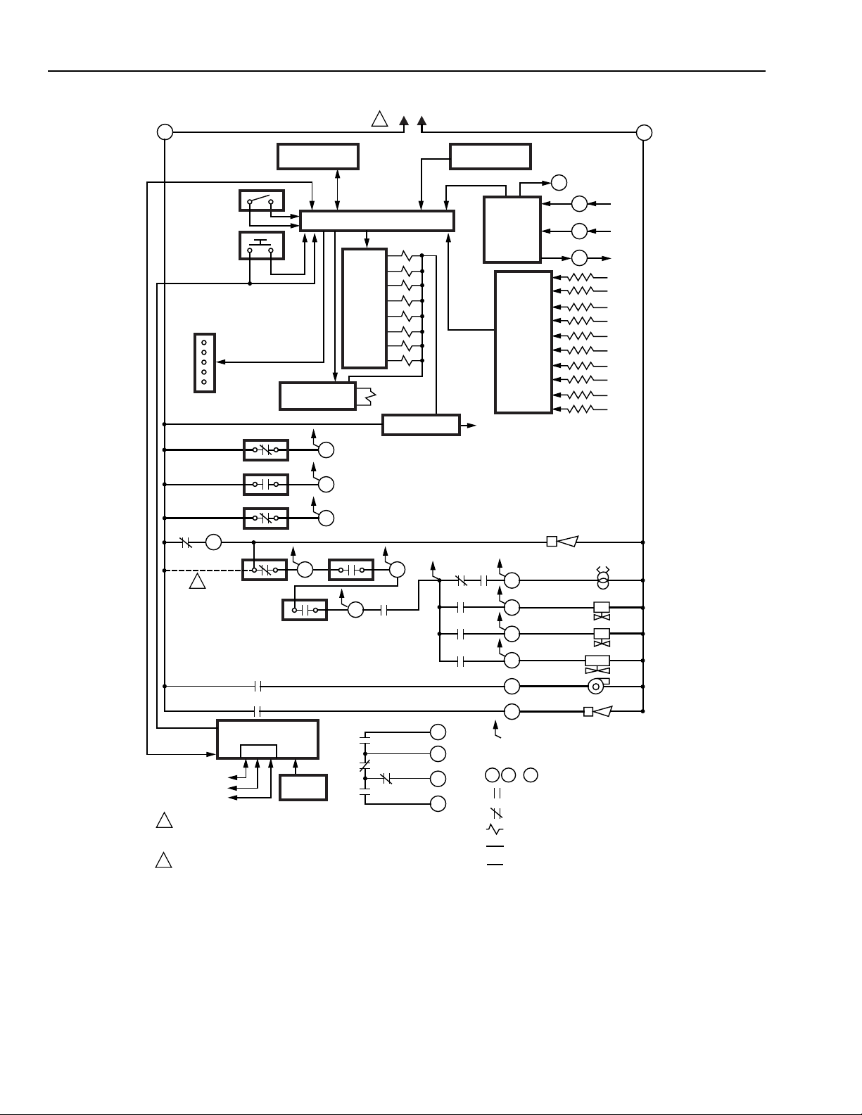
The internal block diagram of the EC/RM7830A is shown in
Fig. 1 and the internal block diagram of the EC/RM7850A is
shown in Fig. 2.
1. For subbase wiring and sequence charts, refer to Fig. 3
and 4.
5
CONFIGURATION
JUMPERS
RUN/TEST
SWITCH
MICROCOMPUTER
RESET
PUSHBUTTON
RELAY
DRIVE
CIRCUIT
ES2
6K1
3K1
RS485
2
SAFETY RELAY
CIRCUIT
20 6
LD2
5
REMOTE
RESET
3
17
RTLOS
7
STATUS
LEDS
3K2
16
2
OPTIONAL KEYBOARD
DDL
DDL
COMMUNICATIONS
1
120 VAC, 50/60 Hz POWER SUPPLY, RM7830A; 220-240 VAC, 50/60 Hz POWER SUPPLY, EC7830A.
PROVIDE DISCONNECT MEANS AND OVERLOAD PROTECTION AS REQUIRED.
2
TO CONNECT L1 DIRECTLY TO LOS, AT LEAST ONE CONTROLLED SHUTDOWN MUST BE PROVIDED EVERY 24 HOURS.
DISPLAY MODULE
1
Fig. 1. Internal block diagram of EC/RM7830A (see Fig. 3 for detailed wiring instructions).
2. For remote wiring of the KDM, refer to the
Specifications for the KDM (65-0090), Network
Interface Unit (63-2278), Data ControlBus Module™
(65-0091) or Extension Cable Assembly (65-0131).
3. Disconnect the power supply from the main disconnect
before beginning installation to prevent electrical shock
and equipment damage. More than one disconnect can
be required.
4. All wiring must comply with all applicable electrical
codes, ordinances and regulations. Wiring, where
required, must comply with NEC Class 1 (Line Voltage)
wiring.
5. For recommended wire size and type, see Table 1.
6. For recommended grounding practices, see Table 2.
L1
HOT
N
1
PLUG-IN PURGE
TIMER CARD
FLAME SIGNAL
2K
3K
4K
5K
6K
7K
1K
POWER SUPPLY
2K2 5K1
1K1
RELAY CONTACT OPEN
RELAY CONTACT CLOSED
RELAY COIL
FIELD WIRING
INTERNAL WIRING
4K1
7K1
2K1
PLUG-IN
FLAME
AMPLIFIER
RELAY
STATUS
FEEDBACK
AND LINE
VOLTAGE
INPUTS
CONTROL
POWER
AL
10
8
21
9
4
3
F G ... 22
INDICATES FEEDBACK SENSING
OF RELAY CONTACT STATUS
AND LINE VOLTAGE INPUTS
USER TERMINALS
TEST
JACK
F
G
22
2
SHUTTER
IGN
PV1
PV2
MV
FAN
AL
M15183B
3
66-1092—2
Page 4
EC7830, RM7830A,EC7850A,RM7850A 7800 SERIES RELAY MODULES
L1
N
HOT
RELAY
DRIVE
CIRCUIT
RTLOS
7
8K1
8K2
9K2
1
2K
3K
4K
5K
6K
7K
8K
9K
1K
POWER SUPPLY
1K1
HIGH FIRE
COMMON
LOW FIRE
9K1
MODULATE
PLUG-IN PURGE
TIMER CARD
FLAME SIGNAL
2K2 5K1
4K1
7K1
2K1
12
13
15
14
PLUG-IN
FLAME
AMPLIFIER
RELAY
STATUS
FEEDBACK
AND LINE
VOLTAGE
INPUTS
CONTROL
POWER
F G ... 22
4
CONFIGURATION
JUMPERS
RUN/TEST
SWITCH
MICROCOMPUTER
RESET
PUSHBUTTON
ES1
ES3
ES2
6K1
3K1
RS485
2
SAFETY RELAY
CIRCUIT
20 6
LD2
5
REMOTE
RESET
3
18
19
17
STATUS
LEDS
3K2
16
2
OPTIONAL KEYBOARD
DISPLAY MODULE
DDL
DDL
COMMUNICATIONS
1
120 VAC, 50/60 Hz POWER SUPPLY, RM7850A; 220-240 VAC,
50/60 Hz POWER SUPPLY, EC7850A. PROVIDE DISCONNECT
MEANS AND OVERLOAD PROTECTION AS REQUIRED.
2
TO CONNECT L1 DIRECTLY TO LOS, AT LEAST ONE CONTROLLED
SHUTDOWN MUST BE PROVIDED EVERY 24 HOURS.
1
Fig. 2. Internal block diagram of EC/RM7850A (see Fig. 4 for detailed wiring instructions).
TEST
JACK
F
G
SHUTTER
22
AL
10
8
21
9
5
3
INDICATES FEEDBACK SENSING
OF RELAY CONTACT STATUS
AND LINE VOLTAGE INPUTS
USER TERMINALS
RELAY CONTACT OPEN
RELAY CONTACT CLOSED
RELAY COIL
FIELD WIRING
INTERNAL WIRING
IGN
PV1
PV2
MV
FAN
AL
M15184B
2
66-1092—2
4
Page 5

EC7830, RM7830A,EC7850A,RM7850A 7800 SERIES RELAY MODULES
L1
N
1
G 12
N 13
3 14
4 15
5 16
6 17
7 18
8 19
(L1)
9 20
10 21
F 22
AL
FAN
RT
LD2
PV1
MV
IGN
ES2
LOS
PV2
FLAME
DETECTOR
1
12O VAC, 50/60 Hz POWER SUPPLY (RM7830A). 220-240 VAC, 50/60 Hz POWER SUPPLY
(EC7830A). PROVIDE DISCONNECT MEANS AND OVERLOAD PROTECTION AS REQUIRED.
SEE FLAME DETECTOR INSTRUCTIONS FOR CORRECT WIRING.
LEGEND
ALARM
(NORMALLY OPEN)
PREIGNITION
INTERLOCK INPUT
BURNER/BLOWER
MOTOR
IGNITION
LINE VOLTAGE SUPPLY
LOCKOUT INPUT
AIRFLOW SWITCH INPUT
MAIN FUEL VALVE
PILOT VALVE 1
(INTERRUPTED)
PILOT VALVE 2
(INTERMITTENT)
LIMITS AND BURNER
CONTROL
AL
ES2
FAN
IGN
L1
LOS
LD2
MV
PV1
Q7800
2
2
INITIATE
POWER
PILOT
FLAME
MAIN
ALARM
STANDBY
RUN
STANDBY
PRE
IGNITION
PILOT
STABIL.
MAIN
STABIL.
IGNITION
BURNER
POSTPURGE
MAIN VALVE
LIMITS AND BURNER CONTROL CLOSED
LOCKOUT INPUT
10 sec
AIRFLOW SWITCH CHECK
PILOT VALVE
V2
PREIGNITION INTERLOCK
OPTIONS
SAFE START CHECK
FLAME PROVING
3 sec
5 sec
5 sec
1 IF ON AT CALL FOR HEAT, HOLD (120 sec). LOCK OUT IF STILL ON.
3 or 5 sec
3 or 5 sec
SAFE START CHECK
IF OFF AFTER 10 SEC OF FAN, LOCK OUT.
2
2, 15 or 30 sec
3
4
5
TAKE LOCKOUT ACTION, CONTINUE POSTPURGE TIMING.
SELECT VIA ST7800A PURGE TIMER CARD.
4
5
6
SELECT VIA CONFIGURATION JUMPERS OR MODEL NUMBERS.
AFS CHK
1
2 sec
AFS CHK
AFS CHK
DUE TO ONE EXTRA SECOND FOR SAFETY RELAY TEST, TIMING CAN VARY FROM 3 TO 4 SECONDS.
6
LED
DISPLAY
"PREPURGE"
WAITING
FIRST SAFETY
TIME
MAIN TRIAL
TIME
OPERATING
CONTROLS
AND
INTERLOCKS
FLAME
SIGNAL
EC/RM7830A Power Burner ON/OFF, GAS or OIL Sequence
2
3
6
6
M15185B
PV2
RT
8
21
9
6
20
7
10
17
BURNER/BLOWER MOTOR
4
Fig. 3. Wiring subbase and sequence chart for EC/RM7830A.
5
66-1092—2
Page 6

EC7830, RM7830A,EC7850A,RM7850A 7800 SERIES RELAY MODULES
SERIES 90
FIRING RATE
G 12
N 13
AL
FAN
RT
LD2
PV1
MV
IGN
2
FLAME
DETECTOR
120 VAC, 50/60 HZ POWER SUPPLY, RM7850A; 220-240 VAC, 50/60 HZ POWER SUPPLY, EC7850A.
1
2
SEE FLAME DETECTOR INSTRUCTIONS FOR CORRECT WIRING.
3 14
(L1)
4 15
5 16
6 17
7 18
8 19
9 20
10 21
F 22
HIGH FIRE
COMMON
MODULATE
LOW FIRE
ES2
ES1
ES3
LOS
PV2
MOTORQ7800
B
R
W
SERIES 90
CONTROLLER
B
R
W
1
L1
N
AL
ES1
ES2
ES3
FAN
IGN
L1
LOS
LD2
MV
PV1
PV2
RT
EC/RM7850A Power Burner Full Modulation, GAS or OIL Sequence
LED
DISPLAY
POWER
PILOT
FLAME
MAIN
ALARM
BURNER
INITIATE
STANDBY
PURGE
DRIVE
OR
TO HIGH
WAITING
FIRE
BURNER/BLOWER MOTOR
DRIVE
TO LOW
FIRE
PRE
IGNITION
IGNITION
FIRST
SAFETY
TIME
10
PILOT
STABIL.
MAIN
TRIAL
TIME
5
MAIN
STABIL.
LEGEND
ALARM
(NORMALLY OPEN)
LOW FIRE SWITCH
INPUT
PREIGNITION
INTERLOCK INPUT
HIGH FIRE SWITCH
INPUT
BURNER/BLOWER
MOTOR
IGNITION
LINE VOLTAGE SUPPLY
LOCKOUT INPUT
AIRFLOW SWITCH INPUT
MAIN FUEL VALVE
PILOT VALVE 1
(INTERRUPTED)
PILOT VALVE 2
(INTERMITTENT)
LIMITS AND BURNER
CONTROL
RUN
POSTPURGE
STANDBY
OPERATING
CONTROLS
AND
INTERLOCKS
AFS CHK
FLAME
SIGNAL
MOD
HF
LF
MOTOR
2 sec
OPTIONS
1 IF ON AT CALL FOR HEAT, HOLD (120 SEC). LOCK OUT IF STILL ON.
IF OFF AFTER 10 SEC OF FAN, LOCK OUT.
2
TAKE LOCKOUT ACTION. CONTINUE POSTPURGE TIMING.
3
SELECT VIA ST7800A PURGE TIMER CARD.
4
AFS CHK
PREIGNITION INTERLOCK
LIMITS AND BURNER CONTROL CLOSED
LOCKOUT INPUT
10 sec
2
1
SAFE START CHECK
AIRFLOW SWITCH CHECK
HF Sw
LF
4
Fig. 4. Wiring subbase and sequence chart for EC/RM7850A.
PILOT VALVE
V2
21
LF Switch
56
3 sec
3 or 5 sec 3 or 5 sec
DUE TO ONE EXTRA SECOND FOR SAFETY RELAY TEST,
5
TIMING CAN VARY FROM 3 TO 4 SEC.
SELECTION VIA CONFIGURATION JUMPERS OR MODEL NUMBERS.
6
8
21
FLAME PROVING
5 sec
MAIN VALVE
1819
6 6
5 sec
9
6
20
7
SAFE START CHECK
MODHF
2, 15 or 30 sec
3
AFS CHK
M15186B
66-1092—2
6
Page 7

EC7830, RM7830A,EC7850A,RM7850A 7800 SERIES RELAY MODULES
Table 1. Recommended Wire Sizes and Part Numbers.
Application Recommended Wire Size Recommended Part Numbers
Line voltage terminals 14, 16, or 18 AWG copper conductor, 600
KD M 22 AWG two-wire twisted pair with
Data ControlBus Module™ 22 AWG two-wire twisted pair with
Remote Reset Module 22 AWG two-wire twisted pair, insulated
Communication Interface
ControlBus™ Module
13 Vdc full-wave rectified
transformer power input
The KDM, Data ControlBus Module™ (for remote mounting or communications) or Communication Interface ControlBus™
Module must be wired in daisy chain configuration, 1(a)-1(a), 2(b)-2(b), 3(c)-3(c). The order of interconnection of all the devices
listed above is not important. Be aware that modules on the closest and farthest end of the daisy chain configuration string
require a 120 ohm (1/4 watt minimum) resistor termination across terminals 1 and 2 of the electrical connectors for connections
longer than 100 feet (31 meters).
volt insulation, moisture-resistant wire.
ground, or five-wire.
ground, or five-wire.
for low voltage.
22 AWG two-wire twisted pair with
ground.
18 AWG wire insulated for voltages and
temperatures for given application.
Table 2. Recommended Grounding Practices.
TTW60C, THW75C, THHN90C.
Belden 8723 shielded cable or
equivalent.
Belden 8723 shielded cable or
equivalent.
—
Belden 8723 shielded cable or
equivalent.
TTW60C, THW75C, THHN90C.
Ground type Recommended Practice
Earth ground (subbase and
relay module).
Signal ground (KDM, Data
ControlBus™ Module,
Communications Interface
ControlBus™ Module).
7. Recommended wire routing of leadwires:
a. Do not run high voltage ignition transformer wires
in the same conduit with the flame detector, Data
ControlBus Module™, or Remote Reset Module
wiring.
b. Do not route flame detector, Data ControlBus
Module™, or Remote Reset Module leadwires in
conduit with line voltage circuits.
c. Enclose flame detector leadwires without armor
cable in metal cable or conduit.
d. Follow directions in flame detector, Data
ControlBus Module™, or Remote Reset Module
Instructions.
8. The KDM is powered from a low voltage, energy limited
source. Mount the KDM outside of a control panel when
it is protected from mechanical damage.
1. Use to provide a connection between the subbase and the control panel of the
equipment. Earth ground must be capable of conducting enough current to blow the
20A fuse (or breaker) in the event of an internal short circuit.
2. Use wide straps or brackets to provide minimum length, maximum surface area ground
conductors. If a leadwire must be used, use 14 AWG copper wire.
3. Make sure that mechanically tightened joints along the ground path are free of
nonconductive coatings and protected against corrosion on mating surfaces.
Use the shield of the signal wire to ground the device to the signal ground terminals 3(c) of
each device. Connect the shield at both ends of the daisy chain to earth ground.
IMPORTANT
A 13 Vdc power supply must be used any time more
than one KDM is used. A maximum of two KDM,
Data ControlBus™ Modules or S7810B Multi-Drop
Switch Modules are allowed in any combination.
9. Maximum wire lengths:
a. EC/RM7830A and EC/RM7850A leadwires: The
maximum leadwire length is 300 feet (91 meters)
to terminal inputs (Control, Running/Lockout
Interlock).
b. Flame Detector leadwires: The maximum flame
sensor leadwire length is limited by the flame
signal strength.
c. Remote Reset leadwires: The maximum length of
wire is 1000 feet (305 meters) to a Remote Reset
pushbutton.
d. Data ControlBus Module™: The maximum Data
ControlBus Module™ cable length depends on
the number of system modules connected, the
noise conditions and the cable used. The
maximum length of all Data ControlBus Module™
interconnecting wire is 4000 feet (1219 meters).
10. Be sure loads do not exceed the terminal ratings. Refer
to the label on the relay module or to the terminal
ratings in Tables 3A, 3B, 3C and 3D.
Final Wiring Check
1. Check the power supply circuit. The voltage and
frequency tolerance must match those of the relay
module. (A separate power supply circuit can be
required for the relay module.) Add the required
disconnect means and overload protection.
2. Check all wiring circuits and complete the Static
Checkout in Table 4 or 5 before installing the relay
module on the subbase.
3. Install the relay module.
4. Restore power to the panel.
7
66-1092—2
Page 8

EC7830, RM7830A,EC7850A,RM7850A 7800 SERIES RELAY MODULES
Table 3A. RM7830A Terminal Ratings.
Terminal No. Abbreviation Description Ratings
G Flame Sensor Ground
Earth G Earth Ground
a
N Line Voltage Common
(Neutral)
3 AL Alarm (Normally Open) 120 Vac, 1A pilot duty, 10A inrush for 5000 cycles.
4 FAN Burner/Blower Motor 120 Vac, 4A at PF = 0.5, 20A inrush.
5 L1 Line Voltage Supply (L1) 120 Vac (+10/-15%), 50/60 Hz (±10%).
6 RT Limits and Burner Control 120 Vac, 1 mA.
7 LD2 Airflow Switch Input 120 Vac, 5A.
8 PV1 Pilot Valve 1 (Interrupted) 120 Vac, 4A at PF = 0.5, 20A inrush.
9 M V Main Fuel Valve 120 Vac, 4A at PF = 0.5, 20A inrush.
10 IGN Ignition 120 Vac, 2A at PF = 0.2.
F(11) Flame Signal 60 to 220 Vac, current limited.
16 Control Voltage 120 Vac (+10/-15%)
17 ES2 Preignition Interlock Input 120 Vac, 1A, 10A inrush for 5000 cycles.
20 LOS Lockout Input 120 Vac, 1 mA.
21 PV2 Pilot Valve 2 (Intermittent) 120 Vac, 4A at PF = 0.5, 20A inrush.
22 SHTR Shutter Shutter drive for dynamic self-check flame sensor.
a
See T able 2.
b
Honeywell has tested this output at 9.8A at PF = 0.5, 58.8A inrush for 100,000 cycles (EN298 approval does not require this
test).
c
2000 VA maximum connected load to relay module.
d
Total load current excluding Burner/Boiler Motor and Firing Rate Outputs cannot exceed 5A, 25A inrush.
a
b
c
d
d
d
Carry 5A for 250,000 cycles.
d
Table 3B. EC7830A Terminal Ratings.
Terminal No. Abbreviation Description Ratings
G Flame Sensor Ground
Earth G Earth Ground
a
a
N Line Voltage Common(Neutral)
3 AL Alarm(Normally Open) 220/230/240 Vac, 1A, 10 A inrush for 5000 cycles.
4 FAN Burner/Blower Motor 220/230/240 Vac, 4A at PF = 0.5, 20A inrush.
5 L1 Line Voltage Supply (L1) 220 to 240 Vac (+10/-15%), 50/60 Hz (±10%).
b
6 RT Limits and Burner Control 220/230/240 Vac, 1 mA maximum.
7 LD2 Airflow Switch Input 220/230/240 Vac, 5A.
8 PV1 Pilot Valve 1 (Interrupted) 220/230/240 Vac, 4A at PF = 0.5, 20A inrush.
9 MV Main Fuel Valve 220/230/240 Vac, 4A at PF = 0.5, 20A inrush.
10 IGN Ignition 220/230/240 Vac, 2A ignition.
c
c
c
F(11) Flame Signal 60 to 220 Vac, current limited.
16 Control Voltage 220/230/240 Vac, 1A, 10A inrush for 5000 cycles;
carry 5A for 250,000 cycles.
17 ES2 Preignition Interlock Input 220/230/240 Vac, 1 mA.
20 LOS Lockout Input 220/230/240 Vac, 1 mA.
21 P V2 Pilot Valve 2 (Intermittent) 220/230/240 Vac, 4A at PF = 0.5, 20A inrush.
c
22 SHTR Shutter Shutter drive for dynamic self-check flame sensor.
a
See T able 2.
b
2000 VA maximum connected load to relay module.
c
Total load current excluding Burner/Boiler Motor and Firing Rate Outputs cannot exceed 5A, 25A inrush for 250,000 cycles.
d
220/240 Vac to 120 Vac, 10 VA stepdown transformer (not provided) must be used to drive the shutter.
d
66-1092—2
8
Page 9

EC7830, RM7830A,EC7850A,RM7850A 7800 SERIES RELAY MODULES
Table 3C. RM7850A Terminal Ratings.
Terminal No. Abbreviation Description Ratings
G Flame Sensor Ground
Earth G Earth Ground
a
N Line Voltage Common(Neutral)
3 AL Alarm (Normally Open) 120 Vac, 1A, 10A inrush for 5000 cycles.
4 L1 Line Voltage Supply (L1) 120 Vac, (+10/-15%), 50/60 Hz (±10%).
5 FAN Burner/Blower Motor 120 Vac, 4A at PF = 0.5, 20A inrush.
6 RT Limits and Burner Control 120 Vac, 1 mA.
7 LD2 Airflow Switch Input 120 Vac, 5A.
8 PV1 Pilot Valve 1 (Interrupted) 120 Vac, 4A at PF = 0.5, 20A inrush.
9 MV Main Fuel Valve 120 Vac, 4A at PF = 0.5, 20A inrush.
10 IGN Ignition 120 Vac, 2A ignition.
F(11) Flame Signal 60 to 220 Vac, current limited.
12 HI Firing Rate High Fire 120 Vac, 0.5A at PF = 0.5.
13 COM Firing Rate Common 120 Vac, 0.5A at PF = 0.5.
14 MOD Firing Rate Modulate 120 Vac, 0.5A at PF = 0.5.
15 LO Firing Rate Low Fire 120 Vac, 0.5A at PF = 0.5.
16 Alarm (normally closed) 120 Vac, 1A, 10A inrush for 5000 cycles; carry 5A for
17 ES2 Preignition Interlock Input 120 Vac, 1 mA.
18 ES1 Low Fire Switch Input 120 Vac, 1 mA.
19 ES3 High Fire Switch Input 120 Vac, 1 mA.
20 LOS Lockout Input 120 Vac, 1 mA.
21 P V2 Pilot Valve 2 (Intermittent) 120 Vac, 4A at PF = 0.5, 20A inrush.
22 SHTR Shutter Shutter drive for dynamic self-check flame sensor.
a
See T able 2.
b
2000 VA maximum connected load to relay module.
c
Honeywell has tested this output at 9.8A at PF = 0.5, 58.8A inrush for 100,000 cycles
(EN298 approval does not require this test).
d
Total load current, excluding Burner/Boiler Motor and Firing Rate Outputs cannot exceed 5A, 25A inrush.
e
Can also be 24 Vac, 3A at PF = 0.5.
a
d
e
e
e
e
250,000 cycles.
b
c
d
d
s
9
66-1092—2
Page 10

EC7830, RM7830A,EC7850A,RM7850A 7800 SERIES RELAY MODULES
Table 3D. EC7850A Terminal Ratings.
Terminal No. Abbreviation Description Ratings
G Flame Sensor Ground
Earth G Earth Ground
N Line Voltage Common(Neutral)
3 AL Alarm (Normally Open) 220/230/240 Vac, 1A, 10A inrush for 5000 cycles.
4 L1 Line Voltage Supply (L1) 220 to 240 Vac (+10/-15%), 50/60 Hz ( ±10%).
5 FAN Burner/Blower Motor 220/230/240 Vac, 4A at PF = 0.5, 20A inrush.
6 RT Limits and Burner Control 220/230/240 Vac, 1 mA.
7 LD2 Airflow Switch Input 220/230/240 Vac, 5A.
8 PV1 Pilot Valve 1 (Interrupted) 220/230/240 Vac, 4A at PF = 0.5, 20A inrush.
9 MV Main Fuel Valve 220/230/240 Vac, 4A at PF = 0.5, 20A inrush.
10 IGN Ignition 220/230/240 Vac, 2A at PF = 0.2.
F(11) Flame Signal 136 to 220 Vac, current limited.
12 HI Firing Rate High Fire 220/230/240 Vac, 0.5A at PF = 0.5.
13 COM Firing Rate Common 220/230/240 Vac, 0.5A at PF = 0.5.
14 MOD Firing Rate Modulate 220/230/240 Vac, 0.5A at PF = 0.5.
15 LO Firing Rate Low Fire 220/230/240 Vac, 0.5A at PF = 0.5.
16 Alarm (normally closed) 220/230/240 Vac, 1A, 10A inrush for 6000 cycles;
17 ES2 Preignition Interlock Input 220/230/240 Vac, 1 mA.
18 ES1 Low Fire Switch Input 220/230/240 Vac, 1 mA.
19 ES3 High Fire Switch Input 220/230/240 Vac, 1 mA.
20 LOS Lockout Input 220/230/240 Vac, 1 mA.
21 P V2 Pilot Valve 2 (Intermittent) 220/230/240 Vac, 4A at PF = 0.5, 20A inrush.
22 SHTR Shutter Shutter drive for dynamic self-check flame sensor.
a
See T ab le 2.
b
2000 VA maximum connected load to relay module.
c
Total load current, excluding Burner/Boiler Motor and Firing Rate Outputs cannot exceed 5A, 25A inrush for 250,000 cycles.
d
Can also be 24 Vac, 3A at PF = 0.5.
e
220/240 Vac to 120 Vac, 10 VA stepdown transformer (not provided) must be used to drive the shutter.
a
a
carry 5A for 250,000 cycles.
b
c
c
c
d
d
d
d
c
e
Mounting EC/RM7830A;
EC/RM7850A Relay Module
1. Mount the relay module vertically on the Q7800
Subbase, or mount horizontally with the knife blade
terminals pointing down. When mounted on the
Q7800A, the relay module must be in an electrical
enclosure.
2. When mounting in an electrical enclosure, provide
adequate clearance for servicing, installation and
removal of the relay module, KDM, flame amplifier,
flame amplifier signal voltage probes, electrical signal
voltage probes and electrical connections.
a. Allow an additional 2 in. (51 mm) below the relay
module for the flame amplifier mounting.
b. Allow an optional 3 in. (76 mm) minimum on both
sides of the relay module for electrical signal
voltage probes.
3. Make sure no subbase wiring is projecting beyond the
terminal blocks. Tuck in wiring against the back of the
subbase so it does not interfere with the knife blade
terminals or bifurcated contacts.
IMPORTANT
Install the relay module with a plug-in motion rather
than a hinge action.
4. Mount the relay module by aligning the four L shaped
corner guides and knife blade terminals with the
bifurcated contacts on the wiring subbase and securely
tightening the two screws without def orming the plastic.
STATIC CHECKOUT
After checking all wiring, perform this checkout before
installing the relay module on the wiring subbase. These tests
verify that the Q7800 Wiring Subbase is wired correctly and
the external controllers, limits, interlocks, actuators, valves,
transformers, motors and other devices are operating
properly.
WARNING
Fire or Explosion Hazard.
Can cause property damage, severe injury
or death.
Close all manual fuel shutoff valves before starting
this test to prev ent an explosion.
66-1092—2
10
Page 11

EC7830, RM7830A,EC7850A,RM7850A 7800 SERIES RELAY MODULES
Use extreme care when testing the system. Line voltage is
present on most terminal connections when power is on.
Ensure proper selection of configuration jumpers before
starting the burner operation.
CAUTION
Electrical Hazard.
Can cause equipment damage.
Do not perform a dielectric test with the relay module
installed. Internal surge protectors break down and
conduct a current. This can cause the relay module to
fail the dielectric test or destroy the internal lightning
and high current protection.
1. Open the master switch before installing or removing a
jumper on the subbase.
2. Before continuing to the next test, be sure to remove
test jumper(s) used in the previous test.
3. Replace all limits and interlocks that are not operating
properly.
Equipment Recommended
Voltmeter (1M ohm/volt minimum sensitivity) set on the 0 to
300 Vac scale and two jumper wires, No. 14 wire, insulated,
12 in. (304.8 mm) long with insulated alligator clips at both
ends.
Test No. Test Jumpers Voltmeter Normal Operation
1 None 5-L2 Line voltage at terminal 5. 1. Master switch.
2 None 17-L2 Line voltage at terminal 17. Preignition interlocks.
3 5-16 Alarm (if used) turns on. Alarm.
NOTE: Disconnect horn at this time (if used).
4 5-16 2-20 Line voltage at terminal 20. Limits in Lockout Circuit.
5 5-16 2-6 Line voltage at terminal 6. 1. Recycle limits.
6 5-16
NOTE: Remove jumpers and reconnect alarm (if used).
7 5-10 Ignition spark (if ignition
8 5-8 1. Ignition spark (if ignition
Do not bypass limits and interlocks
Table 4. EC/RM7830A Static Checkout.
2-7
5-4
.
1. Fan (Burner Motor or Blower)
starts.
2. Line voltage at terminal 7.
transformer is connected to
terminal 10).
transformer is connected to
terminal 8).
2. Automatic pilot valve opens (if
connected to terminal 8).
NOTE: Refer to wiring diagram of
General Instructions
1. Perform all applicable tests listed in the Static
Checkout, Table 4 or 5, in the order listed.
2. Make sure all manual fuel shutoff valves are closed.
3. For each test, open the master switch and install the
jumper wire(s) between the subbase wiring terminals
listed in the Test Jumpers column.
4. Close the master switch before observing operation.
5. Read the voltage between the subbase wiring terminals
listed in the Voltmeter column.
6. If there is no voltage or the operation is abnormal,
check the circuits and external devices as described in
the last column.
7. Check all wiring for correct connections, tight terminal
screws, correct wire, and proper wiring techniques.
8. Replace all damaged or incorrectly sized wires.
9. Replace faulty controllers, limits, interlocks, actuators,
valves, transformers, motors and other devices, as
required.
10. Make sure normal operation is obtained for each
required test before continuing the checkout.
11. After completing each test, be sure to open the master
switch and remove the test jumper(s).
system being tested.
If Operation is Abnormal ,
Check the Items Listed Below
2. Power connected to the master
switch.
3. Overload protection (fuse, circuit
breaker, etc.) opened the power
line.
2. Burner control.
1. Fan circuit.
a. Manual fan switch.
b. Fan power supply,
overload protection and
starter.
c. Fan.
2. Running Limits or Airflow Switch
(LD2 input).
1. Watch for spark or listen for buzz.
a. Ignition electrodes are clean.
b. Ignition transformer is okay.
1. Watch for spark or listen for buzz.
a. Ignition electrodes are clean.
b. Ignition transformer is okay.
2. Listen for click or feel head of
valve for activation.
a. Actuator if used.
b. Pilot valve.
(continued)
11
66-1092—2
Page 12

EC7830, RM7830A,EC7850A,RM7850A 7800 SERIES RELAY MODULES
Table 4. EC/RM7830A Static Checkout (continued)
Test No. Test Jumpers Voltmeter Normal Operation
9 5-21 Same as test no. 8 for connections
to terminal 8. If using direct spark
ignition, check the first stage fuel
Check the Items Listed Below
Same as test no. 8. If using direct
spark ignition, check the first stage
fuel valve(s) instead of the pilot valve.
valve(s) instead of the pilot valve.
If Operation is Abnormal ,
10 5-9 Automatic main fuel valve(s)
open(s).
If using direct spark ignition on a
model with intermittent pilot on
1. Listen for and observe operation
of the main fuel valve(s) and
actuator(s).
2. Valve(s) and actuator(s).
terminal 21, check the optional
second stage fuel valve, if used.
Final
CAUTION
Electrical Hazard.
Can cause equipment damage.
After completing these tests, open the master switch and remove all test jumpers from the subbase
terminals. Then remove bypass jumpers from the low fuel pressure limits (if used).
Table 5. EC/RM 7850A Static Checkout.
Test
No.
1 None 4-2 Line voltage at terminal 4. 1. Master switch.
2 None 17-2 Line voltage at terminal 17. Preignition interlocks.
3 4-16 Alarm (if used) turns on. Alarm
NOTE: Disconnect horn at this time (if used).
4 4-16 2-20 Line voltage at terminal 20. Limits in Lockout Circuit
5 4-16 2-6
6 4-16
NOTE: Remove jumpers and re-connect alarm (if used).
7 4-10
8 4-8 1 . Ignition spark (if ignition transformer is
9 4-21
10 4-9
11 12-13 18-L2
12 12-13 19-L2
Test
Jumpers Voltmeter Normal Operation
Line voltage at terminal 6. 1. Recycle limits.
5-4
2-7
1. Fan (Burner Motor or Blower) starts.
2. Line voltage at terminal 7.
Ignition spark (if ignition transformer is
connected to terminal 10).
connected to terminal 8).
2. Automatic pilot valve opens (if connected
to terminal 8).
NOTE: Refer to wiring diagram of system
being tested.
Same as test no. 4 for connections to terminal
8. If using direct spark ignition, check the first
stage fuel valve(s) instead of the pilot valve.
Automatic main fuel valve(s) opens.
If using direct spark ignition on a model
with intermittent pilot on terminal 21, check the
optional second stage fuel valve, if used.
Voltmeter reads line voltage, then zero volts on
terminal 18 after motor starts driving open.
Firing rate motor drives open; line voltage at
terminal 19 after motor is in High Fire position.
If Operation is Abnormal,
Check These Items
2. Power connected to the master switch.
3. Overload protection (fuse, circuit breaker, etc.)
did not open the power line.
2. Burner control.
1. Fan circuit.
a. Manual fan switch.
b. Fan power supply, overload protection and
starter.
c. Fan.
2. Running limits of Airflow Switch (LD2 input).
1. Watch for spark or listen for buzz.
a. Ignition electrodes are clean.
b. Ignition transformer is okay.
1. Watch for spark or listen for buzz.
a. Ignition electrodes are clean.
b. Ignition transformer is okay.
2. Listen for click or feel head of valve for
activation.
a. Actuator if used.
b. Pilot valve.
Same as test no. 4. If using direct spark ignition,
check the first stage fuel valve(s) instead of the
pilot valve.
1. Listen for and observe operation of the main
fuel valve(s) and actuator(s).
2. Valve(s) and actuator(s).
1. Low Fire Start Switch.
2. Firing rate motor and transformer.
1. High Fire Purge Switch.
2. Firing rate motor and transformer.
(continued)
66-1092—2
12
Page 13

Test
No.
13 14-13 19-L2
14 15-13
Final
Test
Jumpers Voltmeter Normal Operation
CAUTION
Electrical Hazard.
Can cause equipment damage.
After completing these tests, open the master switch and remove all test jumpers from the subbase terminals. Also
remove bypass jumpers from the low fuel pressure limits (if used).
EC7830, RM7830A,EC7850A,RM7850A 7800 SERIES RELAY MODULES
Table 5. EC/RM 7850A Static Checkout (continued).
Firing rate motor drives closed; zero volts at
terminal 19 after motor starts driving closed.
1. Raise setpoint of Series 90 controllerfiring
rate motor should drive toward open.
2. Lower setpoint of Series 90 controller firing
rate motor should drive toward closed.
1. Low Fire Start Switch.
2. Firing rate motor and transformer.
1. Series 90 controller.
2. Firing rate motor and transformer.
If Operation is Abnormal,
Check These Items
WARNING
Explosion hazard.
Can cause serious injury or death.
Be sure all manual fuel shutoff valves are closed.
3. PURGE Period
Mounting Other System Components (Fig. 5)
Refer to the applicable specifications for mounting other
system components.
PRINCIPAL TECHNICAL FEATURES
The EC/RM7830A or EC/RM7850A Relay Module provide all
customary flame safeguard functions as well as significant
advancements in safety, annunciation, and system
diagnostics.
Safety Shutdown (Lockout) Occurs If:
4. PREIGNITION
1. INITIATE Period
a. Purge card is not installed or removed.
b. Purge card is defective.
c. Configuration jumpers were changed (after 200
hours of operation).
d. AC line power errors, see Operation.
e. Four minute INITIATE period is exceeded.
2. STANDBY Period
a. Flame signal is present after 40 seconds.
b. Preignition Interlock is open an accumulative time
of 30 seconds.
c. Airflow Switch feature is enabled and the Airflow
Switch is closed for 120 seconds with Limits and
Burner Control closed.
d. Ignition/pilot valve/intermittent pilot valve terminal
is energized.
e. Main valve terminal is energized.
f. Internal system fault.
g. Purge card is not installed or removed.
h. Purge card is defective.
i. Lockout Input opens during STANDBY.
5. SAFETY 1 PERIOD
a. Preignition Interlock opens anytime during purge.
b. Flame signal detected during purge.
c. High Fire Switch fails to close within five minutes
after the firing rate motor is commanded to drive
to high fire position at start of purge (EC/
RM7850A).
d. Low Fire Switch fails to close within five minutes,
after firing rate motor is commanded to drive to
low fire position at end of purge (EC/RM7850A).
e. Airflow Switch Input does not close within 10
seconds.
f. If Airflow Switch is disabled, there is no jumper
between terminals 6 and 7.
g. Airflow Switch opens during PURGE.
h. Lockout Input opens during purge.
i. Ignition/pilot valve/intermittent pilot valve terminal
is energized.
j. Main valve terminal is energized.
k. Internal system fault.
l. Purge card is removed.
m. Purge card is defective.
a. Lockout Input opens during PREIGNITION.
b. Airflow Switch opens during PREIGNITION.
c. Preignition Interlock opens during PREIGNITION.
d. Flame signal detected during PREIGNITION.
e. Ignition terminal is not energized.
f. Pilot valve/intermittent pilot valve terminal is
energized.
g. Main valve terminal is energized.
h. Internal system fault.
i. Purge card is removed.
j. Purge card is defective.
a. Lockout Input opens during SAFETY 1.
b. Airflow Switch opens during SAFETY 1.
c. Low Fire Switch opens (EC/RM7850A).
d. No flame is present at the end of SAFETY 1.
e. Ignition terminal is not energized.
f. Pilot valve/intermittent pilot valve terminal is not
energized.
g. Main valve terminal is energized.
h. Internal system fault.
i. Purge card is removed.
j. Purge card is defective.
13
66-1092—2
Page 14

EC7830, RM7830A,EC7850A,RM7850A 7800 SERIES RELAY MODULES
6. PILOT STAB. PERIOD
a. Lockout Input opens during PILOT STAB.
b. Airflow Switch opens during PILOT STAB.
c. Low Fire Switch opens (EC/RM7850A).
d. No flame is present.
e. Ignition terminal is energized.
f. Pilot valve/intermittent pilot valve terminal is not
energized.
g. Main valve terminal is energized.
h. Internal system fault.
i. Purge card is removed.
j. Purge card is defective.
7. MAIN TRIAL PERIOD
a. Lockout Input opens during MAIN TRIAL.
b. Airflow Switch opens during MAIN TRIAL.
c. Low Fire Switch opens (EC/RM7850A).
d. No flame is present.
e. Ignition terminal is energized.
f. Pilot valve/intermittent pilot valve terminal is not
energized.
g. Pilot valve is energized during MAIN TRIAL
stabilization.
h. Main valve terminal is not energized.
i. Internal system fault.
j. Purge card is removed.
k. Purge card is defective.
8. RUN Period.
a. No flame is present.
b. Lockout Input opens.
c. Ignition/interrupted pilot valve terminal is
energized.
d. Main valve terminal is not energized.
e. Internal system fault.
f. Purge card is removed.
g. Purge card is defective.
h. Airflow Switch Input opens.
9. POSTPURGE Period
a. Ignition/pilot valve/intermittent pilot valve terminal
is energized.
b. Main valve terminal is energized.
c. Internal system fault.
d. Purge card is removed.
e. Purge card is defective.
restarts. If the condition is not corrected and the hold
condition exists for four minutes, the relay module locks out.
Causes for hold conditions in the INITIATE sequence:
a. AC line dropout detection.
b. AC line noise that can prevent a sufficient reading of the
line voltage inputs.
c. Low line voltage brownouts.
The INITIATE sequence also delays the burner motor starter
from being energized and de-energized from an intermittent
AC line input or control input.
Standby
The relay module is ready to start an operating sequence
when the operating control input determines a call for heat is
present. The burner switch, limits, operating limit control and
all microcomputer-monitored circuits must be in the correct
state for the relay module to continue into the PURGE
sequence.
Normal Start-Up Purge
The relay module provides PURGE timing selectable from two
seconds to thirty minutes with power applied and the
operating control indicating a call for heat.
1. The Preignition Interlocks, Limits and Burner Control,
Run/Test Switch, Airflow Switch Input, Lockout Input,
and all microcomputer-monitored circuits must also be
in the correct operating state.
2. The blower motor output, terminal 5, is powered to start
the PURGE sequence. The firing rate motor is driven to
the high fire position (EC/RM7850A). The PURGE
timing does not begin until the Airflow Switch Input and
High Fire Switch (EC/RM7850A) are both closed.
3. The Preignition Interlock Input must remain closed
throughout PURGE or a safety shutdown occurs.
4. The Airflow Switch Input must close by ten seconds into
PURGE or a safety shutdown occurs.
5. After the firing rate motor reaches the PURGE rate
position and PURGE timing is completed, the motor
drives to the low fire position (EC/RM7850A).
OPERATION
Sequence of Operation
The relay modules have the operating sequences listed
below; see Fig. 3 and 4. The relay module LED provide
positive visual indication of the program sequence: POWER,
PILOT, FLAME, MAIN and ALARM.
Initiate
The relay module enters the INITIATE sequence when the
relay module is initially powered. The relay module can also
enter the INITIATE sequence if the relay module verifies
voltage fluctuations of +10/-15% or frequency fluctuations of
±10% during any part of the operating sequence. The
INITIATE sequence lasts for two seconds unless the voltage
or frequency tolerances are not met. When not met, a hold
condition is initiated and displayed on the optional KDM for at
least five seconds; when met, the INITIATE sequence
66-1092—2
Ignition Trials
1. Preignition: With the firing rate motor at the low fire
position (EC/RM7850A), the ignition transformer,
terminal 10, is energized for three seconds.
2. First Safety Time (SAFETY1):
a. With the firing rate motor at the low fire position
(EC/RM7850A):
(1) The pilot valves and ignition transformer,
terminals 8, 10 and 21, are energized.
Terminal 8 is an interrupted pilot valve and
terminal 21 is an intermittent pilot valve.
(2) During SAFETY1, the Low Fire Switch Input
must be closed. If it opens, a safety
shutdown occurs (EC/RM7850A).
(3) The Preignition Interlock Input is ignored
during SAFETY1, PILOT STAB., MAIN
TRIAL, RUN and POSTPURGE.
b. Flame must be proven by the end of three or five
seconds to allow the sequence to continue. A
safety shutdown occurs if there is no flame.
3. Pilot stabilization (PILOT STAB.): With flame proven, the
ignition, terminal 10, is de-energized. The duration of
this state is five seconds.
14
Page 15

DUST
COVER
RESET
BUTTON
SEQUENCE
STATUS
LED PANEL
PURGE
TIMER
EC7830, RM7830A,EC7850A,RM7850A 7800 SERIES RELAY MODULES
WIRING
SUBBASE
RUN/TEST
RELAY
MODULE
CONFIGURATION
JUMPERS
SWITCH
HONEYWELL
CAPTIVE
MOUNTING
SCREW
BURNER CONTROL
Fig. 5. EC/RM7830A and EC/RM7850A Relay Modules exploded view.
4. Main T rial (MAIN TRIAL):
a. The MAIN TRIAL time is selectable as three or
five seconds. After PILOT STAB., and with the
presence of a flame, the main fuel valve, terminal
9, is powered. If a flameout occurs, the relay
module locks out within one or two seconds,
depending on the amplifier Flame Failure
Response Time (FFRT). Thus, the second safety
time is defined as MAIN TRIAL time plus the
amplifier FFRT.
b. During MAIN TRIAL, the Low Fire Switch Input
must be closed (EC/RM7850A). If it opens, a
safety shutdown occurs.
c. After three or five seconds of MAIN TRIAL,
terminal 8 is de-energized for main stabilization.
Flame must remain proven during this fivesecond period.
FLAME
AMPLIFIER
M15187A
Postpurge
The relay module (model specific) provides a two-, 15- or 30second POSTPURGE following the completion of the RUN
period. The blower motor output is powered to drive all
combustion products and any unburned fuel from the
combustion chamber. It also supplies combustion air to burn
fuel being purged from the fuel line downstream from the fuel
shutoff valve.
1. The main fuel valve and the intermittent pilot valve,
terminals 9 and 21, are de-energized and the firing rate
motor is commanded to the low fire position
(EC/RM7850A) to begin the POSTPURGE period.
2. The Preignition Interlock Input is ignored during
POSTPURGE.
3. After the POSTPURGE period is completed, the relay
module re-enters STANDBY.
Run
1. The firing rate motor releases to modulation.
2. The relay module is now in RUN and remains in RUN
until the controller input, terminal 6, opens, indicating
that the demand is satisfied or a limit has opened.
Run/Test Switch
The Run/Test Switch is located on the top side of the relay
module, see Fig. 5. The Run/Test Switch allows the burner
sequence to be altered as follows:
1. In Purge Drive to High Fire position, the Run/Test
Switch, when placed in the TEST position, holds in
PURGE with the firing rate motor in the High Fire
position (EC/RM7850A).
15
66-1092—2
Page 16

EC7830, RM7830A,EC7850A,RM7850A 7800 SERIES RELAY MODULES
2. In the measured PURGE sequence, the Run/Test
Switch, placed in the TEST position, causes the
PURGE timing to stop. The firing rate motor is in the
High Fire position.
3. In Purge Drive to Low Fire position, the Run/Test
Switch, when placed in the TEST position, holds the
burner in PURGE with the firing rate motor in the Low
Fire position (EC/RM7850A).
4. During the PILOT STAB. period, the Run/Test Switch,
when placed in the TEST position, stops the timer,
allowing for pilot turn-down test and other burner
adjustments. This activates a 15-second flameout timer
that permits pilot flame adjustment without nuisance
safety shutdowns.
5. During Run, the Run/Test Switch, when placed in the
TEST position, drives the firing rate motor to the Low
Fire position.
IMPORTANT
When the relay module is switched to the TEST
mode, it stops and holds at the next Run/Test Switch
point in the operating sequence. Make sure that the
Run/Test Switch is in the RUN position before
leaving the installation.
SETTINGS AND ADJUSTMENTS
Selectable Site-Configurable Jumpers
The relay module has three site-configurable jumper options,
see Fig. 6 and Table 6. If necessary, clip the site-configurable
jumpers with side cutters and remove the resistors from the
relay module. The relay module reads the settings of these
configuration jumpers at startup. After 200 hours of main
valve operation, the relay module locks the jumper settings
into internal memory. If these jumpers are changed after the
200 hours occur, the relay module locks out. This safety
function assures that the relay module cannot be modified
after it is installed in a particular location.
If JR3 (Airflow Switch) is intact (no Airflow Switch), then a
jumper must be installed between terminals 6 and 7. If JR3 is
clipped (Airflow Switch is present), the relay module locks out
if it detects a jumper between terminals 6 and 7.
SERVICE NOTE: Clipping and removing a site-configurable
jumper enhances the level of safety.
RUN/TEST SWITCH
SELECTABLE CONFIGURATION
JUMPERS
M7701B
Fig. 6. Selectable site-configurable jumpers.
Table 6. Site-configurable jumper options.
Jumper
Number Description Intact Clipped
JR1 First Safety Time 5 seconds 3 seconds
JR2 Main Trial Time 5 seconds 3 seconds
JR3 Airflow Switch No Yes
SERVICE NOTE: Clipping and removing a site-
configurable jumper enhances the level
of safety .
IMPORT ANT
Clipping site-configurable jumpers after 200 hours of
operation results in a nonresettable Code 110,
LOCKOUT. The relay module must be replaced.
Flame Signal Measurement
Measure the flame signal at the appropriate times as defined
in the applicable flame amplifier specifications.
Home and Building Control
Honeywell Inc.
Honeywell Plaza
P.O. Box 524
Minneapolis MN 55408-0524
66-1092—2 R. R. Rev. 8-98
66-1092—2
For further checkout and troubleshooting, see form 65-0229.
Home and Building Control
Honeywell Limited-Honeywell Limitée
155 Gordon Baker Road
North York, Ontario
M2H 3N7
Printed in U.S.A. on recycled
paper containing at least 10%
post-consumer paper fibers.
16
www.honeywell.com
 Loading...