

Honeywell RM7800L1087 Installation Instructions Manual
RM7800L1087; RM7840G1022,L1075;
EC7840L1014 Relay Modules
with Valve Proving
INSTALLATION INSTRUCTIONS
APPLICATION
The Honeywell RM7800L/40L and EC7840L Relay Modules
are microprocessor-based integrated burner controls for
automatically fired gas, oil, or combination fuel single burner
applications. The RM7800L/40L and EC7840L Relay Modules
are used for UL/CSA Modulating and FM/IRI Modulating
burner applications. The
consists of a Relay Module. Keyboard Display Modules
(standard with RM7800), Dust Cover (standard with RM7840/
EC7840L), Subbase, Amplifier, and Purge Card. Options
include Personal Computer Interface, DATA CONTROLBUS
MODULE™, Remote Display Mounting, First-Out Expanded
Annunciator and Combustion System Manager™ Software.
Functions provided by the RM7800L/40L, EC7840L include
automatic burner sequencing, flame supervision, system
status indication, system or self-diagnostics and
troubleshooting.
RM7800L1087/RM7840G1022,L1075; EC7840L1014 offer
the Valve Proving test feature.
Using the S7800A1142 Keyboard Display (standard on
RM7800L1087) the following features can be set up:
• Post Purge time—Up to 66 minutes—Device shipped
with 15 seconds Post purge.
• Valve Proving features including:
— VPS test time
— When (Never, Before, After, Split or Both)
See S7800A1142 Instructions (65-0288) for its features.
Series 5 can be programmed for Modbus communication.
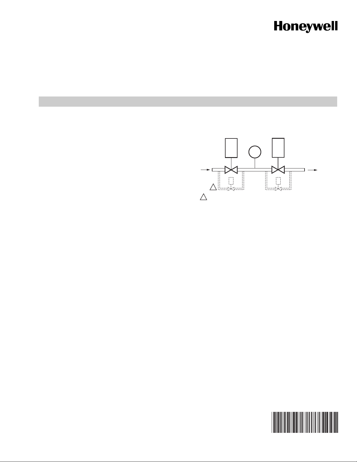
At commissioning time, the Valve Proving System may be
scheduled to occur at one of five different times:
• Never—Device default as received—Valve proving
does not occur.
• Before—Valve proving before run concurrent with Pre-Purge.
• After—Valve proving occurs after the Run state, before
the device goes to Standby (Concurrent with PostPurge, if selected.)
• Both—Valve proving occurs at both times Before and
After, noted above.
• Split—The main valve 2 (MV2) (high pressure) seat test
is performed at the Before time and the main valve 1
(MV1) (low pressure) seat test is performed during the
After time.
RM7800L/40L, EC7840L
system
The following assumptions apply when using the RM7840G,L,
RM7800L, EC7840L:
MV1
VP
SW.
INLET
1
CAUTION: VALVE ENERGIZING TIMING IS BASED ON HONEYWELL VALVE
1
OPENING TIMES OF 13 SECONDS MAXIMUM.
MV1—Wired to terminal 9. It is located in the most upstream
position of the main gas valve train.
VPS—Valve Proving Switch: Setpoint at 1/2 of Main Valve
inlet pressure.
MV2—Wired to terminal 21. It is the main valve located
closest to the burner.
The PII—Pre-Ignition Interlock (or Proof of Closure Switch) for
terminal 20 can be installed on MV1, MV2, or as a series
connection through both valves.
Appendix B lists many wiring options for single and dual fuel
along with the Valve Proving options.
− FOR VALVES WITH TIMINGS GREATER THAN 13
SECONDS OR THOSE THAT DO NOT OPEN THE ACTIVE
VALVE WITHIN THE ENERGIZED TIME, A BYPASS
SOLENOID VALVE (1/4”, 120 VAC) IS REQUIRED TO
OBTAIN THE PROPER TEST PRESSURES.
− THE BYPASS VALVE WILL BE WIRED IN PARALLEL TO THE
VALVE IT IS BYPASSING (TERMINAL 9 FOR MV1 OR
TERMINAL 21 FOR MV2).
Fig. 1. The valve proving system.
MV2
OUTLET
M24161
SPECIFICATIONS
Electrical Ratings, see Table 3:
Voltage and Frequency:
RM78xx—120 Vac (+10/-15%), 50 or 60 Hz (±10%).
EC78xx—220–240 Vac (+10/-15%), 50 or 60 Hz (±10%).
Power Dissipation: RM7800/RM7840/EC7840L: 10W
maximum in the Run mode.
66-1162-2
RM7800L1087; RM7840G1022,L1075; EC7840L1014 RELAY MODULES WITH VALVE PROVING
Maximum Total Connected Load: 2000 VA.
Fusing: 15A maximum, Type SC or equivalent Fast Blow.
Environmental Ratings:
Ambient Temperature:
Operating: -40°F to +140°F (-40°C to +60°C).
Storage: -40°F to +150°F (-40°C to +66°C).
Humidity: 85% relative humidity continuous, noncondensing.
Vibration: 0.5G environment.
Approvals: RM7800L/40G,L:
Underwriters Laboratories Inc. Listed: File No. MP268,
Guide No. MCCZ.
Canadian Standards Association Certified: LR9S329-3.
Factory Mutual Approved: Report No. J.I.1V9A0.AF.
IRI Acceptable.
Federal Communications Commission, Part 15,
Class B—Emissions.
Approvals: EC7840L:
Factory Mutual Approved: Report No. J.I.1V9A0.AF.
IRI Acceptable.
Federal Communications Commission, Part 15,
Class B—Emissions.
This document provides installation and static checkout
instructions. Other applicable publications are:
Publication
No. Product
63-2278 Q7700 Network Interface Unit Product Data
65-0084 Q7800A,B 22-Terminal Wiring Subbase
Product Data
65-0288 S7800A1142 Keyboard Display Module
Product Data
65-0091 S7810A Data ControlBus™ Module Product
Data
65-0095 S7820 Remote Reset Module Product Data
65-0097 221729C Dust Cover Installation
Instructions
65-0101 S7830 Expanded Annunciator Product Data
65-0102 ZM7850A Combustion System Manager™
Operating Instructions
65-0109 R7824, R7847, R7848, R7849, R7851,
R7861, R7886 Flame Amplifiers for the
7800 SERIES Product Data
65-0131 221818A Extension Cable Assembly
Product Data
65-0229 7800 SERIES Relay Modules Checkout and
Troubleshooting Product Data
65-0092 QS7800A ControlBus™ Module, Standard
65-0227 QS7800B ControlBus™ Module, Multidrop
65-0249 S7810M ModBus Module
INSTALLATION
When Installing this Product...
1. Read these instructions carefully. Failure to follow them
could damage the product or cause a hazardous
condition.
2. Check the ratings given in the instructions and marked
on the product to make sure the product is suitable for
the application.
3. Installer must be a trained, experienced, flame
safeguard service technician.
4. After installation is complete, check out the product
operation as provided in these instructions.
WARNING
Fire or Explosion Hazard.
Can cause property damage, severe injury,
or death.
To prevent possible hazardous burner operation, verify
safety requirements each time a control is installed on
a burner.
WARNING
Electrical Shock Hazard.
Can cause serious injury or death.
Disconnect the power supply before beginning
installation. More than one power supply disconnect
may be required.
IMPORTANT
1. Wiring connections for the relay modules are unique;
therefore, refer to Figs. 3, 4, 6, 7, or Appendix B for
proper subbase wiring.
2. Wiring must comply with all applicable codes,
ordinances and regulations.
3. Wiring must comply with NEC Class 1 (Line Voltage)
wiring.
4. Loads connected to the RM7800L/40L, EC7840L must
not exceed those listed on the RM7800L/40L,
EC7840L label or the Specifications, see Table 3.
5. Limits and interlocks must be rated to simultaneously
carry and break current to the ignition transformer,
pilot valve, and main fuel valve(s).
6. All external timers must be listed or component
recognized by authorities who have jurisdiction for
the specific purpose for which they are used.
7. For on-off gas-fired systems, some authorities who
have jurisdiction prohibit the wiring of any limit or
operating contacts in series between the flame
safeguard control and the main fuel valve(s).
8. Two Flame Detectors can be connected in parallel with
the exception of Infrared Flame Detectors (C7015,
C7915), Ultraviolet (C7927, C7961), or Visible
(C7962).
9. This equipment generates, uses and can radiate
radio frequency energy and, if not installed and used
in accordance with the instructions, may cause
interference to radio communications. It has been
tested and found to comply with the limits for a
Class B computing device of Part 15 of FCC rules
which are designed to provide reasonable protection
against such interference when operated in a
commercial environment. Operation of this
equipment in a residential area may cause
interference; in which case, the users at their own
expense may be required to take whatever
measures are required to correct this interference.
10.This digital apparatus does not exceed the Class B
limits for radio noise for digital apparatus set out in
the Radio Interference Regulations of the Canadian
Department of Communications.
66-1162—2 2

RM7800L1087; RM7840G1022,L1075; EC7840L1014 RELAY MODULES WITH VALVE PROVING
Location
Humidity
Install the relay module where the relative humidity never
reaches the saturation point. The relay module is designed to
operate in a maximum 85 percent relative humidity
continuous, noncondensing, moisture environment.
Condensing moisture may cause a safety shutdown.
Vibration
Do not install the relay module where it could be subjected to
vibration in excess of 0.5G continuous maximum vibration.
Weather
The relay module is not designed to be weather tight.
When installed outdoors, protect the relay module using an
approved weather-tight enclosure.
Mounting Wiring Subbase
1.
Mount the subbase in any position except horizontally
with the bifurcated contacts pointing down. The standard
vertical position is recommended. Any other position
decreases the maximum ambient temperature rating.
2.
Select a location on a wall, burner or electrical panel. The
Q7800 can be mounted directly in the control cabinet. Be
sure to allow adequate clearance for servicing,
installation, access or removal of the
EC7840L
Module, flame amplifier, flame amplifier signal voltage
probes, Run/Test Switch, electrical signal voltage probes
and electrical field connections.
3. For surface mounting, use the back of the subbase as a
template to mark the four screw locations. Drill the pilot
holes.
4. Securely mount the subbase using four no. 6 screws.
, Expanded Annunciator, Keyboard Display
RM7800L/40L,
Wiring Subbase
WARNING
Electrical Shock Hazard.
Can cause serious injury, death or equipment
damage.
Disconnect the power supply before beginning
installation to prevent electrical shock, equipment
and control damage. More than one power supply
disconnect may be required.
1. For proper subbase wiring, refer to Figs. 3, 4, 6, 7, or
Appendix B.
2. For proper remote wiring of the Keyboard Display
Module, through a 203541 5-wire Connector, refer to
the Specifications for the Keyboard Display Module
(65-0288), Network Interface Unit (63-2278), Data
ControlBus Module™ (65-0091) or Extension Cable
Assembly (65-0131).
3. Disconnect the power supply from the main disconnect
before beginning installation to prevent electrical shock
and equipment damage. More than one disconnect may
be required.
4. All wiring must comply with all applicable electrical
codes, ordinances and regulations. Wiring, where
required, must comply with NEC, Class 1 (Line Voltage)
wiring.
5. Recommended wire size and type: see Table 1.
6. Recommended grounding practices: see Table 2.
The Keyboard Display Module, Data ControlBus Module™
(for remote mounting or communications), through a 203541
5-wire Connector, or Communication Interface ControlBus
Module must be wired in a daisy chain configuration,
(1(a)-1(a), 2(b)-2(b), 3(c)-3(c)). The order of interconnection of
all the devices listed above is not important. Be aware that
modules on the closest and farthest end of the daisy chain
configuration string require a 120 ohm (1/4 watt minimum)
resistor termination across terminals 1 and 2 of the electrical
connectors, for connections over 100 feet.
7. Recommended wire routing of leadwires:
a. Do not run high voltage ignition transformer wires in
the same conduit with the flame detector, Data
Controlbus Module™, or Remote Reset Module
wiring.
b. Do not route flame detector, Data Controlbus
Module™, or Remote Reset Module leadwires in
conduit with line voltage circuits.
c. Enclose flame detector leadwires without armor
cable in metal cable or conduit.
d. Follow directions in flame detector, Data Controlbus
Module™, or Remote Reset Module Instructions.
8. Keyboard Display Module (KDM): Because the KDM is
powered from a low voltage, energy limited source, it
can be mounted outside of a control panel if it is
protected from mechanical damage.
NOTE: A 13 Vdc power supply must be used any time more
than one Keyboard Display Module is used.
9. Maximum wire lengths follow:
a. RM7800L/40L, EC7840L leadwires—The maximum
length of leadwire is 300 feet to terminal inputs (Control, Pre-Ignition Interlock, Running/Lockout Interlock, High Fire Switch and Low Fire Switch).
b. Flame Detector leadwires—The maximum flame
sensor leadwire length is limited by the flame signal
strength.
c. Remote Reset leadwires—The maximum length of
wire is 1000 feet to a Remote Reset pushbutton.
d. Data Controlbus Module™—The maximum Data
Controlbus Module™ cable length depends on the
number of system modules connected, the noise
conditions and the cable used. The maximum length
of all Data Controlbus Module™ interconnecting
wire is 1000 feet.
10. Make sure loads do not exceed the terminal ratings.
Refer to the label on the RM7800/RM7840/EC7840L or
to the ratings in Tables 3, 4 and 5.
Final Wiring Check
1. Check the power supply circuit. The voltage and frequency tolerance must match those of the
RM7800L/40L, EC7840L. A separate power supply circuit may be required for the RM7800/RM7840/
EC7840L. Add the required disconnect means and
overload protection.
2. Check all wiring circuits and complete the Static
Checkout, see Table 9, before installing the
RM7800L/40L, EC7840L on the subbase.
3. Install all electrical connectors.
4. Restore power to the panel.
3 66-1162—2
RM7800L1087; RM7840G1022,L1075; EC7840L1014 RELAY MODULES WITH VALVE PROVING
2
L1 (HOT) L2
DEMAND
6
17
16
20
F
G
INTERNAL
ELECTRONICS
DEMAND (VALVE
PROVING)
7
1K
PLUG IN FLAME
AMPLIFIER
3K
6K
4K
2K
2K
5K
7K
HIGH FIRE
COMMON
MODULATE
LOW FIRE
L2
3
5
LOW FIRE
SWITCH
HIGH FIRE
SWITCH
8
9
10
21
22
12
13
15
14
ALARM
BLOWER
18
19
PILOT
VALV E
MAIN
VALV E 1
IGNITION
1
DETECTOR
SHUTTER
M24162
4
LIMITS
VALVE PROVING SWITCH
PRE-IGNITION INTERLOCK
FLAME
DETECTOR
1
2
CONTROLLER
AIR FLOW
SWITCH
INTERNAL RELAY OPTO FEEDBACK
FIELD WIRING
INTERNAL WIRING
15 SECOND INTERRUPTED OR MV2 IF VALVE PROVING DEMAND (T17) USED.
RM7800L/RM7840L 120 VAC 50/60 HZ
EC7840L 220-240 VAC 50/60 HZ
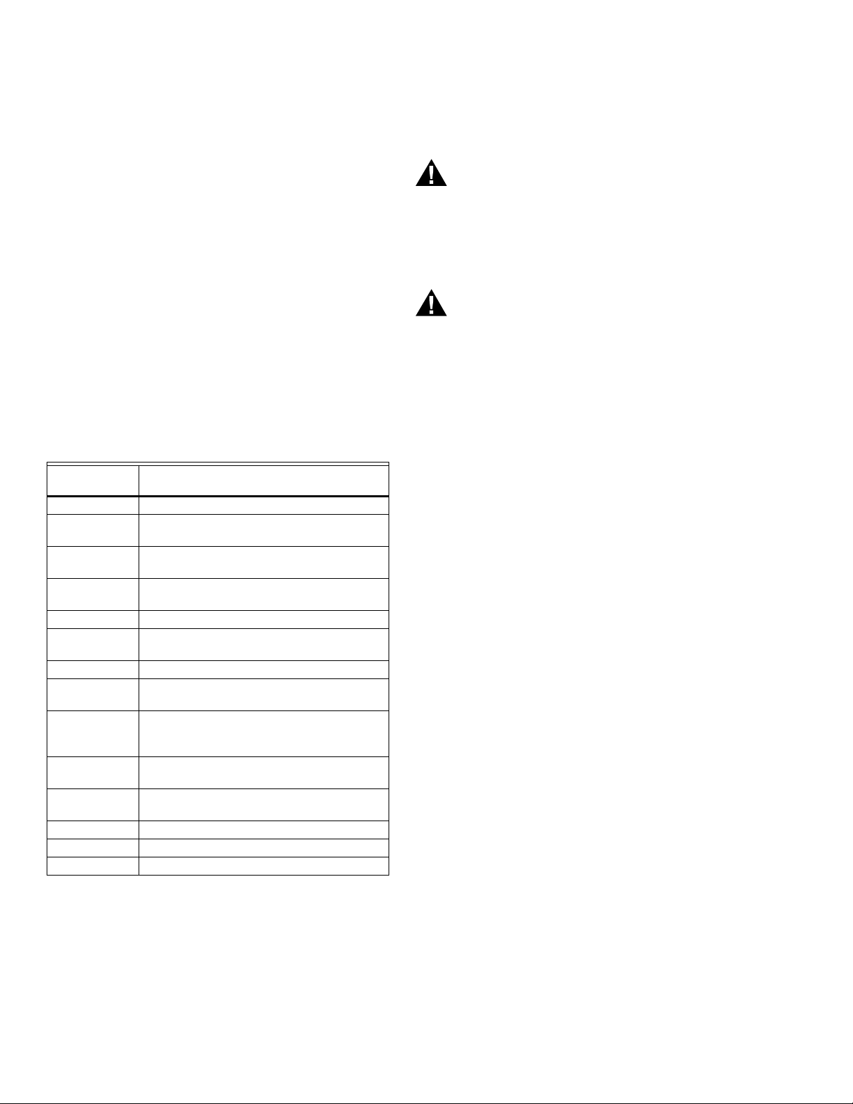
Fig. 2. Internal block diagram of the RM7800L/40L, EC7840L (See Figs. 3, 4, 6 or 7 for individual detailed wiring
instructions).
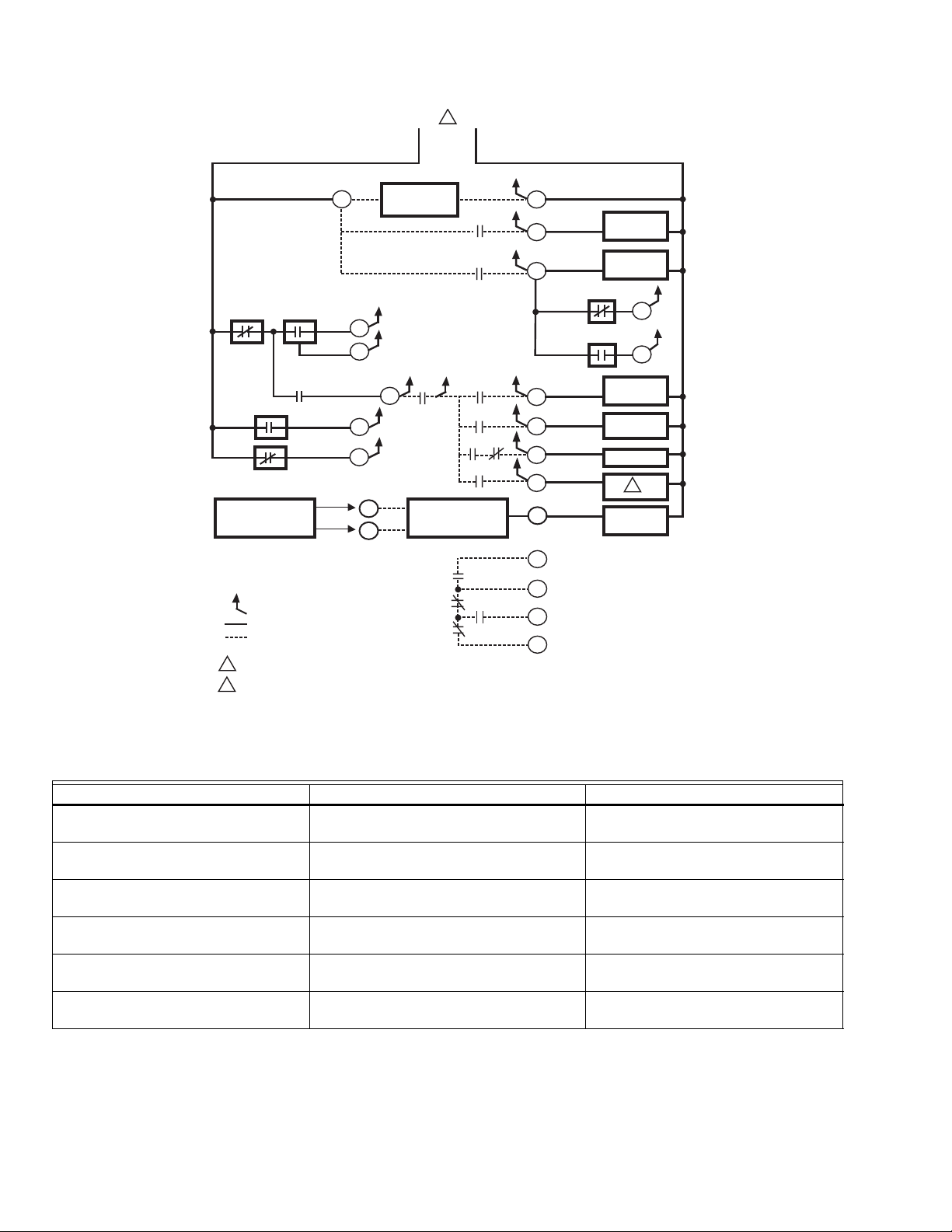
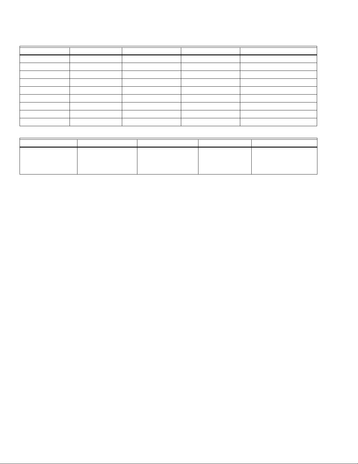
Table 1. Recommended Wire Sizes and Part Numbers.
Application Recommended Wire Size Recommended Part Number(s)
Line voltage terminals 14, 16 or 18 AWG copper conductor, 600
volt insulation, moisture-resistant wire.
Keyboard Display Module (KDM) 22 AWG two-wire twisted pair with ground,
or five wire.
Data ControlBus Module™ 22 AWG two-wire twisted pair with ground,
or five wire.
Remote Reset Module 22 AWG two-wire twisted pair, insulated for
low voltage.
Communications Interface ControlBus™
22 AWG two-wire twisted pair with ground. Belden 8723 shielded cable or
Module
13 Vdc full-wave rectified transformer
power input.
66-1162—2 4
18 AWG wire insulated for voltages and
temperatures for given application.
TTW60C, THW75C, THHN90C.
Belden 8723 shielded cable or
equivalent.
Belden 8723 shielded cable or
equivalent.
—
equivalent.
TTW60C, THW75C, THHN90C.
RM7800L1087; RM7840G1022,L1075; EC7840L1014 RELAY MODULES WITH VALVE PROVING
Table 2. Recommended Grounding Practices.
Ground Type Recommended Practice
Earth ground (subbase and relay
module).
1. Use to provide a connection between the subbase and the control panel of the
equipment. Earth ground must be capable of conducting enough current to blow the
15A fuse (or breaker) in the event of an internal short circuit.
2. Use wide straps or brackets to provide minimum length, maximum surface area
ground conductors. If a leadwire must be used, use 14 AWG copper wire.
3. Make sure that mechanically tightened joints along the ground path are free of
nonconductive coatings and protected against corrosion on mating surfaces.
Signal ground (KDM, Data ControlBus
Module™, Communications Interface
Use the shield of the signal wire to ground the device to the signal ground terminals
[3(c)] of each device. Connect the shield at both ends of the chain to earth ground.
ControlBus™ Module).
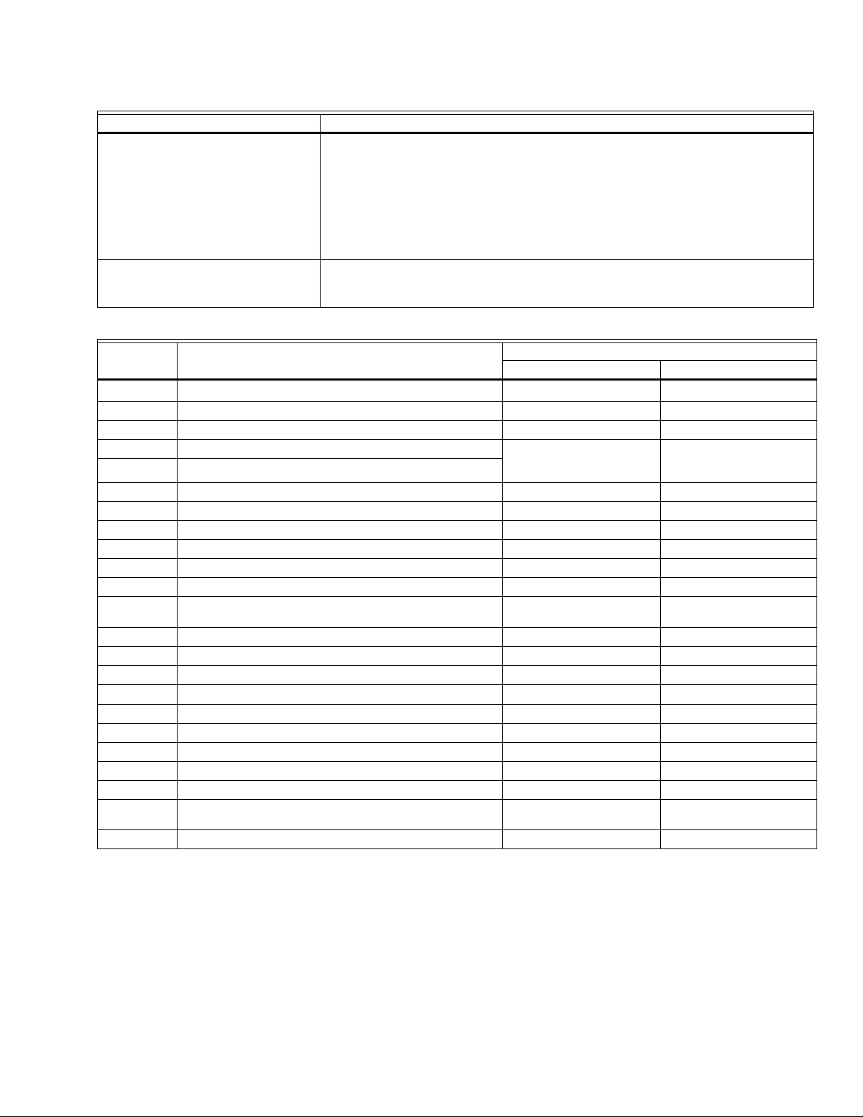
Table 3. Terminal Ratings.
Ratings
Terminal No. Description
G
Flame Sensor Ground
a
120 Vac 220/230/240 Vac
——
Earth G Earth Ground — —
L2(N) Line Voltage Common — —
3 Alarm 1A pilot duty
4
Line Voltage Supply (L1)
b
120 Vac (+10%/-15%),
50 or 60 Hz (±10%)
220-240 Vac (+10%/-15%),
50 or 60 Hz (±10%)
5 Burner Motor 9.8 AFL, 58.8 ALR (inrush) 4A at PF = 0.5, 20A Inrush
6 Burner Controller and Limits Demand (NOT Valve Proving) 1 mA 1 mA
7 Lockout/Running Interlock 8A run, 43A inrush 8A run, 43A inrush —
8 Pilot Valve/Ignition
9 Main Fuel Valve
10 Ignition
F(11) Flame Sensor 60 to 220 Vac,
current limited
c
c
c
4A at PF = 0.5, 20A Inrush
4A at PF = 0.5, 20A Inrush
2A at PF = 0.2
60 to 220 Vac,
current limited
12 Firing Rate High Fire 75 VA pilot duty 0.5A at PF = 0.5
13 Firing Rate Common 75 VA pilot duty 0.5A at PF = 0.5
14 Firing Rate Low Fire 75 VA pilot duty 0.5A at PF = 0.5
15 Firing Rate Modulate 75 VA pilot duty 0.5A at PF = 0.5
16 Valve Proving Switch 1 mA 1 mA
17 Demand — Valve Proving 1 mA 1 mA
18 Low Fire Switch Input 1 mA 1 mA
19 High Fire Switch Input (7800/40L only) 1 mA 1 mA
20 Pre-Ignition Interlock Input 1 mA 1 mA
21 Interrupted/Intermittent Pilot Valve/First Stage Oil Valve
c
4A at PF = 0.5, 20A Inrush
or MV2
22 Shutter 0.5A
a
The relay module must have an earth ground providing a connection between the subbase and the control panel or the
d
equipment. The earth ground wire must be capable of conducting the current to blow the 15A fuse (or breaker) in event of an
internal short circuit. The relay module requires a low impedance ground connection to the equipment frame, which, in turn,
requires a low impedance connection to earth ground.
b
2000 VA maximum connected load to relay module assembly.
c
See Tables 4 and 5.
d
220/240 Vac to 120 Vac, 10 VA (minimum) stepdown transformer (not provided) must be used to drive the shutter.
5 66-1162—2
RM7800L1087; RM7840G1022,L1075; EC7840L1014 RELAY MODULES WITH VALVE PROVING
Table 4. Combinations for Terminals 8, 9, 10 and 21.
Combination No. Pilot Fuel 8 Main 9 Ignition 10 Valve 21
1 C F No Load No Load
2 B F No Load No Load
3 No Load F No Load B
4 F F A No Load
5 No Load F A F
6 D F A No Load
7 No Load D A D
8 D D A No Load
9 No Load D A D
Table 5. Explanation of Each Combination.
AB CD F
4.5A ignition.
50 VA Pilot Duty
4.5A ignition.
a
Pilot Duty refers to solenoid-type valves.
a
plus
180 VA ignition plus
motor valve with:
660 VA inrush, 360 VA
open, 260 VA hold.
2A Pilot Duty.
a
64 VA Pilot Dutya plus
motor valves with:
3850 VA inrush, 700 VA
open, 250 VA hold.
Mounting RM7800L/40L, EC7840L Relay Module (Fig. 9)
1. Mount the RM7800L/40L, EC7840L vertically on the
Q7800 Subbase, or mount horizontally with the
knifeblade terminals pointing downward. When
mounted on the Q7800A, the RM7800L/40L, EC7840L
must be in an electrical enclosure.
2. When mounting in an electrical enclosure, provide
adequate clearance for servicing, installation and
removal of the RM7800L/40L, EC7840L, Keyboard
Display Module, flame amplifier, flame amplifier signal
voltage probes, electrical signal voltage probes, and
electrical connections.
a. Allow an additional two inches below the
RM7800L/40L, EC7840L for the flame amplifier
mounting.
b. Allow an optional three-inch minimum to both sides
of the RM7800L/40L, EC7840L for electrical signal
voltage probes.
3. Make sure no subbase wiring is projecting beyond the
terminal blocks. Tuck in wiring against the back of the
subbase so it does not interfere with the knifeblade
terminals or bifurcated contacts.
IMPORTANT
The RM7800L/40L, EC7840L must be installed with
a plug-in motion rather than a hinge action.
4. Mount the RM7800L/40L, EC7840L by aligning the four
L-shaped corner guides and knifeblade terminals with
the bifurcated contacts on the wiring subbase and
securely tighten the two screws without deforming the
plastic.
66-1162—2 6
120V ALARM
A
BURNER MOTOR
(BLOWER)
RM7800L1087; RM7840G1022,L1075; EC7840L1014 RELAY MODULES WITH VALVE PROVING
SERIES 90
L2
G
3
4
5
Q7800
(L1)
12
13
14
15
16
HIGH FIRE
COMMON
LOW FIRE
MODULATE
FIRING RATE
MOTOR
B
R
W
SERIES 90
CONTROLLER
B
R
W
FOR DIRECT SPARK IGNITION (OIL
OR GAS)
IGNITION
10
TRANSFORMER
8
2ND STAGE
9
FUEL VALVE
(OPTIONAL)
L2
BURNER
CONTROLLER/LIMITS
LOCKOUT INTERLOCKS
(INC. AIR FLOW SWITCH)
10 SEC. INTERRUPTED
PILOT/IGNITION
MAIN FUEL VALVE(S)
5 SECOND IGNITION
(EARLY SPARK
TERMINATION)
FLAME DETECTOR
3
10
17
6
7
8
9
F
18
19
20
21
22
2
LOW FIRE
START SWITCH
HIGH FIRE
PURGE SWITCH
PREIGNITION
INTERLOCK
15 SEC.
INTERRUPTED
PILOT VALVE
MASTER
SWITCH
L1
(HOT)
L2
1
120V, 50/60 Hz (EC7840L 220-240 VAC) POWER SUPPLY.
PROVIDE DISCONNECT MEANS AND OVERLOAD
PROTECTION AS REQUIRED.
2
DO NOT WIRE TO ANY UNUSED TERMINALS.
3
SEE FLAME DETECTOR INSTALLATION INSTRUCTIONS
FOR CORRECT WIRING.
1
M23158
RM7800/RM7840L/EC7840L
INITIATE
(INITIAL
POWERUP
ONLY)
POWER
LED
DISPLAY
BURNER
OPERATING
CONTROLS
ND
INTERLOCKS
FLAME
SIGNAL
FIRING
RATE
MOTOR
INTERLOCK. CHECK
STANDBY
POWER
PREIGNITION INTERLOCK CLOSED
PREPURGE
HOLD
00
DRIVE TO
HIGH FIRE
SAFE START CHECK
SWITCHING
00 00 10 25 00 1520
POWER
LIMITS AND BURNER CONTROLLER CLOSED
19TO
5
TIMED
PREPURGE
POWER
PILOT
FLAME
MAIN
LOCKOUT INTERLOCKS CLOSED
HIGH FIRE SW.
13 12
MOTOR ACTION
PREPURGE
HOLD
DRIVE TO
LOW FIRE
POWER
PILOT
FLAME
MAIN
BURNER/BLOWER MOTOR
10
20TO
4
TO
PFEP
10 SEC.
00
(4 SEC. IF
JR1
CLIPPED
POWER
PILOT
FLAME
MAIN
IGN.
5 SEC.
10 SEC. IGN./PILOT
15 SEC. PILOT
LOW FIRE SW.
MFEP
POWER
PILOT
FLAME
MAIN
ALARMALARMALARMALARM
8
21
MAIN VALVE
TO
L1
6
18
5
TO
FLAME PROVING
13 14
TO
RUN
POWER
PILOT
FLAME
MAIN
ALARM
5
6
7TO
13 15
TO
POSTPURGE
9
POWER
TO
13 14
STANDBY
POWER
IC
PII
SSC
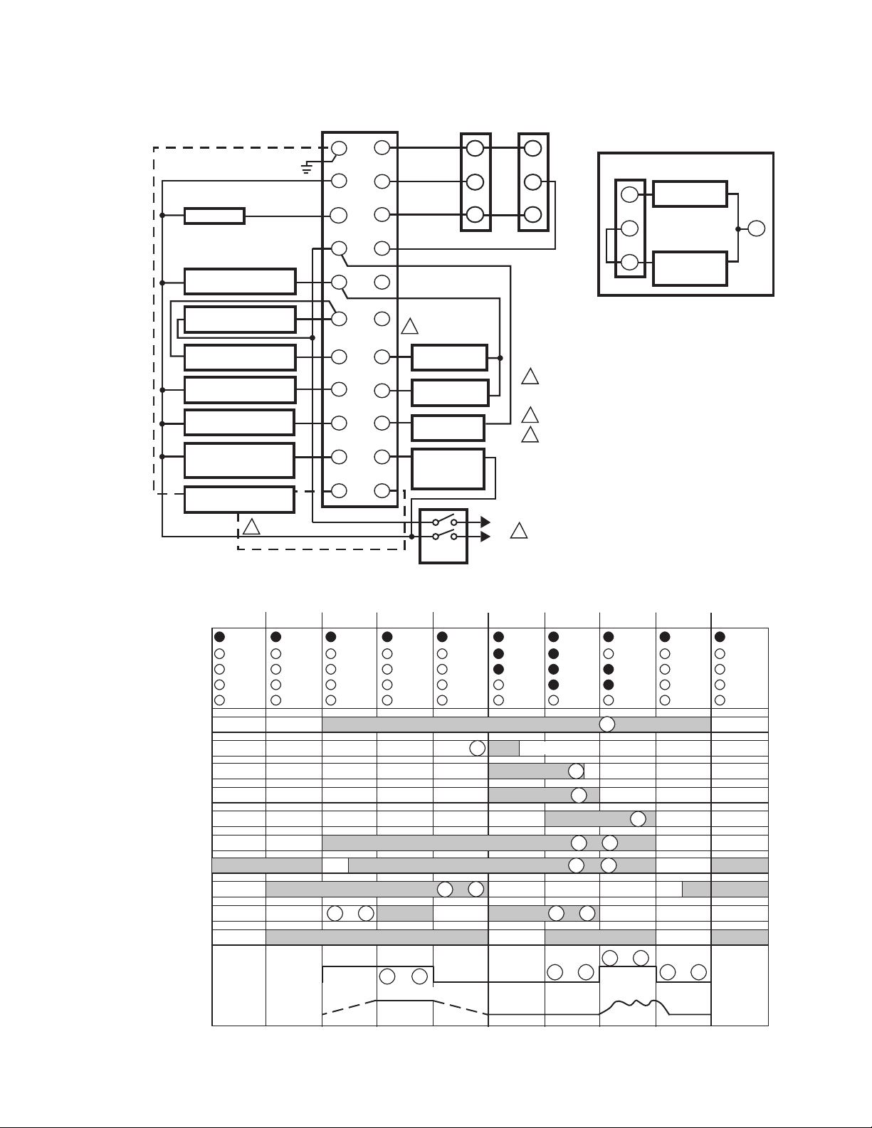
NOTE: SEE APPENDIX FOR APPLICATION OPTIONS.
M24091
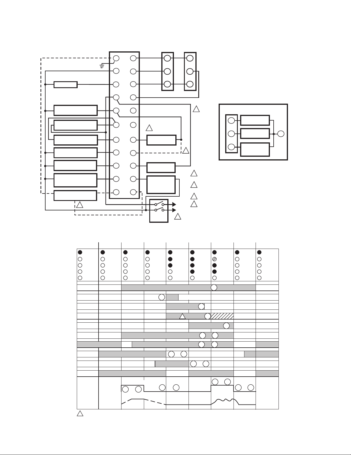
Fig. 3. Typical wiring subbase and sequence for RM7800L/40L, EC7840L without enabled Valve Proving.
7 66-1162—2
RM7800L1087; RM7840G1022,L1075; EC7840L1014 RELAY MODULES WITH VALVE PROVING
A
SERIES 90
120V ALARM
BURNER MOTOR
(BLOWER)
LIMITS
BURNER CONTROL
LOCKOUT INTERLOCKS
(INC. AIR FLOW SWITCH)
10 SEC. INTERRUPTED
PILOT/IGNITION
MAIN FUEL VALVE 1
5 SECOND IGNITION
(EARLY SPARK
TERMINATION)
FLAME DETECTOR
3
L2
10
G
3
4
5
6
7
8
9
F
Q7800
(L1)
12
13
14
15
16
17
18
19
20
21
22
HIGH FIRE
COMMON
LOW FIRE
MODULATE
VALVE PROVING
SWITCH
2
LOW FIRE
START SWITCH
HIGH FIRE
PURGE SWITCH
PREIGNITION
INTERLOCK
MV2 VALVE
MASTER
SWITCH
FIRING RATE
MOTOR
B
R
W
SERIES 90
CONTROLLER
L1
(HOT)
L2
B
R
W
1
120V, 50/60 Hz (EC7840L 220-240 VAC) POWER SUPPLY.
PROVIDE DISCONNECT MEANS AND OVERLOAD
PROTECTION AS REQUIRED.
2
DO NOT WIRE TO ANY UNUSED TERMINALS.
3
SEE FLAME DETECTOR INSTALLATION INSTRUCTIONS
FOR CORRECT WIRING.
4
JR2 INTACT ON RM7800L/40L FOR DSI FUNCTION.
1
FOR DIRECT SPARK IGNITION (OIL
OR GAS)
IGNITION
10
TRANSFORMER
MAIN VALVE 1
9
MAIN VALVE 2
21
17
BURNER
CONTROLLER
L2
M24092
RM7800/RM7840L/EC7840L
INITIATE
(INITIAL
POWERUP
ONLY)
POWER
LED
DISPLAY
BURNER
OPERATING
CONTROLS
ND
INTERLOCKS
FLAME
SIGNAL
FIRING
RATE
MOTOR
INTERLOCK. CHECK
STANDBY
PREIGNITION INTERLOCK CLOSED
PREPURGE
HOLD
00
DRIVE TO
HIGH FIRE
POWER
SAFE START CHECK FLAME PROVING
SWITCHING
00 00 10 25 00 1520
TIMED
PREPURGE
POWER
5
POWER
PILOT
FLAME
MAIN
LIMITS AND BURNER CONTROLLER CLOSED
LOCKOUT INTERLOCKS CLOSED
HIGH FIRE SW.
19TO
13 12
MOTOR ACTION
PREPURGE
HOLD
DRIVE TO
LOW FIRE
BURNER/BLOWER MOTOR
TO
POWER
PILOT
FLAME
MAIN
4
00
10
20TO
PFEP
10 SEC.
(4 SEC. IF
JR1
CLIPPED
POWER
PILOT
FLAME
MAIN
IGN.
5 SEC.
10 SEC. IGN./PILOT
LOW FIRE SW.
5
13 14
MFEP
POWER
PILOT
FLAME
MAIN
ALARMALARMALARMALARM
8
21
MV2
MAIN VALVE
TO
L1
18
TO
TO
RUN
POWER
PILOT
FLAME
MAIN
ALARM
5
2
6
7
13 15
TO
POSTPURGE
1
9
POWER
TO
13 14
STANDBY
POWER
IC
PII
SSC
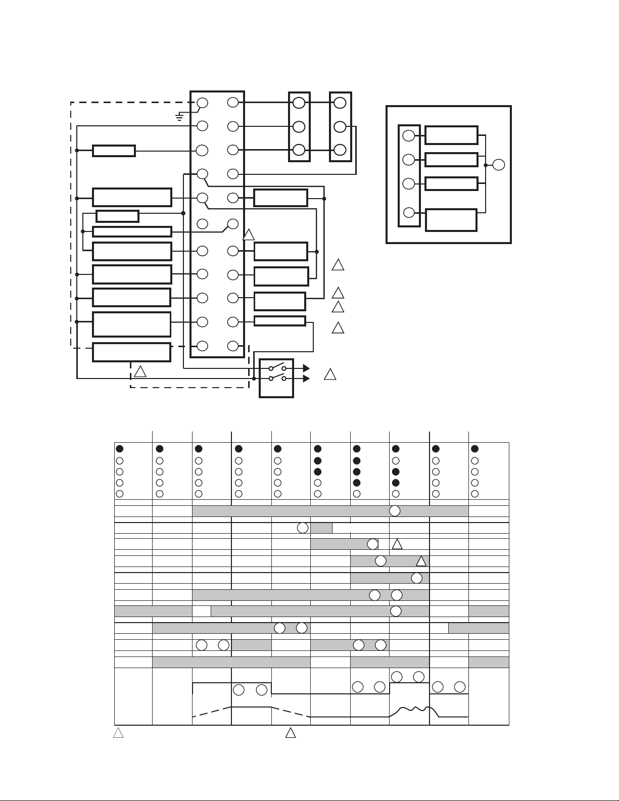
1
MV2 IS MAIN VALVE CLOSEST TO THE BURNER.
Fig. 4. Wiring subbase and sequence for RM7800L/40L, EC7840L with Valve Proving feature enabled.
66-1162—2 8
JR2 REMOVED FOR PILOT SEQUENCE.
2
M24093
RM7800L1087; RM7840G1022,L1075; EC7840L1014 RELAY MODULES WITH VALVE PROVING
BEFORE
HF T19
5
CLOSED
4 SEC.
CONTROLLER
AIRFLOW
CONTROLLER
CONTROLLER
LOCKOUT INTERLOCKS
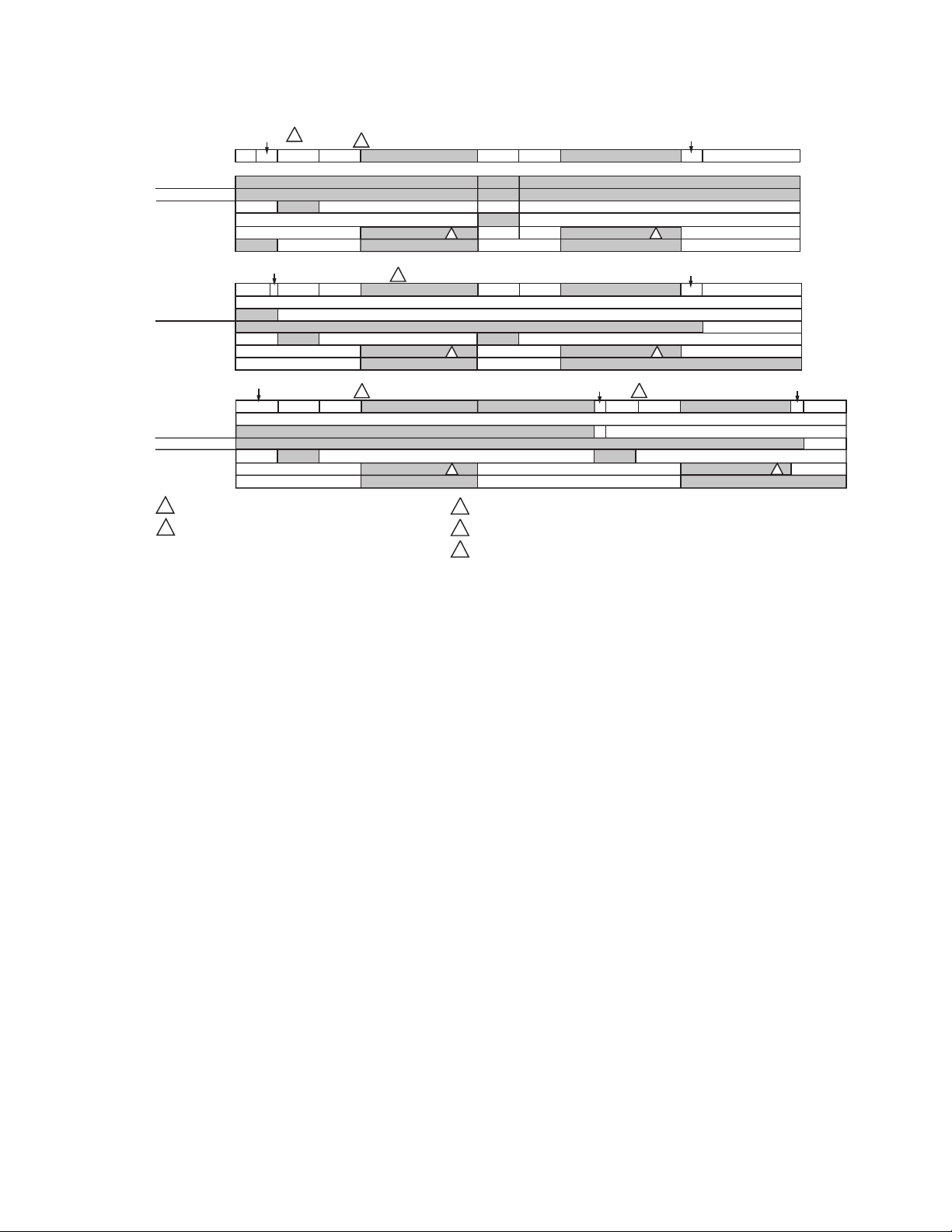
LOCKOUT IF ON, MV1 LEAKING (LOW PRESSURE TEST).
1
LOCKOUT IF OFF, MV2 LEAKING (HIGH PRESSURE TEST).
2
L1-17
17-7
PII (20)
AFTER
RUN
L1-17
L1-7
HF T19
CLOSED
SPLIT
L1-17
L1-7
MV2 (21)
POST
PURGE
4 SEC.
MV2 (21)
4 SEC. 4 SEC.
MV1 (9)
3
3 SEC.
3 SEC.
3
3 SEC.
TEST TIME
VPS (16)
PII (20)
4
TEST TIME
VPS (16)
PII (20)
TEST TIME
VPS (16)
PII (20)
FINISH
PURGE
4 SEC.
3 SEC.
MV1 (9)
1
3 SEC.
4 SEC.
MV1 (9)
1
BURNER RUN TIME
2
TEST IS RUN CONCURRENT WITH PRE PURGE TIME.
3
TEST IS RUN CONCURRENT WITH POSTPURGE, IF POSTPURGE TIME IS ENABLED.
4
5
RM7800/40L/EC7840L ONLY.
TEST TIME
VPS (16)
PII (20)
TEST TIME
VPS (16)
PII (20)
POST PURGE
MV2 (21)
4
2
2
3 SEC.
IGNITION TRIALS
FINISH POST
PURGE
TEST TIME
STANDBY
VPS (16)
PII (20)
FINISH POST
PURGE
1
STANDBY
M24094A
Fig. 5. RM7800L/40G,L and EC7840L Relay Module operation, Valve Proving test options.
9 66-1162—2
RM7800L1087; RM7840G1022,L1075; EC7840L1014 RELAY MODULES WITH VALVE PROVING
SERIES 90
G
Q7800
12
HIGH FIRE
FIRING RATE
MOTOR
B
SERIES 90
CONTROLLER
B
120V ALARM
BURNER MOTOR
(BLOWER)
BURNER
CONTROLLER/LIMITS
RUNNING INTERLOCKS
(INC. AIR FLOW SWITCH)
10 SEC. INTERRUPTED
PILOT/IGNITION
MAIN FUEL VALVE(S)
5 SECOND IGNITION
(EARLY SPARK
TERMINATION)
FLAME DETECTOR
4
INITIATE
(INITIAL
POWERUP
ONLY)
POWER
LED
DISPLAY
BURNER
OPERATING
CONTROLS
AND
INTERLOCKS
FLAME
SIGNAL
FIRING
RATE
MOTOR
INTERLOCK. CHECK
COMMON
13
LOW FIRE
14
MODULATE
15
16
17
4
18
19
20
21
22
POWER
PILOT
FLAME
MAIN
LOW FIRE
START SWITCH
JUMPER WIRE FOR 30s MFEP
PREIGNITION
INTERLOCK
15 OR 30 SEC.
INTERRUPTED/
INTERMITTENT
PILOT VALVE
PREPURGE
HOLD
DRIVE TO
LOW FIRE
POWER
PILOT
FLAME
MAIN
STANDBY
POWER
L2
3
4
(L1)
5
6
7
8
9
10
F
00 00 10 25 00 1520
TIMED
PREPURGE
BURNER/BLOWER MOTOR
LIMITS AND BURNER CONTROLLER CLOSED
RUNNING INTERLOCKS CLOSED
PREIGNITION INTERLOCK CLOSED
SAFE START CHECK
RM7840G SWITCHING
13 12
TO
MOTOR ACTION
R
W
MASTER
SWITCH
00
10
10 SEC. IGN./PILOT
LOW FIRE SW.
13 14
2
L1
(HOT)
L2
1
RM7840G
PFEP
10 SEC.
(4 SEC. IF
JR1
CLIPPED
POWER
PILOT
FLAME
MAIN
ALARMALARMALARM
IGN.
5 SEC.
1
20TO
4
TO
R
W
3
1
120V, 50/60 Hz POWER SUPPLY. PROVIDE DISCONNECT
MEANS AND OVERLOAD PROTECTION AS REQUIRED.
2
ADD JUMPER FOR 30 SECOND MAIN FLAME
ESTABLISHING PERIOD (MFEP).
3
DO NOT WIRE TO ANY UNUSED TERMINALS.
4
SEE FLAME DETECTOR INSTALLATION INSTRUCTIONS
FOR CORRECT WIRING.
MFEP
POWER
PILOT
FLAME
MAIN
ALARM
FOR DIRECT SPARK IGNITION
(OIL OR GAS)
IGNITION
10
TRANSFORMER
1ST STAGE
21
FUEL VALVE
2ND STAGE
9
FUEL VALVE
(OPTIONAL)
RUN
POSTPURGE
POWER
POWER
PILOT
FLAME
MAIN
ALARM
STANDBY
POWER
5
8
21
MAIN VALVE
TO
L1
6
9
6
7TO
PII
18
5
TO
FLAME PROVING
13 15
TO
TO
13 14
SSC
L2
M12260C
IC
1
15/30 SEC. INTERRUPTED/INTERMITTENT PILOT VALVE
Fig. 6. Typical wiring subbase and sequence for RM7840G without Valve Proving enabled.
66-1162—2 10
M24169B
 Loading...