

Page 1
EchoView User’s Guide
EchoView
Rev. F
P/N: F04-4001-000
User’s Guide
1
January 2019
Page 2

EchoView User’s Guide
Product Registration
Register your product online by visiting:
https://www.honeywellanalytics.com/en/support/product-registration
By registering your product, you can:
• Receive notification of product upgrades or enhancements
• Be alerted to training classes in your area
• Take advantage of special offers and promotions
© 2019 Honeywell International.
2
Page 3

EchoView Host User’s Guide
Contents
1. Standard Contents ................................................................................................................................. 7
2. General Information ............................................................................................................................... 7
2.1. Key Features ................................................................................................................................. 8
3. Physical Description .............................................................................................................................. 9
3.1. LCD Display (Monitoring) ............................................................................................................ 10
3.2. LCD Display (In Alarm) ................................................................................................................ 10
4. Specifications ...................................................................................................................................... 11
5. Operation ............................................................................................................................................. 12
5.1. Enable The FMC2000 Controller’s EchoView Function .............................................................. 12
5.2. Turning The EchoView On .......................................................................................................... 13
5.3. Turning The EchoView Off .......................................................................................................... 14
5.4. Battery Indicator .......................................................................................................................... 15
5.5. Buzzer (Audible Alarm) Off Indicator ........................................................................................... 15
5.6. Wireless Communication Indicator .............................................................................................. 16
6. Deploying The EchoView .................................................................................................................... 16
7. Programming The EchoView ............................................................................................................... 17
7.1. Settings ........................................................................................................................................ 18
7.1.1. Buzzer On/Off ....................................................................................................................... 18
7.1.2. LCD Contrast ........................................................................................................................ 19
7.1.3. Serial Number ....................................................................................................................... 19
7.1.4. Firmware Version .................................................................................................................. 20
7.1.5. Factory Reset ........................................................................................................................ 20
7.1.6. Edit Password ....................................................................................................................... 21
7.1.7. Page Disable (EchoView Host) ............................................................................................. 22
7.1.8. Exit ........................................................................................................................................ 23
7.2. Wireless ....................................................................................................................................... 23
7.2.1. Ping Net ................................................................................................................................ 24
7.2.2. PAN ID Setup ........................................................................................................................ 24
7.2.3. Join Net ................................................................................................................................. 25
7.2.4. Channel Setup ...................................................................................................................... 26
7.2.5. Exit ........................................................................................................................................ 27
8. Viewing Data From Connected Monitors............................................................................................. 27
8.1. Viewing Alarm Data ..................................................................................................................... 28
8.2. One Monitor In Alarm .................................................................................................................. 28
8.3. Multiple Monitors In Alarm ........................................................................................................... 29
8.4. Peak Value Reading For Online Or Offline Monitors .................................................................. 30
8.4.1. Clearing Offline Monitors ...................................................................................................... 30
8.5. Panic Alarm ................................................................................................................................. 31
8.6. Enabling/Disabling The “Panic Button” Function......................................................................... 31
8.7. Using The “Panic” Function ......................................................................................................... 32
8.7.1. Trigger All Relays.................................................................................................................. 33
8.7.2. Trigger A Selected Relay ...................................................................................................... 33
8.7.3. Clear Relays ......................................................................................................................... 33
8.7.4. Alarm Abbreviations .............................................................................................................. 34
8.7.5. Alarm Signal Summary ......................................................................................................... 34
3
Page 4

EchoView User’s Guide
8.8. Offline Monitor(s) ......................................................................................................................... 34
8.9. Backlight ...................................................................................................................................... 34
9. Internal Battery Replacement .............................................................................................................. 35
10. Troubleshooting ................................................................................................................................... 37
11. Year Of Manufacture ........................................................................................................................... 38
12. Appendix A: External Battery Replacement ........................................................................................ 39
12.1. External Battery Usage ............................................................................................................... 40
12.2. External Battery Replacement Process ...................................................................................... 42
13. Appendix B: Installation ....................................................................................................................... 43
13.1. Magnet-Mount Installation ........................................................................................................... 43
13.2. Fixed Installation ......................................................................................................................... 44
13.3. Magnetic Mount Alternative Installation ...................................................................................... 47
4
Page 5
EchoView User’s Guide
2460
WARNINGS
This Manual must be carefully read by all individuals who have or will have the responsibility of using, maintaining,
or servicing this product. The product will perform as designed only if it is used, maintained, and serviced in
accordance with the manufacturer’s instructions. The user should understand how to set the correct parameters and
interpret the obtained results.
For safety reasons, this equipment must be operated and serviced by qualified personnel only. Read and
understand the user manual completely before operating or servicing.
AVERTISSEMENT
Pour des raisons de sécurité, cet équipment doit être utilisé, entretenu et réparé uniquement par un personnel
qualifié. Étudier le manuel d’instructions en entier avant d’utiliser, d’entretenir ou de réparer l’équipement.
Read Before Operating
This manual must be carefully read by all individuals who have or will have the responsibility of using, maintaining,
or servicing this product. The product will perform as designed only if it is used, maintained, and serviced in
accordance with the manufacturer’s instructions. The user should understand how to set the correct parameters and
interpret the obtained results.
CAUTION!
To reduce the risk of electric shock, turn the power off before opening this instrument or performing service. Never operate
the instrument when the instrument is open. Service this product only in an area known to be non-hazardous.
WARNING!
Use only the Lithium battery or external rechargeable battery provided by Honeywell RAE Systems. This instrument
has not been tested in an explosive gas/air atmosphere having an oxygen concentration greater than 21%.
Substitution of components may impair suitability for intrinsic safety. Replace batteries only in non-hazardous
locations.
STATIC HAZARD: Clean only with a damp cloth.
For safety reasons this equipment must be operated and serviced by qualified personnel only. Read and
understand instruction manual completely before operating or servicing. Any rapid up-scale reading followed by a
declining or erratic reading may indicate a gas concentration beyond upper scale limit, which may be hazardous.
Intrinsically Safe Marking
Cl. I, Div. 1, Gr A, B, C, D T4
Ta = -40° C to +50° C
IECEx SIR 18.0066X
Sira 18ATEX2251X
II Ex ia IIC T4 Ga
IM1 Ex ia I Ma
Ui = 3.6V, Ci=78µF, Li/Ri=3.5µH/ohm
WARNING!
Substitution of components may impair suitability for intrinsic safety. Replace batteries only in non-hazardous
locations.
5
Page 6

EchoView User’s Guide
CAUTION!
WARNING!
To prevent ignition of flammable or combustible atmospheres, disconnect power before servicing.
Proper Product Disposal At End Of Life
EU Directive 2012/19/EU: Waste Electrical and Electronic Equipment (WEEE)
This symbol indicates that the product must not be disposed of as general industrial or domestic
waste. This product should be disposed of through suitable WEEE disposal facilities. For more
information about disposal of this product, contact your local authority, distributor, or the
manufacturer.
Wireless Security Warning
Wireless data transmission can extend beyond your walls and can be received by anyone with a compatible
adapter. Without proper protection, data can be compromised. Use the security features of all wireless
equipment in your network.
• Bluetooth communication should always be set to OFF unless the functionality is required.
• If possible, pair devices ONLY when in a physically secure area.
This device complies with Part 15 of the FCC Rules / Industry Canada license-exempt RSS standard(s). Operation is
subject to the following two conditions: (1) this device may not cause harmful interference, and (2) this device must
accept any interference received, including interference that may cause undesired operation.
Le présent appareil est conforme aux CNR d'Industrie Canada applicables aux appareils radio exempts de licence.
L'exploitation est autorisée aux deux conditionssuivantes : (1) l'appareil ne doit pas produire de brouillage, et (2)
l'utilisateur del'appareil doit accepter tout brouillage radioélectrique subi, même si le brouillage estsusceptible d'en
compromettre le fonctionnement.
Changes or modifications not expressly approved by the party responsible for compliance could void the user's
authority to operate the equipment.
This equipment has been tested and found to comply with the limits for a Class B digital device, pursuant to part 15 of
the FCC Rules. These limits are designed to provide reasonable protection against harmful interference in a
residential installation. This equipment generates uses and can radiate radio frequency energy and, if not installed
and used in accordance with the instructions, may cause harmful interference to radio communications. However,
there is no guarantee that interference will not occur in a particular installation. If this equipment does cause harmful
interference to radio or television reception, which can be determined by turning the equipment off and on, the user is
encouraged to try to correct the interference by one or more of the following measures:
• Reorient or relocate the receiving antenna.
• Increase the separation between the equipment and receiver.
• Connect the equipment into an outlet on a circuit different from that to which the receiver is connected.
• Consult the dealer or an experienced radio/TV technician for help.
Under Industry Canada regulations, this radio transmitter may only operate using an antenna of a type and maximum
(or lesser) gain approved for the transmitter by Industry Canada. To reduce potential radio interference to other users,
the antenna type and its gain should be so chosen that the equivalent isotropically radiated power (e.i.r.p.) is not more
than that necessary for successful communication.
Conformément à la réglementation d'Industrie Canada, le présent émetteur radio peutfonctionner avec une antenne
d'un type et d'un gain maximal (ou inférieur) approuvé pour l'émetteur par Industrie Canada. Dans le but de réduire
les risques de brouillage radioélectrique à l'intention des autres utilisateurs, il faut choisir le type d'antenne et son gain
de sorte que la puissance isotrope rayonnée équivalente (p.i.r.e.) ne dépasse pas l'intensité nécessaire à
l'établissement d'une communication satisfaisante.
6
Page 7

EchoView Host User’s Guide
Brazil Radio Specifications
Radio model: RM2400A
Frequency range: 2.400 to 2.4835GHz
Modulation: 802.15.4 DSSS BPSK
RF power(Tx): 20dBm
Data rate: 250kbps
1. Standard Contents
Standard Package includes:
• EchoView
• Antenna
• Swivel Belt Clip
• Maintenance/battery replacement tool
• User’s Guide
2. General Information
The EchoView wirelessly receives the data shown on an FMC2000 controller in a MeshGuard
network and displays them on its screen and delivers audible and visible alerts. The EchoView
contains no sensors. Its built-in radio board operates on a frequency of 2.4GHz and complies with
IEEE 802.15.4 standard. It works with the FMC2000 wireless controller on a flexible, robust
wireless network to provide reliable, low-cost operation. Up to four EchoViews can operate on a
single network. It also works in a ProRAE Guardian network with a PC.
7
Page 8

EchoView User’s Guide
2.1. Key Features
Up to 45 days continuous operation using external battery box
IEEE 802.15.4 Mesh network functionality with 64-bit encryption
Mesh network with auto network forming and configuration
Operating distance: up to 300 m, line of sight
Very low-cost installation − no hardwiring involved
Large area coverage with multi-hop mesh network
Field-replaceable battery
Loud audio alarm, 90dB @ 30cm (12″)
Easy-to-read continuous display of signal strength
Bright red flashing alarm
Highly resistant to RFI interference
IP-65 rated for outdoor use in harsh environments
8
Page 9
EchoView User’s Guide
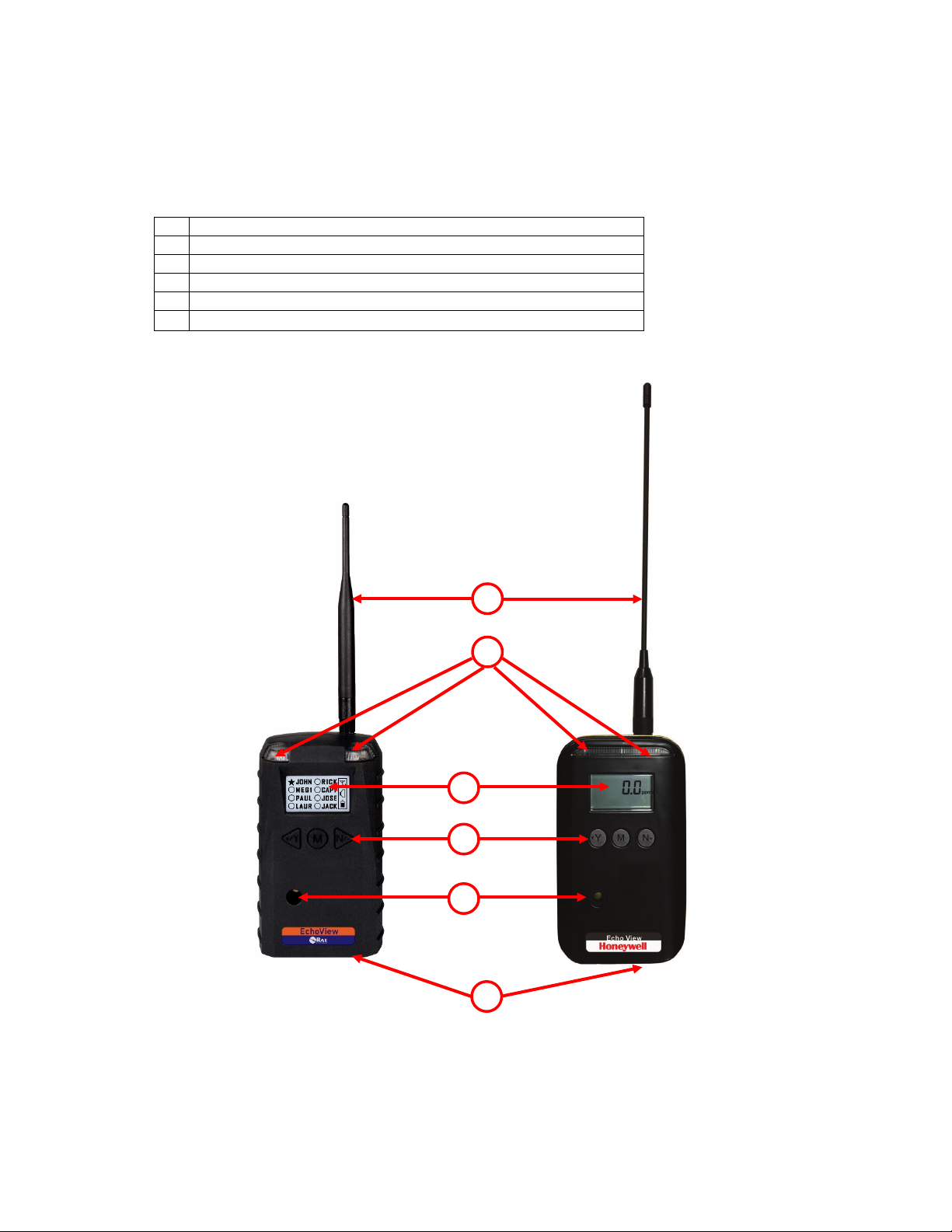
1
LED alarm
2
LCD (with backlighting)
3
Buzzer alarm
4
Battery cover (on bottom)
5
Y/+, MODE, and N/- keys
6
Antenna
6
1
2
3 5 4
Plastic Housing
Metal Housing
3. Physical Description
The EchoView is available in a metal enclosure or a plastic enclosure. Functionality is identical,
regardless of the enclosure.
9
Page 10
EchoView User’s Guide
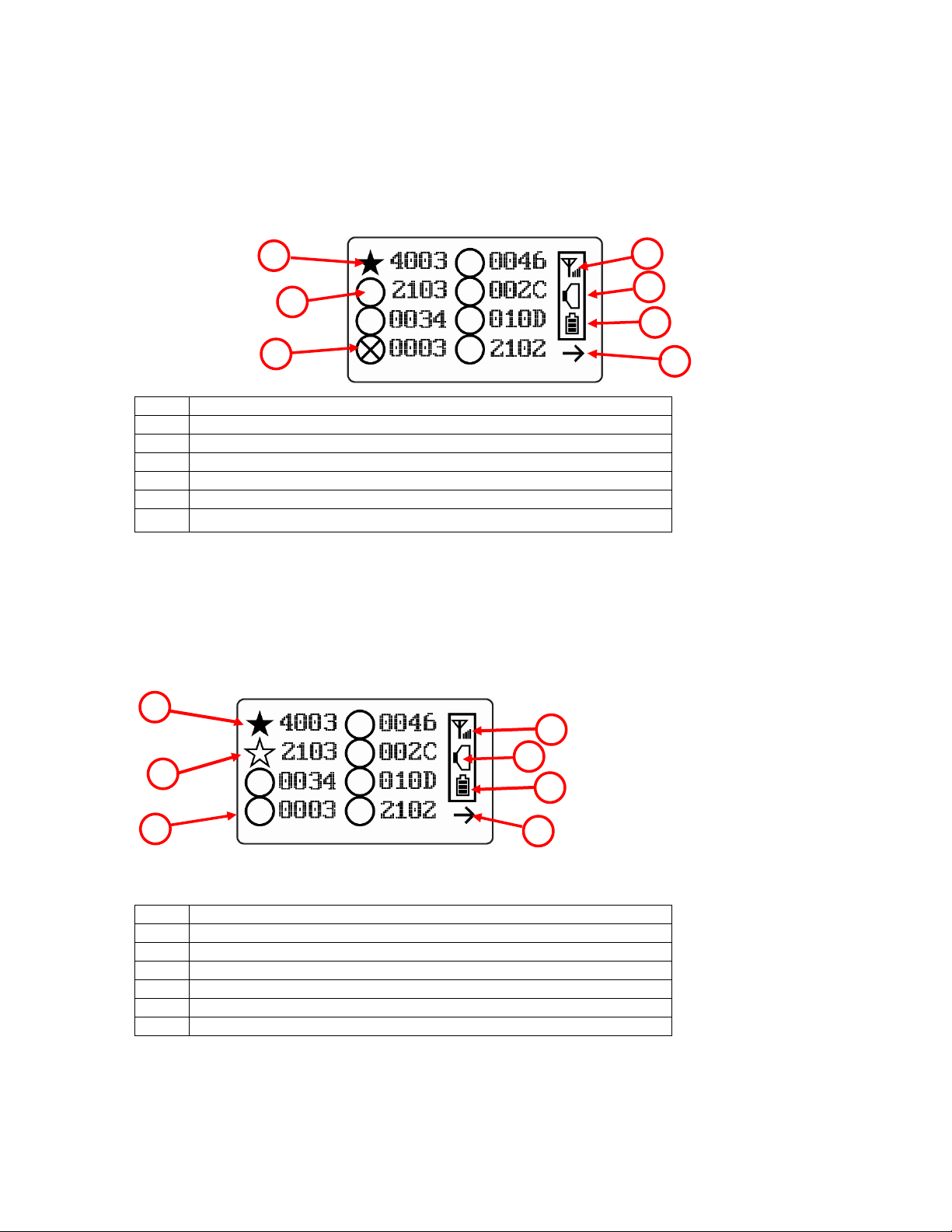
1
Selected monitor (solid circle or star)*
2
Unselected monitor (open circle or star)
3
Offline monitor (open circle with “X”)
4
Radio transmission indicator (“H” is shown for “Host”)
5
Audible alarm on/off indicator (“on” shown)
6
Battery indicator
7
Arrow indicating more than 8 instruments, pointing to next “page”
1
Monitor in alarm and selected (solid star)
2
Unselected monitor in alarm (open star)
3
Unselected monitor not in alarm (open circle)
4
Radio transmission indicator (“H” is shown for “Host”)
5
Audible alarm on/off indicator (“on” shown)
6
Battery indicator
7
Arrow indicating more than 8 instruments, pointing to next “page”
1
2 34
5 6 1 2 34 5
7
7
6
3.1. LCD Display (Monitoring)
LCD Display (Monitoring)
Note: The Unit ID is typically the radio ID, depending on the portable monitor’s setting.
3.2. LCD Display (In Alarm)
10
Page 11

EchoView User’s Guide
RF Certifications
FCC Part15
Type Approval Reg. No.: R-4635
Display
Graphical LCD (1 x 1.5″) with backlight
Audible alarm
90dB @ 30cm
Visual alarm
2 super-bright red LEDs
Calibration
None necessary
EM Immunity
No effect when exposed to 0.43mW/cm2 RF
interference (5-watt transmitter at 12")
Operating Range
Up to 300 meters/1,000 feet to Mesh Router, or
up to 1km/0.6 miles
User Interface
Three keys (Y/+, MODE, N/-)
Power Supply
D-size Lithium replaceable battery, +3.6V
Operation Time
Internal Battery: Up to 10 days
External Battery: Up to 45 days
Operating
Temperature
-4° to 122° F (-20° to +50° C)
Humidity
0% to 95% relative humidity, non-condensing
Dimensions
Metal Enclosure: 15.7cm x 9.3cm x 5.1cm
(10.5″ x 3.7″ x 2.1″)
Weight
Metal Enclosure: 1.2 kg (2.65 lbs)
Plastic Enclosure: 0.6 kg (1.3 lbs)
IP Rating
IP-65
Mounting
Optional stainless-steel bracket with pole
mount or magnetic mount
4. Specifications
CE EN 300328
Wireless Approval For UAE In Middle East
(TRA REGISTERED No: ER36063/14
DEALER No: HONEYWELL INTERNATIONAL
MIDDLE EAST - LTD - DUBAI BR
TRA REGISTERED No: ER36635/15
DEALER No: HONEYWELL INTERNATIONAL
MIDDLE EAST - LTD - DUBAI BR)
Wireless Approval for QATAR In Middle East
ictQATAR Type Approval Reg. No.: R-4465
(6.2” x 3.7” x 2.0”)
Plastic Enclosure: 26.5cm x 9.5cm x 5.5cm
FCC Part 15 Statement
This device complies with Part 15 of the FCC rules. Operation is subject to the following two
conditions: (1) This device may not cause harmful interference, and (2) this device must accept any
interference received, including interference that may cause undesired operation.
11
Page 12

EchoView User’s Guide
5. Operation
The EchoView only operates in RTR (Router) mode. Therefore, when it is turned on, it is always
operational.
Whenever you start EchoView, it tries to rejoin the last network it was part of. Therefore, if the
network is within range and if the channel and Pan ID have not changed, the EchoView should be
able to rejoin the network without action on your part.
Make sure the battery with sufficient charge is installed before operating the EchoView. Refer to
page 35 for information on battery installation and replacement.
5.1. Enable The FMC2000 Controller’s EchoView
Function
The EchoView can only receive data from an FMC2000 Controller if the controller is configured to
broadcast data to it by enabling its EchoView Function. Therefore, you should perform this simple
configuration before adding one or more EchoViews to a network.
To enable the Pager function on the FMC2000 Controller:
1. Press the “MENU” key from Normal Operation Mode to enter the Configuration menu.
2. Provide a 4-digit password (the default value is 1234).
3. Press “Enter.”
4. The “General Settings” icon is highlighted. Press “Enter.”
5. Scroll to “Advanced Settings.”
6. Press “Enter.”
7. Input the advanced (6-digit) password.
8. Press Enter.
9. Input the 6-digit advanced password (the default is 123456).
10. Press Enter.
11. Scroll through the options until “EchoView” is highlighted.
12. Press “Enter.”
13. Select “All Alm” (all alarms) or “SNS Alarm” (sensor alarms, including High, Low, etc.) by using
the up and down arrows. (There is also a “Disable” option that shuts off EchoView functionality.)
14. Press “Enter” to lock in your selection and exit the EchoView Function menu.
The FMC2000 Controller is now broadcasting its data for EchoViews.
12
Page 13

EchoView User’s Guide
5.2. Turning The EchoView On
Hold down the [MODE] key and release it when the EchoView display and LED lights light up. The
display indicates that the unit is now on:
During startup, the display shows the firmware version:
Next, it shows the firmware’s build date and time:
This is followed by the Unit Mode and Modem Type:
Note: Modem type relates to its permanently set operating frequency. For further information, refer
to page 23.
13
Page 14
EchoView User’s Guide
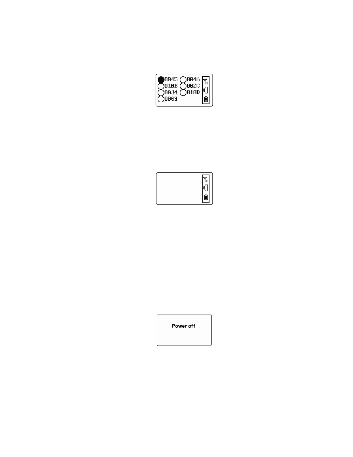
Then the EchoView initializes the wireless network. When the network is found and communication
is established, the main reading screen is shown. It includes signal strength, battery charge, and
the identification numbers of all monitors on the network:
The monitor name shown on the EchoView screen is either the ID of the monitor’s radio.
Important! Each name on a network must be unique. The automatically assigned radio ID is unique by
default.
Note: If no monitors are within the EchoView's range, its display will only show the radio-on indicator,
battery charge, and buzzer on/off icon.
If you see this screen, check the following:
• Is the antenna attached?
• Does the Pan ID match the network you want to join?
• Does the Channel match the channel on which the other instruments are operating?
• Are the other instruments turned on and within range?
• Did you change the Pan ID or Channel? If so, restart the instrument.
• Is the FMC2000 Controller’s Pager Function enabled? If not, enable it.
5.3. Turning The EchoView Off
Hold down the [MODE] key through the “5…4…3… 2… 1… Power Off” sequence. The EchoView is
off when the display is blank. Release the [MODE] key.
The EchoView is now off.
14
Page 15
EchoView User’s Guide
Buzzer on
Buzzer off
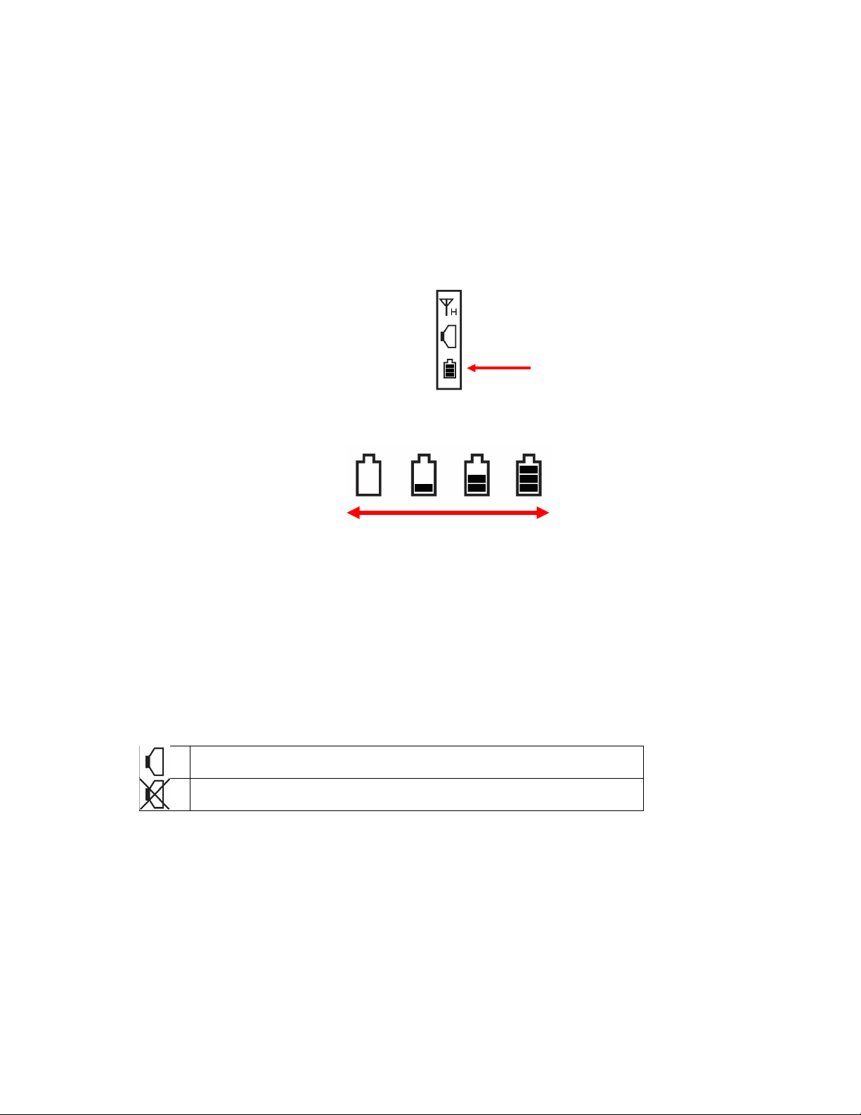
Battery
Empty Full
5.4. Battery Indicator
The EchoView’s internal battery is designed to provide power for up to 10 days. When the battery
gets low, the EchoView beeps once per minute and the battery icon is empty. See page 35 for the
replacement procedure. It is recommended that the battery be changed immediately, to minimize
potential downtime. When the battery is almost completely depleted, the LCD displays “Power off,”
and the LED and buzzer alarms activate once per second. The battery icon also blinks on and off.
The low battery alarm continues until the battery runs out. Then the unit shuts down automatically.
Battery power is indicated with an icon in the lower right corner of the screen, below the wireless
communication indicator and buzzer icon:
Charge
Battery charge is shown from empty to full:
Indicator
Note: For a fixed-system application, an external power source, the RAE PowerPak, can be used
as a substitute for the internal battery. Only remove the external battery adapter in non-hazardous
locations.
5.5. Buzzer (Audible Alarm) Off Indicator
The EchoView’s buzzer (audible alarm) can be turned off, so the LED visible alarms flash but there
is no sound when in alarm. The icon on the main screen indicates its state.
15
Page 16

EchoView User’s Guide
Radio on
5.6. Wireless Communication Indicator
The display employs an antenna icon to show that the radio is on. A letter “H” indicates that the
EchoView is operating in the Host mode. It is located in the upper right corner of the display:
Indicator
Signal strength is represented by vertical bars to the right of the antenna icon. The greater the
number of bars to the right of the antenna icon, the better the connection quality.
Note: An “X” indicates no signal is detected.
6. Deploying The EchoView
When deploying a MeshGuard network that utilizes EchoViews, make sure the rest of the network has
been set up before using an EchoView. The EchoView gets its information about the monitors on a
network from the FMC2000 controller. It does not aggregate network data from all its nodes. Therefore,
make sure the FMC2000 is operational and in communication with all monitors on the network, as well as
with the EchoView.
Before deploying an EchoView, it is important to have the Pan ID and Channel number on which the rest
of the network is operating. Without these numbers to program into your EchoView, you cannot make it
communicate with the network.
16
Page 17

EchoView User’s Guide
7. Programming The EchoView
Programming Mode is accessed by first providing the correct password.
Press and hold [MODE] and [N/-] until you see this screen:
Input the 4-digit password:
• Increase the number from 0 through 9 by pressing [Y/+].
• Decrease the number from 9 through 0 by pressing [N/-].
• Step from digit to digit using [MODE].
Once all the four digits have been entered, press [MODE] again to see the following screen appear.
Press [Y/+] to enter the password.
If you make a mistake, you can cycle through the digits by pressing [MODE] and then using [Y/+]
and [N/-] to change the number in each position.
Note: The default password is 0000.
If your password is incorrect, you see this screen:
After a few seconds, the EchoView exits to its main screen.
When you have successfully entered Programming Mode, you see this screen:
Note: If you do not make a selection in 60 seconds, the EchoView automatically exits to the main
screen.
Press [Y/+] or [N/-] to scroll to “Settings,” “Wireless,” or “Exit.” Then press [MODE] to select your
choice.
17
Page 18

EchoView User’s Guide
Settings provides information about your instrument. Some screens are read-only (you cannot edit them),
but other screens allow you to change settings.
Wireless consists of parameters you can set/change that affect wireless functionality, network
configuration, etc.
7.1. Settings
Settings include some read-only information (Serial Number and Firmware Version) and some settings
that you can change.
Press [Y/+] to scroll up or [N/-] to scroll down.
Note: Two more screens contain additional options:
Note: The scrolling “wraps,” so once you reach the first or last item, it starts scrolling through the
items again.
Eight choices (including Exit) are available:
• Buzzer On/Off
• LCD Contrast
• Serial Number (read-only)
• Firmware Version (read-only)
• Factory Reset
• Edit Password
• Page Disable
• Exit
To make a selection, scroll until the circle to the left of your choice is black, and then press [MODE].
Note: If you do not make a selection in 60 seconds, it automatically exits to the main screen.
7.1.1. Buzzer On/Off
You can turn the buzzer (audible alarm) on or off. To access the parameter, press [MODE] when
its name is highlighted (dark circle):
18
Page 19

EchoView User’s Guide
You are asked whether you want to disable (or enable, if it is already disabled) the audible alarm:
or
To toggle the audible alarm from on to off (or off to on), press [Y/+], and a confirmation message
appears. To exit without performing the reset, press [N/-].
or
7.1.2. LCD Contrast
The display’s contrast is adjustable via this menu. To access it, press [MODE] when its name is
highlighted (dark circle):
The contrast value is shown in the display. Step through the digits from left to right by pressing [MODE].
Change a digit’s value by pressing [Y/+] to increase and [N/-] to decrease. After the third digit, you see a
flashing “?”
• Save your changes by pressing [Y/+].
• Exit without saving changes by pressing [N/-].
• Step back to the first digit by pressing [MODE].
7.1.3. Serial Number
This shows the Serial Number of the EchoView. To view it, press [MODE] when “Serial Number” is
highlighted (dark circle):
19
Page 20

EchoView User’s Guide
The serial number is shown in the display:
Press [MODE] to return to the Settings menu. If you do not make a selection in 60 seconds, the unit
automatically exits to the menu.
7.1.4. Firmware Version
This shows the firmware version incorporated in the instrument. It is read-only. You cannot make
changes to the information. To view it, press [MODE] when its name is highlighted (dark circle):
Press [MODE] to return to the Settings menu. If you do not make a selection in 60 seconds, it
automatically exits to the menu.
7.1.5. Factory Reset
You can perform a factory reset to the instrument’s original settings. To access it, press [MODE]
when its name is highlighted (dark circle):
You are asked whether you want to perform the factory reset:
To perform the reset, press [Y/+]. To exit without performing the reset, press [N/-].
20
Page 21

EchoView User’s Guide
While the EchoView is being reset to its original factory settings, the screen shows that the activity
is taking place:
When the reset is complete, this screen appears:
Then the unit returns to the Settings menu.
Note: Factory Reset changes all EchoView settings to factory-default values. These include:
• PAN ID
• Channel
IMPORTANT!
All custom-configured settings are removed and cannot be retrieved!
7.1.6. Edit Password
You can change the password by selecting “Edit Password.”
At this screen, input your new password over the old one (or the default):
• Increase the number from 0 through 9 by pressing [Y/+].
• Decrease the number from 9 through 0 by pressing [N/-].
• Step from digit to digit using [MODE].
21
Page 22

EchoView User’s Guide
Note: If you make a mistake, you can cycle through the digits by pressing [MODE] and then using
[Y/+] and [N/-] to change the number in each position.
Once all the four digits have been entered, press [MODE] again to see the following screen appear.
• Save your changes by pressing [Y/+].
• Exit without saving changes by pressing [N/-].
• Step back to the first digit by pressing [MODE].
Saving the password takes a moment, and a screen indicates that it has been successfully saved:
7.1.7. Page Disable (EchoView Host)
The Page feature can be enabled to allow up to four additional EchoView Host “mimic panels” to be
used as part of a closed-loop system.
When the Page feature is enabled, the EchoView Host broadcasts instrument data. These data can
be picked up by mimic panels. If no mimic panels are planned to be used, this feature should be
disabled, in order to ensure data privacy. Note: The default value is “Disabled.”
To enable (or later to disable) the feature, press [MODE] to reach this screen (if it is already
enabled, it will say “Page Disable?):
22
Page 23

EchoView User’s Guide
Press [Y/+] to change the setting. After the setting is accepted, this screen is shown (or one that
says “Page Disabled”):
7.1.8. Exit
Scroll until “Exit” is selected.
Press [MODE] to return to the Programming Menu.
Note: If you do not make a selection in 60 seconds, it automatically exits to the menu.
7.2. Wireless
Wireless consists of editable parameters and actions to configure, form, and test a closed-loop
wireless network.
Under Programming Menu, select “Wireless.”
Press [Y/+] to scroll up or [N/-] to scroll down through wireless sub-menus.
Note: When you reach the last item and continue scrolling, a second screen appears:
The scrolling “wraps,” so once you reach the first or last item of either screen, it starts scrolling
through the items in the other screen again.
Five choices (including Exit) are available:
• Ping Net
• PANID Setup
• Form Net
• Channel Setup
• Exit
23
Page 24

EchoView User’s Guide
To make a selection, scroll until the circle to the left of your choice is black, and then press [MODE].
Note: If you do not make a selection in 60 seconds, it automatically exits to the main Programming
Menu.
7.2.1. Ping Net
Pinging tests the radio connection between the EchoView and other units on its network. (A “ping”
is a short signal sent to the network to prompt a reply; it contains no other data.)
Scroll until “Ping Net” is selected.
Press [MODE] to ping the network. This message appears:
Press [Y/+]. The Echoview broadcasts a ping signal to its network. All devices in the network that
receive the ping signal respond with a beep if they are within the range. (The Echoview does not
beep or flash its LED lights.) You can also ping from an instrument in the network. If it is within
range, the EchoView responds with a beep and an LED light flash.
If a network ping is unsuccessful, check the following:
• Is the antenna attached?
• Does the PAN ID match the PAN ID of other instruments in the network?
• Does the Channel match the channel on which the other instruments are operating?
• Are the other instruments turned on and within range?
7.2.2. PAN ID Setup
All units on a network must be programmed with the same PAN ID (Personal Network Identifier) to
ensure communication compatibility.
When you see this screen, press [MODE] to view the current PAN ID or to change it:
Important! The allowed range for PAN ID numbers is 001 through 999.
24
Page 25

EchoView User’s Guide
The screen shows the PAN ID, with the cursor blinking on the first digit. Step through the digits from
left to right by pressing [MODE]. Change a digit’s value by pressing [Y/+] to increase and [N/-] to
decrease. After the third digit, you see a flashing “?”
• Save your changes by pressing [Y/+].
• Exit without saving changes by pressing [N/-].
• Step back to the first digit by pressing [MODE].
Note: If you do not press a key within 60 seconds, the screen reverts to the programming Menu
screen showing Settings, Modem, and Exit.
7.2.3. Join Net
This screen is for joining an existing network. When you see this screen, press [MODE] to form a
network. This function allows the radio to scan all available channels and choose the leastcongested one:
The screen now displays a message asking if you want to confirm your choice to join a network:
• Press [Y/+] to join a network and automatically find the best channel to operate on.
• Press [N/-] to exit without joining a network.
While the instrument starts joining a network, this message appears:
Once the device has selected the least-congested channel and a network is joined, this message is
displayed:
25
Page 26

EchoView User’s Guide
7.2.4. Channel Setup
All units in a network must operate on a single channel. The available channels vary by the internal
wireless modem’s frequency, and channel ranges are set by RAE Systems by Honeywell to
correspond with the wireless modem frequency.
These are the modem frequencies and channel ranges:
2.4 GHz: Channels 11 through 26
Note: You can use “Form Net” to automatically have the EchoView select the least-congested
channel.
Scroll until “Channel Setup” is selected.
Press [MODE] to view or change the channel. The range of available channels is shown in
parentheses. The screen also shows the channel number, with the cursor blinking on the first digit:
Step from digit to digit from left to right by pressing [MODE]. Change a digit’s value by pressing
[Y/+] to increase and [N/-] to decrease. When you press [MODE] you see a flashing “?” after the
second digit:
• Save your changes by pressing [Y/+].
• Exit without saving changes by pressing [N/-].
• Step back to the first digit by pressing [MODE].
If you have saved the channel number successfully, you see this screen:
Important! Remember that the range of allowed channels for instruments on a EchoView’s network
depends on the wireless modem frequency. Therefore, you may not be able to change the channel
26
Page 27

EchoView User’s Guide
Monitor
to a number outside of its assigned set of numbers. If you select an incompatible channel number,
you will see this screen, and then the EchoView returns to the Wireless menu.
7.2.5. Exit
To exit Wireless and return to the main Programming Menu, scroll until “Exit” is shown:
With “Exit” selected, press [MODE]. The EchoView now returns to the Programming Menu screen.
8. Viewing Data From Connected Monitors
You can view the data from each monitor on the network, even if the monitor is not in alarm.
To view the selected monitor’s data, select the monitor you want to view. Scroll up or down the list
by using the [Y/+] and [N/-] keys.
To make your selection, press [MODE]. The screen changes to show the data. For example:
Identifier
Sensor
Location
This provides you with an overview, including
• The monitor’s location (if it has been programmed into the FMC2000 controller)
• The type of monitor
• The type of sensor
• The alarm state (NONE is shown when a monitor is not in alarm)
• The level or concentration of the substance being monitored (the unit depends on the type of
sensor)
To exit from this screen back to the main reading screen, press [MODE].
Alarm type
Sensor
27
Page 28

EchoView User’s Guide
8.1. Viewing Alarm Data
Whenever the FMC2000 controller in a network receives alarm data from a monitor on the network,
the EchoView also receives it. When monitoring the network and when no alarms are present, the
EchoView’s display looks like this:
All monitors are represented with a unique identifier and a circle. (A filled—dark—circle indicates the
selected monitor for viewing, whereas an unfilled circle indicates the monitor’s presence on the network
and no alarm.)
To select a monitor: Press [Y/+] to scroll up or [N/-] to scroll down.
Note: The scrolling “wraps,” so once you reach the top or bottom item, it starts scrolling through the items
again. If there are more monitors than the display can show on one screen, it advances to the next
screen. When the last monitor on that screen is reached, it “wraps” back to the first item on the initial
screen.
To make a selection: Scroll until the circle to the left of your choice is black, and then press [MODE].
Note: If you do not make a selection in 60 seconds, it automatically exits to the main reading screen.
8.2. One Monitor In Alarm
Whenever a monitor on the network goes into alarm the EchoView also receives it and displays it.
When monitoring the network and when no alarms are present, the EchoView’s display looks like
this:
All monitors are represented with a unique identifier and a circle. (A filled—dark—circle indicates
the monitor has been selected for viewing.)
To select a monitor: Press [Y/+] to scroll up or [N/-] to scroll down.
Note: The scrolling “wraps,” so once you reach the top or bottom item, it starts scrolling through the
items again. If there are more monitors than the display can show on one screen, it advances to the
next screen. When the last monitor on that screen is reached, it “wraps” back to the first item on the
initial screen.
To make a selection: Scroll until the circle to the left of your choice is black, and then press
[MODE].
Note: Only one monitor can be selected for viewing at a time.
28
Page 29

EchoView User’s Guide
Monitor
8.3. Multiple Monitors In Alarm
If any other monitors on the network go into alarm while one is already in alarm, the circle
accompanying second monitor in alarm also changes to a star. However, if the monitor is not the
one currently selected, the star is unfilled:
To view a monitor’s data:
Scroll up or down through the list of monitors by pressing the [Y/+] or [N/-] key. As the selection
advances down the list, each subsequent circle or star is filled (black).
Note: Only one monitor can be selected for viewing at a time.
When the icon of the monitor you want to view is highlighted, then you can make your selection.
Press [MODE]. The screen changes to show the data. For example:
Identifier
Sensor
Location
This provides you with an overview of the alarm state, including
• The monitor’s location (if it has been programmed into the FMC2000 controller)
• The type of monitor
• The type of sensor
• The type of alarm state (HIGH alarm, LOW alarm, STEL, alarm, etc.)
• The level or concentration of the substance being monitored (the unit depends on the type of
sensor)
To exit from this screen back to the main reading screen, press [MODE].
Alarm type
Sensor reading
29
Page 30

EchoView User’s Guide
8.4. Peak Value Reading For Online Or Offline Monitors
The peak value reading from monitors on the network can be viewed anytime. Scroll down to the
instrument and select it. If the monitor is currently offline, its last received peak reading is shown.
This value is retained until communication with the monitor is restored.
To view a monitor’s peak reading:
1. Press [Y/+] or [N/-] to scroll through the list of monitors. Then press [MODE] to select the
highlighted monitor.
The monitor’s type and status are shown (A = Alarm, R = Real-time Reading):
2. Press [N/-] to advance through the sensor’s information (L = Low Alarm, H = High Alarm):
3. Hold the [Y/+] key for 3 seconds, and the peak value is shown (P = Peak, A = Alarm Status):
To continue with readings, press [Y/+] or [N/-]. To exit, press [MODE].
8.4.1. Clearing Offline Monitors
At the main screen, press the [Y/+] key for 3 seconds. This clears all offline monitors.
30
Page 31

EchoView User’s Guide
As soon as an offline monitor comes back online, or as readings come from an online monitor, the
EchoView shows them.
8.5. Panic Alarm
The EchoView has a “Panic” function, where you can manually trigger the relays at the main
FMC2000 controller in the network. This must be configured in the EchoView in advance. This
function allows you to trigger any individual relay or all relays simultaneously.
8.6. Enabling/Disabling The “Panic Button” Function
Note: By default, the “Panic Button” feature is disabled.
1. Start the EchoView in Diagnostic mode by pressing and holding the [Y/+] and [MODE] keys
simultaneously.
2. Once startup is completed and the main screen is shown, enter Programming mode by
pressing and holding [MODE] and [N/-] simultaneously.
3. Provide the 4-digit password and press [Y/+] to enter it.
Note: The default password is “0000.”
This screen appears:
4. Press [N/-] until “Operating Mode” is highlighted.
5. Press [MODE] to select “Operating Mode.”
“Panic Enable” or Panic Disable is highlighted.
or
31
Page 32

EchoView User’s Guide
6. Press [MODE] to make your selection. You are asked to confirm your selection.
or
7. Press [Y/+] to save it or [N/-] to cancel any change. The change is registered, and you see the
“success” screen:
or
After a few seconds, it returns to the menu screen with “Operating Mode” selected. Press [N/-] to
advance to the screen with “Exit” highlighted.
Press [MODE] to exit to the main
operating screen.
8.7. Using The “Panic” Function
The “Panic” function is designed so that it is very difficult to invoke by accident.
Start at the normal operating mode screen:
1. From the normal operating mode screen, press and hold all three buttons until you see this
screen:
2. Now press “Trigger Relays.” This screen is now shown:
32
Page 33

EchoView User’s Guide
8.7.1. Trigger All Relays
With “All Relays” highlighted, press [MODE] to trigger all relays simultaneously.
8.7.2. Trigger A Selected Relay
Scroll down the list of relays (1 through 5) by pressing [N/-]. Once you have highlighted the
individual relay you want to trigger, press [MODE]. This triggers only that one selected relay.
Note: The relay on the FMC2000 controller remains triggered until it is cleared, either at the
FMC2000 or at the EchoView.
8.7.3. Clear Relays
Clear relays clears all of the relays on the controller, even if only one relay was triggered.
Select “Clear Relays” and then press [MODE] to clear the relays.
After clearing the relays, you can exit by using [N/-] to scroll down to “Exit.” Then press [MODE].
The main screen is shown.
33
Page 34

EchoView User’s Guide
Alarm Type
Displayed On EchoView
Super Alarm
Super (or Super Alarm)
LEL Off/Over
Over
VOC Lamp
Lamp
Sensor Fail
Fail
Max
Max
Over Range
Over
High
High
Low
Low
Neg
Neg
STEL
STEL
TWA
TWA
Dose
Dose
Cal Fail
Cal
Bump Fail
Bump
Unit Fail
UFail (or Unit Fail)
Battery Low
Bat (or Battery Low)
None
None
EchoView low battery
1 beep per minute
Monitor fault (such as low
battery, sensor error, etc.)
1 beep per second
Monitor low alarm
2 beeps per second
Monitor high alarm
3 beeps per second
8.7.4. Alarm Abbreviations
Because some alarm type names are too long to display completely on the EchoView,
abbreviations are used. In some cases, the message is not shortened. This chart explains the
messages:
8.7.5. Alarm Signal Summary
Alarm Mode Buzzer & LED
8.8. Offline Monitor(s)
If any other monitors on the network go offline, the circle accompanying the monitor’s name
changes to a circle with an “X” through it. In addition, offline monitors are moved to the last position
in the list. If the monitor comes back online, then the “X” disappears.
8.9. Backlight
Whenever you press any key while viewing the data, the backlight turns on for 15 seconds and then
automatically shuts off.
34
Page 35

EchoView User’s Guide
Battery
3-pin end
Hexagonal end
Battery compartment
Battery removal
Battery
Battery
9. Internal Battery Replacement
tool
(P/N 019-2044-000)
cover
35
Page 36

EchoView User’s Guide
1. Use the 3-pin end of the tool to unscrew and open the battery cover (located on the bottom of the
instrument) by turning it counterclockwise.
2. Remove the battery and dispose of it properly. Do not place it in general waste.
3. Insert the new battery with its positive (“+”) pole towards the inside of the instrument.
4. Replace the battery cover by turning it clockwise with the 3-pin end of the tool.
Note: After changing the battery, wait at least 60 seconds before turning the EchoView on.
WARNING!
Only change the internal battery in non-hazardous locations and use the battery Honeywell RAE
Systems provides (P/N: 500-0111-000, EVE ER34615 or XENO XL-205F).
36
Page 37

EchoView User’s Guide
Failure Symptom
Cause
Solution
Cannot turn on
Battery charge too low
Replace battery
ation on batteries
EchoView Host cannot
Too much distance
choViews
The distance should be
monitors.
Others
Turn EchoView off
Consult RAE Systems
Customer Service.
10. Troubleshooting
receive a monitor’s
signal
Battery has been
changed
between the E
on the network
There is an obstruction
between EchoViews.
Battery is low
EchoViews have
different PAN ID
and/or Channel
numbers
Wait at least 60
seconds to turn on
EchoView
Check RAE Systems’
web site for inform-
around 300m/1.000 ft,
line of sight. Relocate
EchoViews or deploy
MeshRouters to extend
the range
Relocate the EchoView
or deploy one or more
MeshRouters to extend
the range
Replace battery
Set all units to the
same PAN ID and
Channel number.
Perform “Join
Network” on the
and on again.
37
Page 38

EchoView User’s Guide
Letter
Year
V
2018
W
2019
A
2020
B
2021
C
2022
D
2023
E
2024
F
2025
G
2026
H
2027
I
2028
J
2029
K
2030
11. Year Of Manufacture
To identify the year of manufacture, refer to the serial number of the instrument.
The letter in the serial number indicates the year of manufacture. For example, “M” indicates the
manufacturing year is 2010.
38
Page 39

EchoView User’s Guide
3-pin end
Hexagonal end
Adapter
Maintenance tool
Note: For clarity,
Warning: Only remove the external
12. Appendix A: External Battery Replacement
battery adapter in non-hazardous
locations.
EchoView’s optional
stainless-steel
enclosure is not
shown.
(P/N 019-2044-000)
39
Page 40

EchoView User’s Guide
Power
Cord to
12.1. External Battery Usage
An external battery unit, the RAE Systems RAE PowerPak, is used to power an EchoView in fixed
installations or in situations where extended battery life is necessary. The connector from the external
battery screws into the EchoView’s battery compartment. Bottom views of the EchoView in its steel
enclosure are shown in the procedure below.
1. Remove battery cover with the 3-pin end of the sensor and battery removal tool by turning
counterclockwise.
end
2. Lift off the cover.
connected to the Power Pak.
4. Use the open hex end of the wrench, and with both pins mated with the two holes on
the power end, tighten by turning clockwise until it is snug. Do not overtighten.
Consult the RAE PowerPak User’s Guide for further connection and charging information.
3. Insert the power end of the cable
RAE PowerPak
40
Page 41

EchoView User’s Guide
Maintenance tool
Screw in rear
The EchoView is permanently mounted to a solid surface by first securing it in its steel enclosure (a
screw through the back mates with the EchoView) and then securing the enclosure to a solid
surface such as a wall or the metal mounting plate that holds both the EchoView and the RAE
PowerPak.
of enclosure mates
to rear of
EchoView
Front, side, and rear views of the steel enclosure show how the EchoView is secured for
mounting.
With the EchoView securely in its housing, you can remove the cover over the battery compartment
so that you can place the connector from the RAE PowerPak into the EchoView. Use the
maintenance tool as shown.
(P/N 019-2044-000)
41
Page 42

EchoView User’s Guide
RAE
12.2. External Battery Replacement Process
External battery replacement
1. Unplug the battery connector.
2. Loosen the safety screw holding the battery.
3. Mount a new battery on the mounting bracket.
4. Tighten the safety screw.
5. Connect the EchoView to the battery.
6. Switch on the EchoView.
PowerPak
42
Page 43

EchoView User’s Guide
Magnet
Rear of
13. Appendix B: Installation
Two methods for mounting EchoView make it easy to install. The first method uses a magnet that
screws onto the rear of the EchoView, making ideal for moving from one location to another. The
second method, for plastic-housing models, uses a specially designed stainless-steel enclosure
that is permanently mounted. It protects the plastic-body EchoView from damage in industrial
settings.
13.1. Magnet-Mount Installation
For
Mounting
MeshGuard
This magnet is powerful enough to support the EchoView when it is placed against a flat steel or
iron surface.
Important! Keep the magnet away from computer hard drives. The strong magnet can corrupt or
erase data on these.
Mesh Router
43
Page 44

EchoView User’s Guide
Side
Front
Mounting
Vertical pole
Horizontal pole
13.2. Fixed Installation
Four reinforced holes in the rear of the enclosure allow for a screw to pass through to the mounting
brackets.
Holes
View
View
The enclosure can be mounted to a vertical or horizontal pole.
44
Page 45

EchoView User’s Guide
Slip the screws through the two holes that are side by side in order to mount the enclosure to a
vertical pole. Otherwise slip the screws through the two vertically aligned holes to attach the
enclosure to a horizontal pole.
Loosely assemble the clamp parts around the pole. Note that the screws have nuts that fit into the
clamp parts. The clamp parts are designed to hole the nut so that you do not need to use a wrench.
Hand-tighten the parts until snug.
Tighten the hex screws from the front of the enclosure:
Once the clamp parts and the enclosure are securely held against the pole, stop tightening.
Note: The pole must be between 25mm (1″) and 63mm (2.5″) in diameter.
45
Page 46

EchoView User’s Guide
1 2 5
4
3
Next, place the EchoView into the enclosure:
1. Lift up the hinged cover of the enclosure.
2. Slide the EchoView into the enclosure from the top.
3. Close the cover of the enclosure.
4. Insert the hex screw into the cover’s locking portion, and tighten it.
5. The EchoView is now ready to use.
Note: The sensor cover on the bottom of the enclosure can be removed so that the filter and
sensor can be inspected without removing the EchoView from the enclosure. Simply pull off the
cover and follow the maintenance procedures in this guide.
46
Page 47

EchoView User’s Guide
Side
Rear
13.3. Magnetic Mount Alternative Installation
The magnet-mount disc can be attached to the steel enclosure instead of the clamps. This
approach provides the protection of the enclosure with the ease of installation afforded by the
magnetic mounting.
1. Insert screw through magnetic disc.
2. Place the magnetic disc over the bottom hole on the rear of the enclosure.
3. Tighten the screw until the disc is snug.
View
View
47
Page 48

For more information
www.raesystems.com
F04-4001-000
Rev A January 2019
© 2019 Honeywell International
Honeywell Internal
 Loading...