

Page 1
X
RIN-APU24
UNINTERRUPTABLE POWER SUPPLY
UNTERBRECHUNGSFREIE STROMVERSORGUNG
MOUNTING INSTRUCTIONS / MONTAGEANLEITUNG
GENERAL / ALLGEMEINES
These instructions pertain to the following three scenarios:
• wiring the RIN-APU24 to a Power Supply Module XP502,
which in turn is powering XC5010C / CX6010 controllers
(see section "XC5010C / XC6010" and its three subsections);
• wiring the RIN-APU24 to an XCL5010 controller (see
section "XCL5010" on page 2);
• wiring the RIN-APU24 to an XL100C controller (see
"XL100C" on page 3); and
• wiring the RIN-APU24 to an Excel Web controller (see
section "Excel Web" on page 3).
Diese Anleitung beschreibt folgende drei Szenarien:
• die Verdrahtung des RIN-APU24 mit einem Versorgungsmodul XP502, das XC5010C bzw. XC6010
Regler mit Strom versorgt (siehe Abschnitt "XC5010C /
XC6010" und die entsprechenden drei Unterabschnitte);
• die Verdrahtung des RIN-APU24 mit einem XCL5010
Regler (siehe Abschnitt "XCL5010" auf Seite 2);
• die Verdrahtung des RIN-APU24 mit einem XL100C
Regler (siehe Abschnitt "XL100C" auf Seite 3); und
• die Verdrahtung des RIN-APU24 mit einem Excel Web
Regler (siehe Abschnitt "Excel Web" auf Seite 3).
XC5010C / XC6010
The following pertains to the wiring of the RIN-APU24 to a
Power Supply Module XP502 powering XC5010C / XC6010
controllers.
Using external cables, wire RIN-APU24 to terminals 1, 2, 7,
and 8 of the XP502. In case of the reversed connection of
terminals 1 and 2 (+, -), the yellow LED will remain lit
constantly. The yellow LED can then be activated only if
terminals 7 and 8 are wired to the RIN-APU24.
CAUTION
Do not use the switch contacts 4, 5, and 6 of the
RIN-APU24 in parallel with other devices.
Folgendes bezieht sich auf die Verdrahtung des RIN-APU24
mit einem Versorgungsmodul XP502, das XC5010C bzw.
XC6010 Regler mit Strom versorgt.
Die Verdrahtung des RIN-APU24 mit den Klemmen 1, 2, 7
und 8 des XP502 erfolgt über externe Leitungen. Werden die
Anschlüsse 1 und 2 (+ , -) vertauscht, leuchtet die gelbe LED
permanent. Die gelbe LED kann nur dann aktiviert werden,
wenn die Klemmen 7 und 8 mit dem RIN-APU24 verdrahtet
sind.
ACHTUNG
Die Anschlüsse 4, 5 und 6 des RIN-APU24 dürfen
nicht parallel für andere Geräte verwendet
werden.
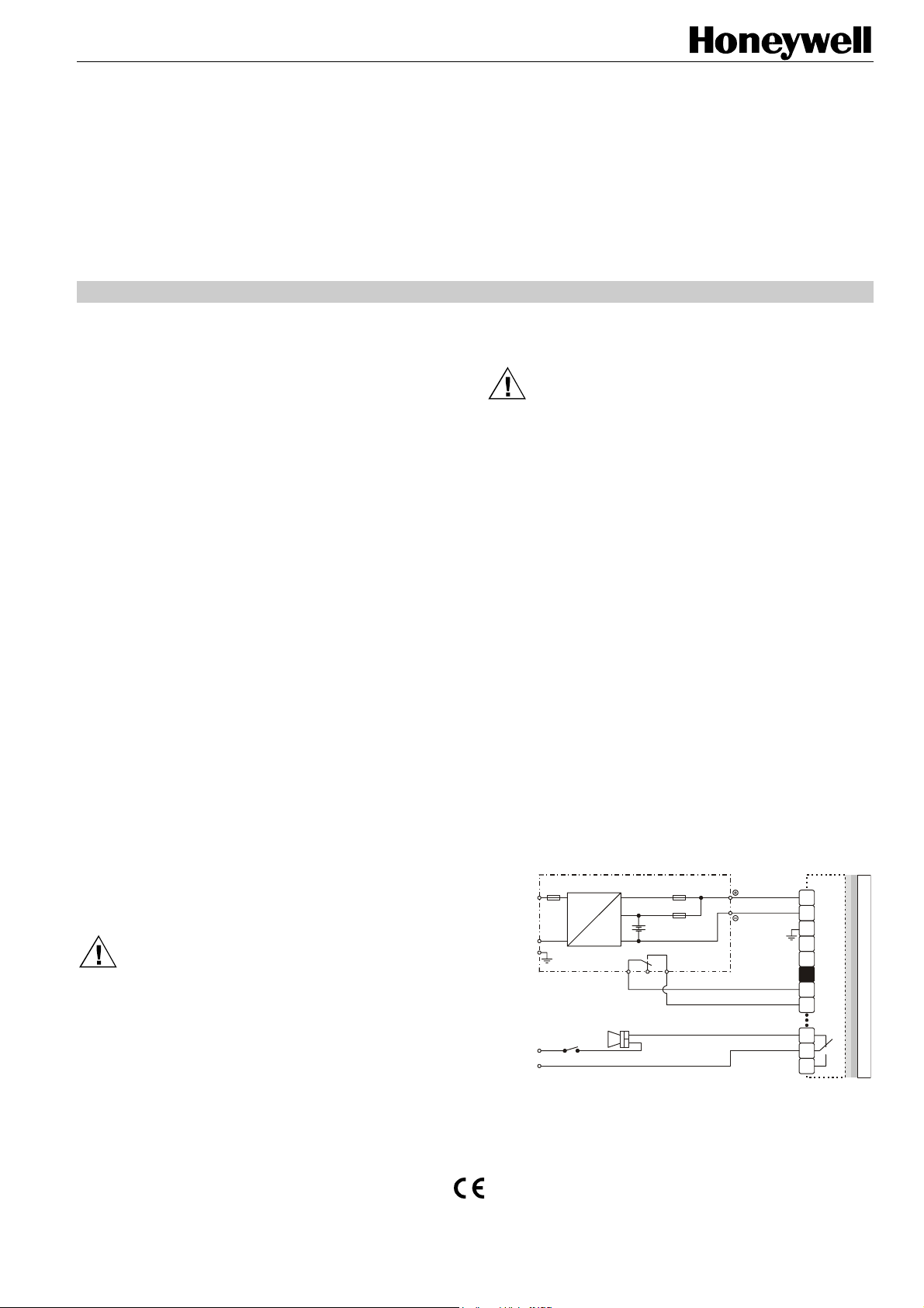
Special Case 1 / Sonderfall 1
Fig. 1 pertains to the wiring of the RIN-APU24 to an XP502
powering XC5010C / XC6010 controllers equipped with
internal modules, but not connected to Distributed I/O's.
NOTE: When LED (L3) is lit, this indicates that the
XC5010C / XC6010 controllers are running on
battery power.
NOTE: The output of the RIN-APU24 must not be
connected with any other devices.
Abb. 1 bezieht sich auf die Verdrahtung des RIN-APU24 mit
einem XP502, das XC5010C bzw. XC6010 Regler mit Strom
versorgt, die mit internen Modulen ausgestattet, jedoch nicht
mit Verteilten I/O's verbunden sind.
Hinweis: Das Leuchten von LED (L3) weist darauf hin, daß
die XC5010C bzw. XC6010 Regler mit
Batteriestrom betrieben werden.
Hinweis: Der Ausgang des RIN-APU24 darf nicht mit
anderen Geräten verbunden werden.
1 L
230V~
(+6%/-10%)
50...60 Hz
2 N
3 PE
max.
24 V~
3 A
RIN-APU24-2
1.6 A 4 A
AC
battery
DC
switched power supply
Schaltnetzteil
watchdog
Batterie
battery operation
C4 NC6 NO5
4 A
Batteriebetrieb
8, 9
24 Vdc
10, 11
Fig.1. XC5010C / XC6010 with internal modules
Abb. 1. XC5010C / XC6010 mit internen Modulen
P502
LN21
3
4
5
6
7
8
16
K1
17
18
XC5010C or XC6010C CONTROLLER
® U.S. Registered Trademark MU1B-0258GE51 R1108
Copyright © 2008 Honeywell Inc. All Rights Reserved
Page 2
RIN-APU24
X
X
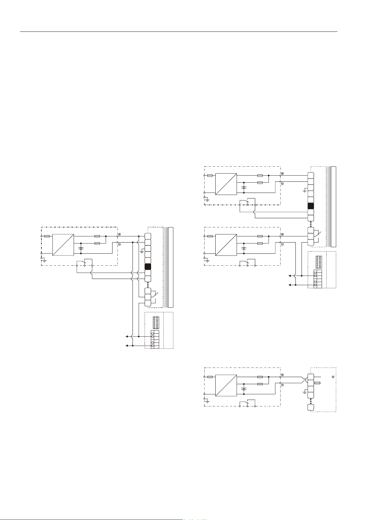
Special Case 2 / Sonderfall 2
Fig. 2 pertains to the wiring of the RIN-APU24 to an XP502
powering XC5010C controllers connected with Distributed
I/O modules, but not equipped with internal modules.
NOTE: In the case of the XC5010C, there must be no
connection between its GND and the GND of the
Distributed I/O modules.
Relay K1 ensures that the power supply of the Distributed I/O
modules will be switched OFF whenever the XP502 is
switched OFF.
Abb. 2 bezieht sich auf die Verdrahtung des RIN-APU24 mit
einem XP502, das den XC5010C Regler mit Strom versorgt,
die mit Verteilten I/O-Modulen verbunden, jedoch nicht mit
internen Modulen ausgestattet sind.
Hinweis: Im Falle des XC5010C darf es zwischen dessen
GND und dem GND der Verteilten I/O-Module
keine Verbindung geben.
Das Relais K1 gewährleistet, daß die Stromversorgung der
Verteilten I/O-Module immer ausgeschaltet wird, wenn XP502
ausgeschaltet wird.
16
17
18
1
3
4
5
6
7
8
XP502
L
N2
XSL511
1
2
3
4
5
6
24V
K1
DISTRIBUTED
~
1 L
230V~
(+6%/-10%)
50...60 Hz
2 N
3 PE
RIN-APU24-2
1.6 A 4 A
AC
battery
DC
switched power supply
Schaltnetzteil
Batterie
battery operation
C4 NC6 NO5
to other XSL511s of
the same controller
4 A
Batteriebetrieb
8, 9
24 Vdc
10, 11
Fig. 2. XC5010C with Distributed I/O modules
Abb. 2. XC5010C mit Verteilten I/O-Modulen
Special Case 3 / Sonderfall 3
Fig. 3 pertains to the wiring of the RIN-APU24 to an XP502
powering XC5010C controllers equipped with internal
modules and connected with Distributed I/O modules. In such
a case, two RIN-APU24 units are required.
The first RIN-APU24 is wired to the XP502, which powers
only the XC5010C controller. Repeat: It is not allowed to
power any other device with the XP502.
The second RIN-APU24 is wired to one or more XSL511
L
ONWORKS connector modules, which power the Distributed
I/O modules. The wiring of the second RIN-APU24 to relay K1
of the XP502 ensures that the power supply of the Distributed
I/O modules will be switched OFF whenever the XP502 is
switched OFF.
Abb. 3 bezieht sich auf die Verdrahtung des RIN-APU24 mit
einem XP502, das den XC5010C Regler mit Strom versorgt,
die mit internen Modulen ausgestattet und mit Verteilten I/OModulen verbunden sind.
Der erste RIN-APU24 ist mit dem XP502 verdrahtet, das
ausschließlich den XC5010C Regler mit Strom versorgt.
Nochmals: Es darf kein weiteres Gerät vom XP502 mit Strom
versorgt werden.
Der zweite RIN-APU24 ist mit einem oder mehreren XSL511
L
ONWORKS Verbindungsmodulen verbunden, die die Ver-
teilten I/O-Module mit Strom versorgen. Die Verdrahtung des
zweiten RIN-APU24 zu Relais K1 des XP502 gewährleistet,
daß die Stromversorgung der Verteilten I/O-Module immer
ausgeschaltet wird, wenn XP502 ausgeschaltet wird.
XC5010C CONTROLLER
1 L
230V~
(+6%/-10%)
50...60 Hz
2 N
3 PE
1 L
230V~
(+6%/-10%)
50...60 Hz
2 N
3 PE
(1) RIN-APU24-2
1.6 A
AC
DC
switched power supply
Schaltnetzteil
C4C4NC6
battery
Batterie
4 A
4 A
battery operation
Batteriebetrieb
NO5
(2) RIN-APU24-2
1.6 A
AC
DC
switched power supply
Schaltnetzteil
4 A
4 A
battery
Batterie
battery operation
NC6
NO5
to other XSL511s of
the same controller
Batteriebetrieb
Fig. 3. XC5010C with internal and DIO's
8, 9
24 Vdc
10, 11
8, 9
24 Vdc
10, 11
Abb. 3. XC5010C mit internen und VIO's
XCL5010
Fig. 4 pertains to the wiring of the RIN-APU24 to an XCL5010
controller.
I/O MODULES
Abb. 4 bezieht sich auf die Verdrahtung des RIN-APU24 mit
einem XCL5010 Regler.
230V~
(+6%/-10%)
50...60 Hz
1 L
1.6 A 4 A
2 N
3 PE
AC
DC
switched power supply
Schaltnetzteil
C4 NC6 NO5
battery
Batterie
4 A
battery operation
Batteriebetrieb
Fig. 4. / Abb. 4. XCL5010 + RIN-APU24
RIN-APU24-2
8, 9
24 Vdc
10, 11
1
3
4
5
6
7
8
16
17
18
1
2
3
4
14
P502
L
N2
XSL511
1
2
3
4
5
6
24V
CL5010
K1
~
24 Vac
24 Vac
XC5010C CONTROLLER
I/O MODULES
DISTRIBUTED
MU1B-0258GE51 R1108
2
Page 3

RIN-APU24
X
IMPORTANT
1. Terminals 3 through 14 of the XCL5010 are not needed
and are not to be used as auxiliary terminals.
2. In the case of the XCL5010, terminals 4, 5, and 6 of the
RIN-APU24 are not used.
WICHTIG
1. Klemmen 3 bis 14 des XCL5010 werden nicht benötigt
und dürfen nicht als Stützklemmen verwendet werden.
2. Klemmen 4, 5 und 6 des RIN-APU24 werden beim
XCL5010 nicht verwendet.
XL100C
Fig. 5 pertains to the wiring of the RIN-APU24 to an XL100C
controller.
Abb. 5 bezieht sich auf die Verdrahtung des RIN-APU24 mit
einem XL100C Regler.
55
56
57
58
COMMON
230V~
(+6%/-10%)
50...60 Hz
1 L
1.6 A 4 A
2 N
3 PE
RIN-APU24-2
AC
DC
switched power supply
Schaltnetzteil
C4 NC6
battery
Batterie
4 A
battery operation
Batteriebetrieb
NO5
Fig. 5. / Abb. 5. XL100C + RIN-APU24
8, 9
24 Vdc
10, 11
Excel Web
Fig. 6 pertains to the wiring of the RIN-APU24 to an Excel
Web controller.
Abb. 6 bezieht sich auf die Verdrahtung des RIN-APU24 mit
einem Excel Web Regler.
59
60
62
63
64
65
66
67
68
69
70
72
61
71
24 V
}
300 mA
10 V
}
10 mA
24 Vac
+/- 20% or
}
24...28 Vdc
1 L
230V~
(+6%/-10%)
50...60 Hz
2 N
3 PE
max.
24 V~
3 A
RIN-APU24-2
1.6 A 4 A
AC
battery
DC
switched power supply
Schaltnetzteil
watchdog
Batterie
battery operation
C4 NC6 NO5
4 A
Batteriebetrieb
8, 9
24 Vdc
10, 11
Fig. 6. / Abb. 6. XL Web + RIN-APU24
BATTERY / AKKU
When delivered, the APU-RIN24 and the storage battery are
not yet connected. Connect according to Fig. 6.
Im Auslieferungszustand besteht noch keine Verbindung
zwischen dem APU-RIN24 und dem Akku. Verbindung
gemäß Abb. 6 herstellen.
XL100C CONTROLLER
Fig. 6. Connect battery plug with board
Abb. 6. Batteriestecker mit Platine verbinden
MODELS / AUSFÜHRUNGEN
The RIN-APU24 is available in the following four different
models, distinguished solely by the technical specifications of
their built-in battery (a lead gel storage battery):
Der RIN-APU24 ist in den folgenden vier Ausführungen
erhältlich, die sich lediglich in den technischen Daten des
eingebauten Akkus (eines Bleigelakkus) unterscheiden:
• RIN-APU24-40 (40 A, 6.5 Ah)
• RIN-APU24-2 (2 A, 2 Ah)
• RIN-APU24-10 (10 A, 2 Ah)
• RIN-APU24-6 (6 A, 2 Ah)
See also Table 1 on page 4 for the specifications of the
battery of the RIN-APU24-2.
Siehe auch Tabelle 1 auf Seite 4 für die technischen Daten
des Akkus des RIN-APU24-2.
L Web
LN1
2
3
4
5
6
7
8
MU1B-0258GE51 R1108
3
Page 4

RIN-APU24
Table 1 / Tabelle 1. Technical Data of the battery of RIN-APU24-2/ Technische Daten der Batterie des RIN-APU24-2
main power Eingangsspannung 230 Vac (200...250 Vac)
input frequency Eingangsfrequenz 50 / 60 Hz
input current Stromaufnahme 0.1 ... 0.5 A
power consumption Leistungsaufnahme 100 VA
temperature range Temperaturbereich +14 ... +122 °F (-10 ... +50 °C)
output DC Ausgang DC
voltage Spannung 24 Vdc (21 ... 26.5 Vdc)
current Strom 2.0 A
current (short time) Strom (Kurzzeit) 3.0 A
maintenance-free accumulator wartungsfreier Akku
voltage Spannung 2 x 12 V
capacity Kapazität 2 Ah
size Größe
L X W X D L X B X T
battery lifetime Akku-Lebensdauer 6 years / 6 Jahre
min. duration of power supply XP502*
min. duration of power supply for XCL5010
Mindestdauer der Spannungsversorgung für
XP502*
Mindestdauer der Spannungsversorgung für
XCL5010
*incl. a fully-equipped XL5010C system (16 I/O boards plus MMI)
*einschließlich eines voll ausgerüsteten XL5010C-Systems (16 I/O-Module zuzügl. MMI)
7.81" X 7.81" X 3.15"
(200 X 200 X 60 mm)
15 min.
9 h
Manufactured for and on behalf of the Environmental and Combustion Controls Division of Honeywell Technologies Sàrl, Rolle, Z.A. La Pièce 16, Switzerland by its Authorized Representative:
Automation and Control Solutions
Honeywell GmbH
Böblinger Strasse 17
71101 Schönaich
Germany
Phone: (49) 7031 63701
Fax: (49) 7031 637493
http://ecc.emea.honeywell.com
Subject to change without notice. Printed in Germany
MU1B-0258GE51 R1108
 Loading...