

Page 1
Technical Note TN-151 02/08
ELECTROCHEMICAL SENSOR REPLACEMENT &
MAINTENANCE
This technical note describes sensor replacement and maintenance
procedures for electrochemical and combustible gas (LEL/TC)
sensors used in RAE Systems instruments, including MultiRAE,
QRAE, and VRAE. For technical specifications of sensors, see
Technical Note TN-114, and for handling LEL sensor poisons,
Technical Note TN-144. For CO sensor cross-sensitivity and filters,
see Technical Note TN-121.
GENERAL
• Prepare a clean workspace and wash hands well before
installing sensors. Greases and oils can cause sensors to
perform poorly. LEL sensors are particularly sensitive to
damage from silicone lubricants, including hand lotions.
• Turn off the power to the unit and remove the instrument cover.
• Disconnect the battery before replacing a sensor.
Warning: Failure to turn off the power during
replacement can cause damage to some
sensors. Failure to disconnect the battery
can cause the non-replaceable fuse in the
battery to blow.
Sensor Replacement Procedures
Remove the gas distribution plate, if any. Carefully pull the existing
sensor straight out.
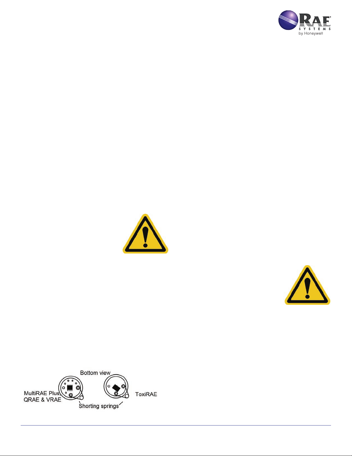
• Some electrochemical sensors are shipped with a shorting
spring connecting two of the large pins to keep the sensor
stabilized during storage. Remove any shorting spring before
installing the new sensor. Replace the spring if the sensor is
removed from the instrument for more than several minutes.
Lack of a shorting wire will not damage the sensor, but if it
is missing for more than about 10 minutes, the sensor may
require an hour or more to fully equilibrate after being installed.
Biased and LEL sensors do not have shorting springs.
• Insert the sensor by carefully lining up the sensor
pins with the sockets in the circuit board. To avoid
damaging the internal contacts, use caution and do
not bend the pins on the sensor. Bent sensor pins can
be carefully bent back using long-nose pliers.
• Do not push the sensors down too hard while
installing, as this may cause damage to the circuit
board components underneath the sensor.
• After reassembly, the unit may go into alarm if turned on
immediately. Allow about 10 minutes for the sensor to stabilize
in the unit before turning on the instrument. For maximum
accuracy, non-biased toxic sensors should be allowed to
stabilize for one hour before calibrating. Biased sensors
require a 24-hour stabilization time with batteries installed.
• Re-zero and recalibrate new sensors prior to use.
Biased Sensors (NO)
Nitric Oxide (NO) sensors require a voltage bias and must be
installed in position 1 of the MultiRAE Plus and positions 1 through
3 of the VRAE, and the bias switch must be turned on. See the
figures at the end of this Technical Note for the positions of the bias
switches and sensors.
Warning: Failure to install NO sensors in the
biased position can damage the sensors. Using
shorting springs on bias-type sensors can
damage the sensors.
Biased sensors require a 24-hour stabilization time with batteries
installed. If you receive a new unit with this sensor, install the
batteries and wait overnight before attempting to calibrate the
sensor. Units with rechargeable batteries must be kept at minimal
charge to main the bias on the sensor. If the sensors or batteries are
disconnected for more than a few seconds, it may require several
hours to again stabilize the sensor.
RAE Systems by Honeywell 877-723-2878 raesystems.com
RECALIBRATION
The MultiRAE remembers the last calibration on a given sensor
position. If a sensor is traded out, the new sensor needs about one
hour to equilibrate, and it must then be recalibrated. In the case
of a sensor with an electrical bias (NO), it must equilibrate about
1
Page 2
Technical Note TN-151 02/08
24 hours before calibrating. We recommend calibrating whenever
a sensor is removed, even if the same sensor is reinstalled in the
same location.
FILTERS
It is good practice to replace filters at the same time a sensor is
replaced. Filters may need replacement more frequently if clogged
or saturated. Filter replacement is indicated when the sensor begins
to respond slowly or take a long time to recover from an exposure. In
addition to the instrument inlet filters designed to remove particles
and water droplets, some sensors (for example, CO) need other
external filters for proper operation.
• ToxiRAE membrane filter & MultiRAE/
QRAE filter cartridges. Replace when visibly
dirty or when sensor response become slow.
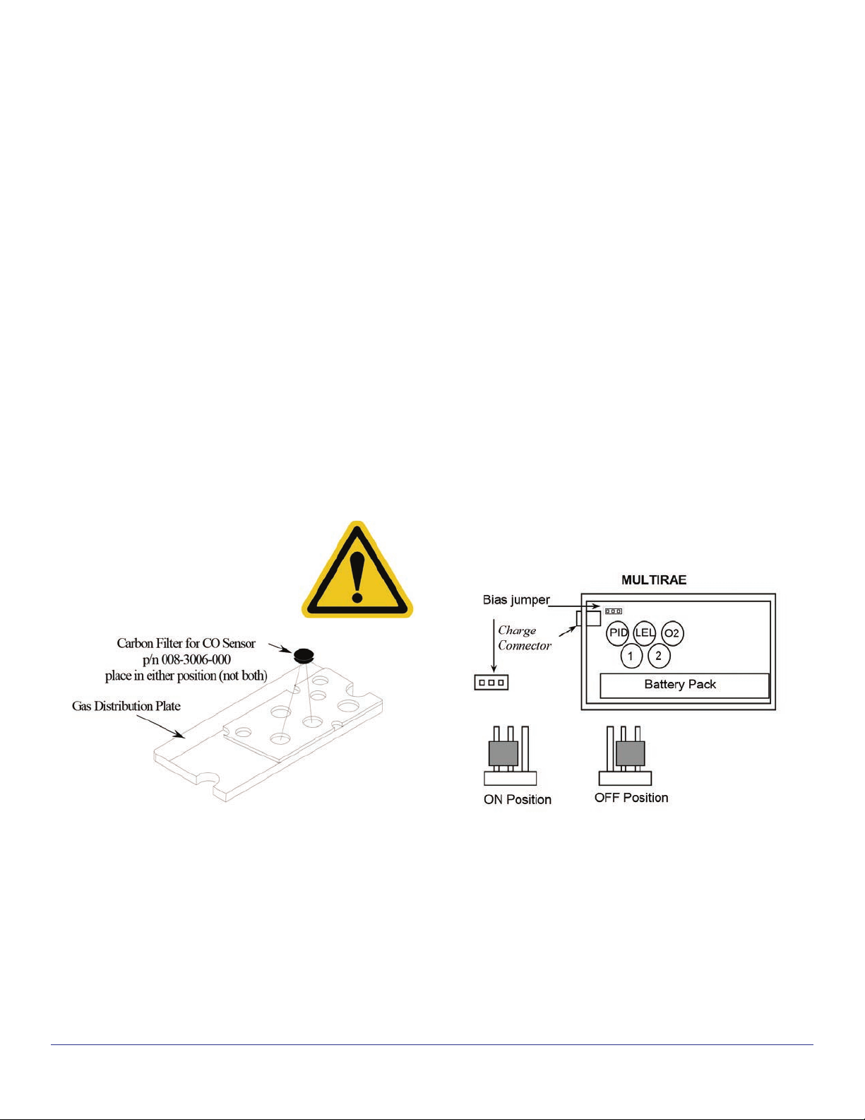
• CO sensor carbon filter. Replace when response to organic
vapors is noted or every six months, whichever comes first. This
filter is located in the MultiRAE, VRAE or QRAE cover plate.
• Remove the carbon filter if another sensor is used to
replace a CO sensor. For example, if an SO
or Cl2 sensor
2
is installed, the carbon filter removes these
gases and low readings are obtained.
Warning: Failure to remove the carbon filter
in the MultiRAE Plus cover plate for sensors
other than CO may result in low readings.
sensors are particularly sensitive to high relative
• Cl
2
humidity and may burst if stored in a refrigerator.
• Oxygen sensors are always on and are being consumed
by ambient air. These sensors are shipped in oxygenimpermeable bags. The shelf life can be extended by k
eeping the sensor in the impermeable bag until it is used.
• Replace shorting springs on non-biased sensors
for rapid start-up when reinstalled.
• Store LEL sensors away from possible catalyst poisons
such as silicone-containing greases or rubbers,
sulfur compounds, and chlorine compounds.
• The plastic containers used to ship sensors are not
air-tight and do not provide long-term protection
from humidity extremes, O
, or LEL poisons.
2
BIAS SWITCH LOCATIONS
Nitric Oxide sensors should be placed in position 1 on the MultiRAE
and positions 1 to 3 on the VRAE. The MultiRAE Plus uses a jumper
moved from the right two pins to the left two pins to turn on the
bias. The VRAE uses three switches pushed up towards the sensors
to turn on the bias. The MultiRAE can have one biased sensor and
the VRAE up to three.
STORAGE
Sensors can dry out or burst if stored at very low or very high
relative humidity, respectively. To maximize sensor life, store sensors
and instruments indoors in a climate-controlled building. Note other
special conditions:
RAE Systems by Honeywell 877-723-2878 raesystems.com
MultiRAE top view with c over plate removed showing location of
bias jumper and sensor positions.
2
Page 3

Technical Note TN-151 02/08
VRAE Internal view showing location of bias switch position and
sensor positions
Sensors PGM-7800 PGM-7840
Gas Bias
CO Off OK OK OK OK
H
S Off OK OK OK OK
2
SO
2
NO ON
NO
2
Cl
2
ClO
2
NH
3
HCN Off OK OK OK OK
PH
3
Off OK OK OK OK
Off OK
Off OK
Off OK
Off
Off OK OK OK OK
Tox1,2
Loc.
OK bias onOK bias
OK bias
off
Tox3 Loc.
on
Not
allowed
Not
allowed
Not
allowed
OK bias
off
Tox1,2,3
Loc.
OK
OK
OK
OK
OK bias
off
Tox4 Loc.
Not
allowed
Not
allowed
Not
allowed
Not
allowed
OK bias
off
INTERCHANGEABILITY
Single Sensor in Different Instruments
• Sensors for the MultiRAE, QRAE, QRAE Plus, and VRAE are
interchangeable among instruments, except for the LEL/VOL
sensor. The MultiRAE and QRAE use the 4R sensor only (p/n
008-1171-002), the VRAE uses either the 4R (p/n 017-1171-
000) or 4R/TC sensor (p/n 017-1172-000), and the QRAE Plus
uses the 3R/TC sensor (p/n 016-1171-000 or 016-1172-000).
The CO
sensor can only be used in the MultiRAE IR.
2
Different Sensors in a Single Instrument
• In the MultiRAE and VRAE, all sensors including the HCN
and PH
sensors (p/n 008-1117 and 19) are interchangeable.
3
Thus, any combination of sensors is possible, except that
the MultiRAE can have only one biased sensor (NO) because
there is only one bias position. In the VRAE, sensors with
a negative current (NO
, Cl2, and ClO2) cannot be placed in
2
position 3, and in the VRAE, sensors with a bias or negative
current cannot be placed in position 4 (see table below).
• The QRAE is limited to the four standard sensors LEL/O
/CO/H2S.
2
EXTENDED CALIBRATION TIMES
Slowly responding sensors listed in the table below may require preexposure of the sensor to the gas immediately before initiating the
calibration sequence. Some firmware versions use a fixed 60-second
calibration time; some newer versions automatically apply the full
calibration time. After completing the zero calibration, expose the
unit to the gas for the pre-exposure time listed below if a 60-second
countdown time is programmed in the unit. In many cases when a
pre-exposure is performed, the unit gives a warning message “No
gas...” when calibration is initiated. Simply push the [Y/-] button to
bypass the warning and proceed wit the calibration.
Total
Calibration
Time (sec)
2
3
Response Time
t
(sec)
90
150 150 90
60 120 60
≤40 60 0
Sensor
HCN 200 230 170
CLO
, NH3,
2
COCl
, PH
CL
2
CO, H
S, SO2,
2
NO, NO
, LEL,
2
VOL
Pre-exposure
Time for 1-min
Calibration
Time
RAE Systems by Honeywell 877-723-2878 raesystems.com
3
 Loading...