

Page 1
RABO
®
Rotary Gas
Meter
Instruction
Manual
Page 2

Page 3
ELSTER
RABO® Rotary
Gas Meter
3 Honeywell
RABO® Rotary
Gas
Meter
Table of
Contents
1. General Information 3
2. Intended Use and Application 3
3. Operating Principle 3
4. Receiving, Handling and Storage 4
5. Installation 4
6. Start-up/Commissioning 6
7. Decommissioning and Removal 6
8. Inspection and Maintenance 6
9. Testing 6
10. Technical Data 8
11. Index 12
12. Pulser 14
13. Thermowell 15
14. Instrument Drive (ID) 15
15. Auxiliary Equipment Mounting 17
16. Direct mount TCI or EC350 18
17. Troubleshooting 19
1. General Inform ation
This manual covers the installation, operation
and
maintenance for the Elster Instromet RABO Rotary
Meter.
Refer
to EAM-TB
5900 for additional information.
2. Intended
Use and Application
Elster RABO meters are suitable for measur ing most types of
clean, dry, non-corrosive common gases. They are NOT
intended
for
use on biogas,
sewage
gas, oxygen, acetylene
or liquids of any kind. Product life and measurement accuracy
can be
affected
by contamination in
the gas stream. Periodic
servicing will prolong
the life and performance of
the meter.
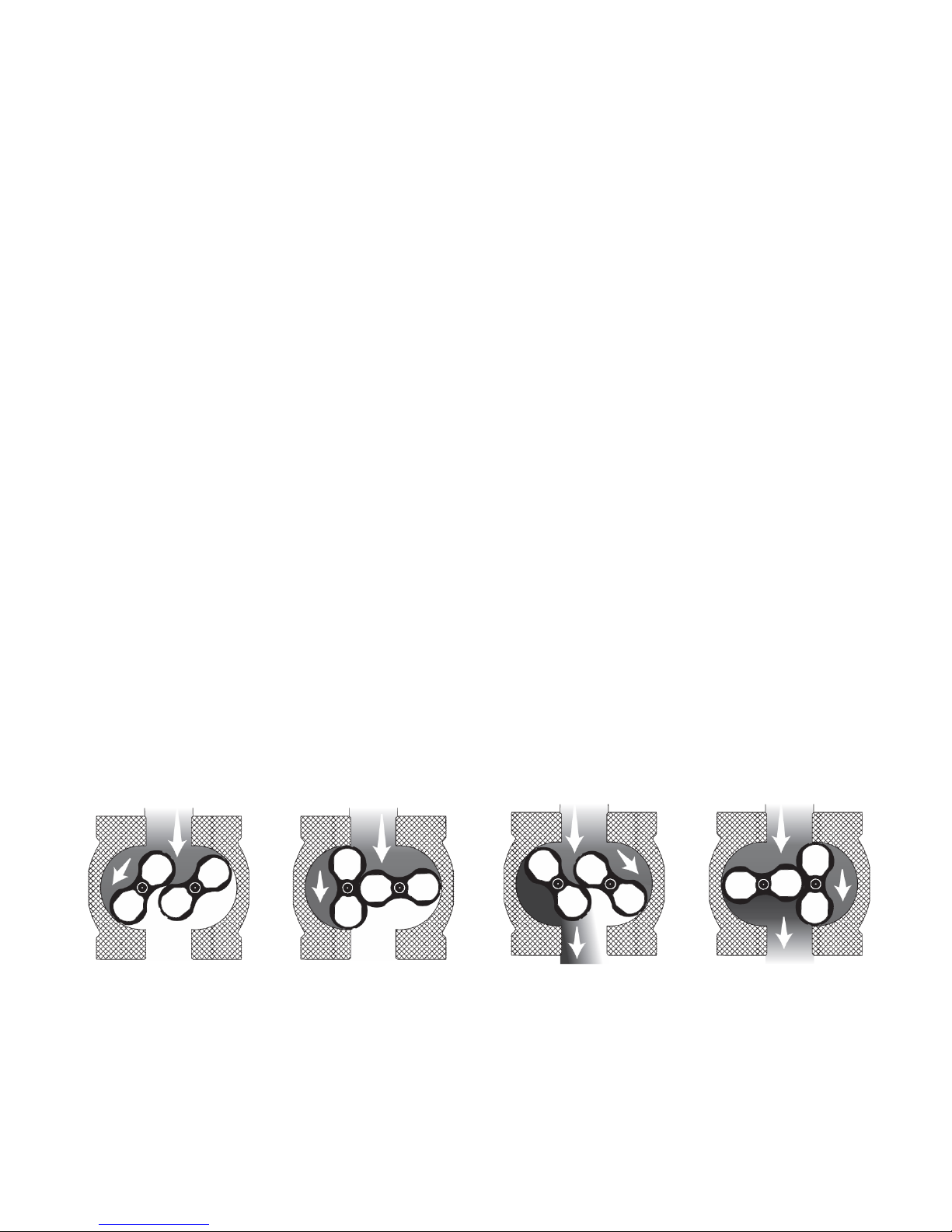
3. Operating Principle
The RABO
meter ut
ilizes positive displacement principle of
operation which
makes volumetric measurements by
displacing finite volumes of
gas. The positive displacement
occurs w
ithin a cavity formed between the meter’s internal
housing
and its rotating impellers. The counter-rotating
“figure-
8”
impellers [Figure
1]
turn as a result of
pressure
drop across
the
meter’s inlet and outlet created as downstream
gas is
consumed. The rotating
impellers
separate
the flowing gas
into small , fin ite volumes and are counted using a mechanical
index. The
RABO
meter
has no wearing parts
because
precision
clearances between
the impellers and meter body
are maintained by timing
gears,
which are
designed
to
enhance
long term accuracy. Combining
adequate
filtration
and periodic
maintenance, a RABO
meter will remain accurate
over many
years.
As the
left
impeller
rotates
toward the
vertical
position, gas enters the
cavity
created
between the
impeller and the
housing.
When the
left
impeller
reaches
the vertical
position, a
finite
volume of gas is
captured in
the
left
cavity.
As the impellers continue
to turn, the volume of gas
in the
left cavity
is
discharged.
Simultaneously, gas is
entering the space
between
the right impeller
and
housing.
After
further rotation,
the
right impeller
becomes
vertical
and a
finite
volume of gas is
captured in
the
right
cavity.
Figure 1. Operating Principle
Page 4
ELSTER
RABO® Rotary
Gas Meter
4 Honeywell
4. Receiving, Handling and Storage
Elster
RABO
meters should
be handled with care to protect
the
product from damage.
If
the package shows evidence
of damage
through mishandling in transit,
you should notify
the
shipper immediately, file
a claim with the carrier
and notify
your
Elster supplier.
Damage to internal
components may occur wit
hout
visible external
damage.
All
new meters should
be
inspected and
checked for free rotation of
the impellers
by
lightly blowing into the inlet of
the meter. This
slight
air
pressure should
cause the impellers
to rotate freely and
come to a stop
slowly.
NOTICE
DO NOT
attempt to make any repairs. Tampering with the
meter
may void warranty coverage.
If
a meter shows signs of external
damage,
or
if
the
impellers do
not rotate freely,
contact your local Elster sales
representative for return instructions.
Elster
RABO
meters are supplied
with oil in a separate
containe
r. A material safety data sheet (MSDS) is available
upon
request.DO NOT
put oil in the meter until
it is installed
and
leveled in the gas piping system. Meters containing oil
that are transported or
not installed level may lead
to
contamination of the measurement chamber, and
will impact
accuracy.
Store Elster RABO
meters in their original shipping container
in a dry location until installation.
If prolonged
storage is
experienced, RABO
meters should
be tested for accuracy
before installation.
5. Installation
Elster
RABO
meters can be installed in horizontal or vertical
(top inlet) piping configurations. Vertical (top inlet) piping is
preferred
because
it
enables
the meter to pass
contaminants
more freely through the meter .
All
piping should
be properly
supported
and aligned to eliminate any strain on
the meter, which may
cau
se
the impellers to bind.
Recommended
piping practices include a
filter
or strainer on
the
inlet of the meter and non-lubricated isolation valves. A
bypass
line will facilitate
maintenance
and removal of the
meter
and provide uninterrupted gas supply.
The meter should not be installed lower than the outlet pipe
run.
If it
is
necessary
to install the meter lower than the outlet
pipe run, installation of a drip leg in the outlet piping to capture
condensate
is
recommended.
The meter should never be
located at the lowest point in the system.
A restricting
orifice
can also be installed at least 4 pipe
diameters downstream
of the outlet of the meter to prevent
the meter from flowing excess capacity. Warranty does not
cover failures due to excess
flow
conditions.
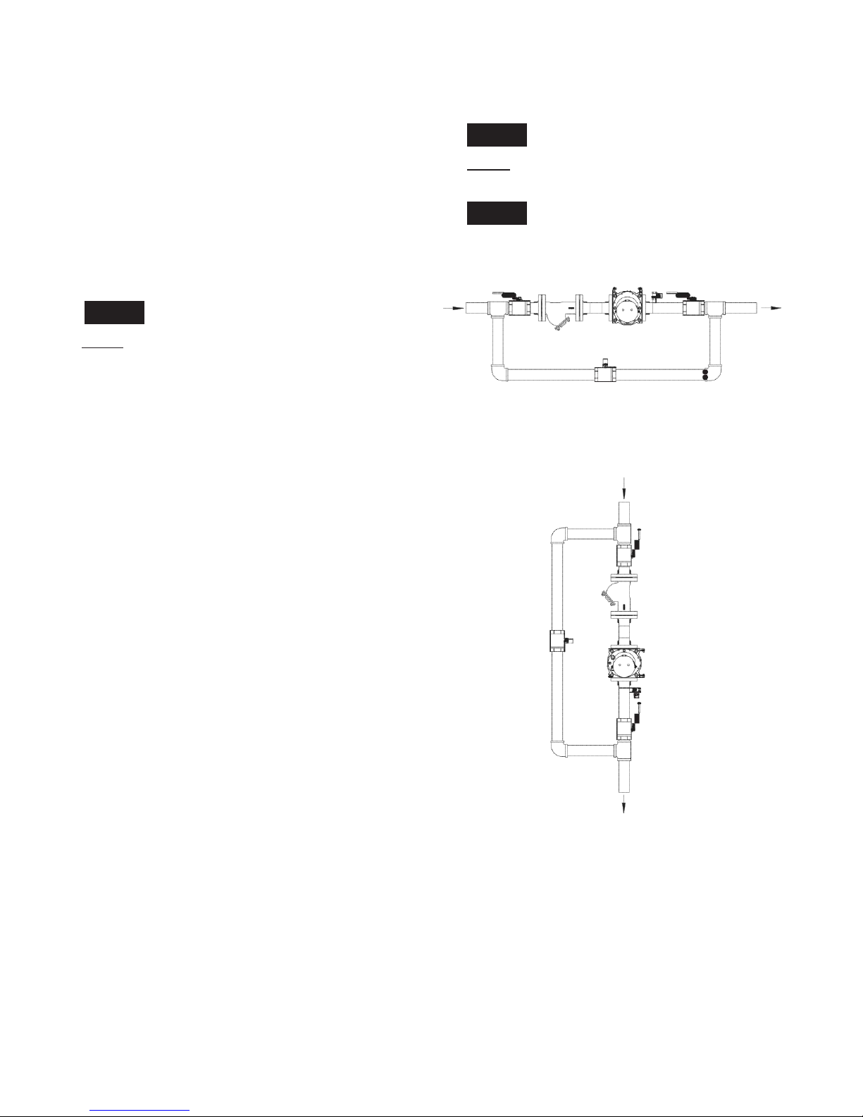
a) Piping Configurations
[Figures
2, 3 and 4]
NOTICE
DO NOT weld piping while meter is installed in
the piping system.
NOTICE
If
hydro testing, remove the meter from the piping
system.
Figure
2. Horizontal installation, side vie
w
Figure
3. Vertical installation, side view
Page 5
ELSTER
RABO® Rotary
Gas Meter
5 Honeywell
b) Mounting
1) Always follow your company’s
procedures, an
d
applicable local codes and ordinances.
2) Ensure
gas valves
are closed.
3) Ensure
the upstream piping is clean
and free of any
debris.
4) Remove protective caps from
meter inlet and outlet
prior
to installation.
5) Ensure
the impellers
turn freely.
6) Ensure
the direction of flow using the arrow on th
e
nameplate.
7) Ensure
the meter orientation is correct. Impeller
shafts must be horizontal [Figure 4].
Figure
4. Side vie
w
8) Connect the inlet and outlet pipe
flanges usin
g
appropriate bolts and gaskets. Inlet and outlet pipe
flanges s
hould
be parallel and should
not introduce
any bind
on the meter body when tightened.
9) Level meter to within 1/16“per foot in all directions an
d
tighten flange bolts evenly (maximum 80ft-lbs).
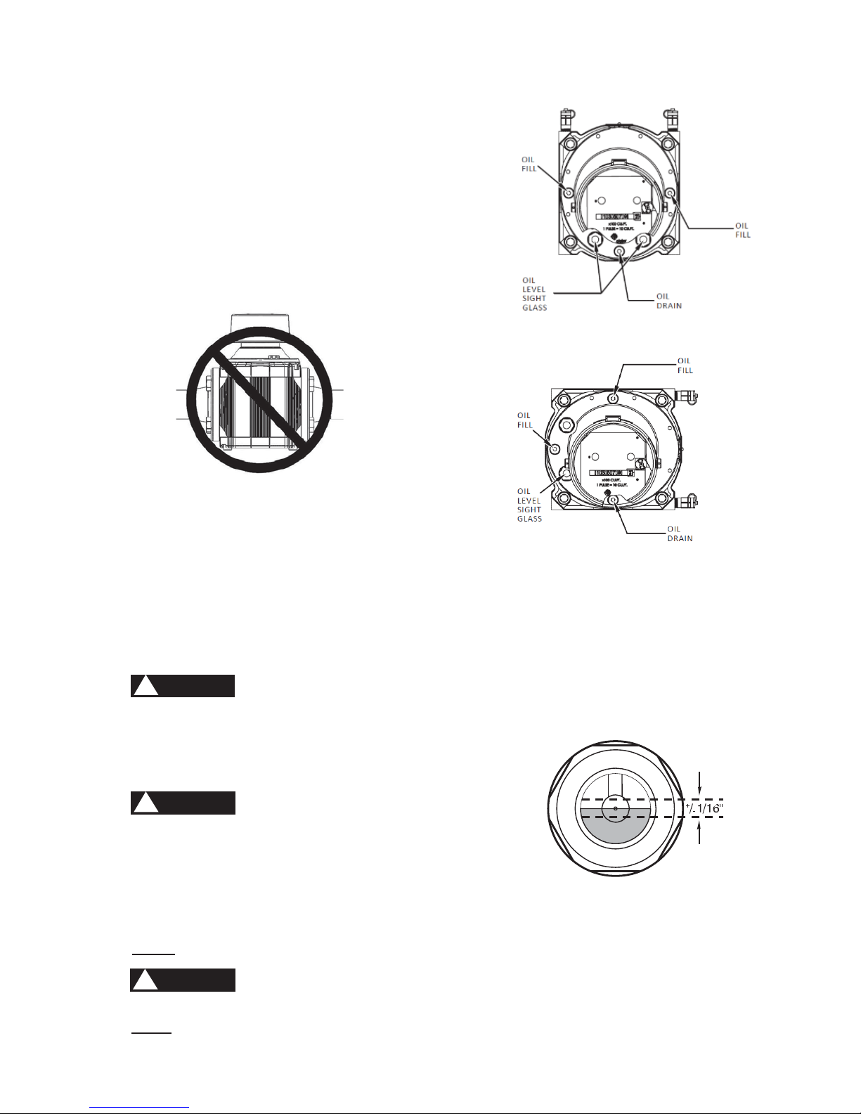
c
) Adding O
il
Figure
5. Horizontal installation
Figure
6. Vertical installati
on
!
WARNING
Add
oil only
to the inde
x end of the meter
.
1) Ensure gas valves
are closed
and meter and
piping are depressurized.
!
WARNING
Failure to depressurize the meter prior
to
removing meter and/or components could result
in persona
l injury and/or property damage.
2) Remove oil
fill plug in the counter end case cover
using a
5mm hex key [Figures 5 and 6].
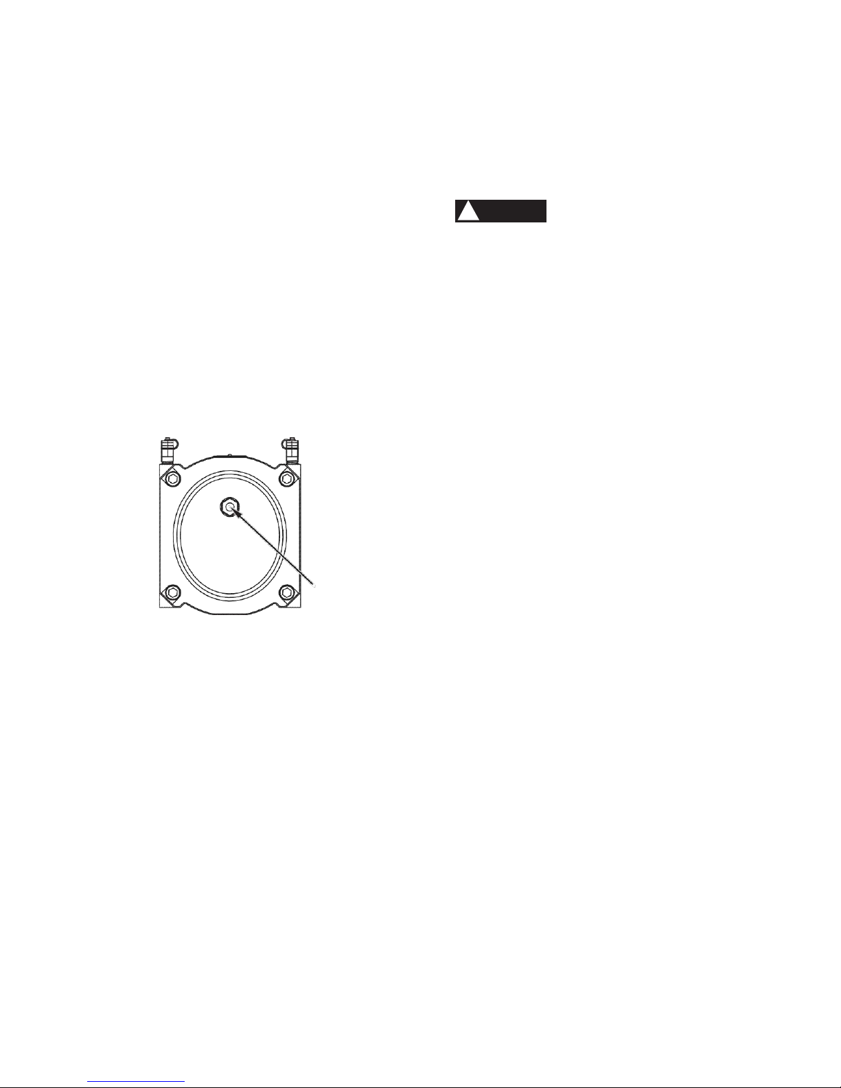
3) Using the supplied syringe
and oil, slowly
add oil until
it is +/-1/16“of the center of
the sight glass [Figure 7]
.
DO NOT OVERFILL. Only use Shell Morlina lubricating oil.
!
WARNING
Figure
7. Sight glass
DO NOT remove any sight glasses. No maintenance
can be performed throug
h these openings.
4)
Reinstall
the
oil fill
plug.
Page 6
ELSTER
RABO® Rotary
Gas Meter
6 Honeywell
6. Start-up/Commissioning
7. Decommissioning and Removal
After
the meter has been properly installed,
it
is important to
use
extreme care during start-up to mitigate adverse
conditions
that
can
damage
the
meter.
a) Ensure
that the maximum operating
pressure of the
meter
will
not be exceeded.
b) Always follow your company’s
procedures,
and local
codes
and ordinances.
c) With
the meter run’s inlet
and outlet valves closed,
open
the
bypass valve and pressurize the piping system.
d) With
the meter outlet valve closed, slowly
open the
meter inlet valve not to exceed 5 psig
per second until
pressure is equalized throughout the meter piping
system.
Rapid pressurization can cause an over
-
speed condition and can
damage
the meter.
Damage
will
not be covered under warranty. When
the meter
piping system
pressure is stabilized,
open
the
inlet valve completely.
e) Slowly
open the meter’s outlet valve until the meter starts
to operate at
low
speed.
Meter
speed
can be seen
through
the view port located on the back of
the meter
[Figure 8].
VIEW PORT
(DO NOT REMOVE )
Figure
8. Back of meter
a) Always follow your company’s
procedures,
and local
codes
and ordinances.
b
) Slowly open bypass valve.
c) Slowly close
the meter’s outlet valve,
then the inlet valve.
d) Slowly, completely depressurize
the meter piping.
!
W
ARNING
Failure to depressurize the meter prior
to removing
m
eter and/or components could result in personal
injury and/or property damage.
e) Drain oil from the index end case cover and dispose of
the
o
il in
accordance with applicable regulations.
f) If removing
the meter from
the piping
system, loosen
flange bolts. Ensure
meter is properly supported before
removin
g bolts completely.
8. Inspecti
on
and Maintenance
It is recommended
to inspect Elster RABO
meters periodically
to h
elp
ensure accurate performance over a long period of
time. Maintenance intervals can be derived from inspection
criteria.
Routine inspections s
hould include:
a) Checking
to ensure the meter is level in all plane
s
b) Listening for abnormal sounds in
the meter
c) Checking oil level and clarity
— oil s
hould
be red and clea
r
d) Checking index
movement
if
gas is flowing
e) Checking f or le aks
f) Tes ti ng t he met er’ s differential pressure
Routine maintenance should include
:
a) Changing the oil if th e col or bec om es dark
b
) Adding oil
if
the color is
red and clear, but below the
recommended level
f)
Operate the meter at low flow for 1
to 2 minutes
to verify
proper operation.
If
the index does not start registration,
or if
you hear knocking or scraping
sounds coming from
the
meter, stop the flow and follow appropriate
decommissioning procedures before removing the
meter
from the line.
g)
If operation is satisfactory, gradually
open the meter’s
outlet valve
to the full open position.
h) Slowly close
the bypass valve.
i)
Check the meter connections for leaks using comm
on
industry practices.
j) Clock the meter (see Index section 11c)
to confirm
the flow
rate is not exceeding
the maximum capacity of
the
meter.
k) Perform and record the meter’s differential
pressure
(see Testing section 9b).
9. Testing
Elster
RABO
meters should
be tested in accordance with
applicable governing standards. The accuracy of
a meter
can
only be determined by comparing results to a traceable
reference, typically a sonic nozzle, bell, piston or transfer
prover. Accuracy may
be done on site using transfer provers,
and
typically requires removal for testing
with other
tec
hnologies.
Differential pressure testing is
a method of determining
w
hether the performance of
a rotary meter may have
changed
over time, and can be done on site while
the meter
is operating under
pressure. Baseline data must be captured
during
initial
start-up to which future data can be compared.
a) Proving
When testing a meter on a prover, the meter
temperature, pressure
and volume
are necessary
inputs for the provin
g device. The
meter temperature is
obtained by a temperature probe installed
near the inlet
of the meter. A thermowe
ll
can be installed in the meter
run
piping or on the meter itself to facilitate installation of
the
temperature probe. The
meter
pressure should
come
from the meter differential pressure taps.
Page 7

ELSTER
RABO® Rotary
Gas Meter
7 Honeywell
Pressure test ports are provided for simplified pressure
c
onnections [Figure 9].
!
W
ARNING
Below
45OF
the
neoprene
core of
the Pressure test port
s
does not recover its original shape
as rapidly as
it would
at temperatures
above
45OF. Therefore,
upon removal
of the probe used for
pressure
or temperature
readings, the valves
may not close fully
and immediately
or the
valves may remain slightly
open until the operating
temperature is
above
45OF. Duration of
probe insertion
and
pressure
are also factors in the rate of valve
closing. For this reason, plugs s
hould
not be used in
applications
where discharging gas or liquids would
create a hazard.
The gasketed cap is supplied
to
eliminate the small
amount of leakage that may occur
at
lower temperatures after probe insertion and
removal. The cap should
be left
on the plug
at all times
and tightened to deter unauthorized removal. Special
care s
hould
be taken to
assure
that readings
are taken
in the shortest space of time and that a probe is
never
left in a plug for
a period of hours or days. Severe
deformation of
the valves
may occur
if
the probe is left in
the
plug for a long period of time.
PRESSURE TEST
PORTS
Figure
9. Pressure test ports
Typically,
when proving a meter, both the meter
pressure
and
meter differential
pressure
are used and recorded.
The RABO meter differential
pressure
ports are not full
bore and
mos
t temperature
probes
will
not
fit
through
into the gas stream. Insta
lling
the temperature probe in
the
provided thermowe
ll
ports is recommended.
The
meter volume is determined
though a device
that
senses the meter revolutions. An optical pickup
can be
used on
the index proving wheel or an index pulser
may
be
used.
On-site proving, performed in-line, also requires
c
onnections
that allow air flow through the meter to the
prover.
This is accomplished
by use of pipe Tees
upstream and downstream of
the meter. A bypass loop
is
recommended for uninterrupted gas supply to the
customer.
While performing
an accuracy test, the meter is
tested fo
r
a specified volume of gas at each flow rate test point.
Poor repeatability at a given rate may be
caused
by a
test
volume that is
too small.
It
the meter does not repeat
w
ithin acceptable limits (0.1%), try increasing
the test
volume and retesting the meter. Most companies have
developed
test plans that include the volume of gas for
each
size meter at a given flo
w rate. Consult
your Elster
representative for applicable volumes.
b) Differential Pressure Testing
A differential
pressure
test is
not an accuracy test, but
it
can
be used to
gauge
the relative performance of the
meter.
Rotary meters are made from solid parts, machined
to
tight tolerances with close clearance fits, and the energy
it takes to turn the meter is generally used to overcome
the
friction of the bearings
and other rotating
parts.
If
this friction value increases,
it will
take more energy to
overcome
it. This additional
energy is measured
as an
increased pressure
drop across the meter.
The increased friction is
caused
by contamination of the
measuring
chamber and/or bearings.
Contamination in the measuring chamber can cause th
e
meter components to
wear against each other.
Contamination in
the bearings
makes them harder to
turn. Comparing
the
pressure
drop reading when the
meter
is ne
w to the reading collected after time allows
the
performance
to be monitored.
RABO
meters are supplied
with Pressure test ports
installed in the meter differential
pressure
ports [Figure
9]. This facilitates differential meter testing.
A differential
pressure
test is performed using a differential
pressure
manometer. The test is
to
measure
the
pressure
drop
across the meter at a
given flow rate, under known
operating conditions at a known date
and time.
The
meter differential curve of flo
w rate vs
pressure is
not linear. Testing
at multiple flo
w rates is suggested. It
is preferable to test at 3 rates between 25% and 100%
of flow
if possible. Differential pressure
tests at flow rates
under 25% are hard to interpret
because
the meter
differential
pressure at the lower flow rates is quite small.
The error in measurement is almost
as large as the
reading itself.
The
meter differential
pressure is also a function of lin
e
pressure
and increases as line
pressure increases.
Testing
the meter at the same conditions (line
pressure
and flow rates) yields comparable data.
A
change in
the differential
pressure indicates a
change in performance. Testing
has shown that a 50%
increase in
meter differential
pressure (at flow rates over
25%), indicates almost a 1.0% change in
meter
accuracy. Baseline data must be captured during initial
start-up to w
hich future
data can be compared.
If
the differential
pressure
test shows an increase in the
meter
pressure
drop at a given flow rate of
more than
50%
from the original value (1.5
x original value),
then
it
is recommended
that the meter be removed and
serviced.
The frequency of deferential testing is
at the discretion of
the user.
Page 8

ELSTER
RABO® Rotary
Gas Meter
8 Honeywell
10.
Technical
Data
a) Performanc
e
Units
3.5M/G65
5.5M/G100
9M/G160
14M/G
250
Rangeab
ility
90:1
160:1
160:1
160:
Start Rate
acfh [a
m3/h]
1.3 [0.04]
0.9
[0.03]
2.5 [0.07]
2.5 [0.07]
Stop Rate
acfh [a
m3/h]
1.1 [0.03]
0.8
[0.02] 1.9 [0.05]
2.3 [0.07]
Flow Rate
at ½“ w.c.
DP, Gas
acfh [a
m3/h]
2,715 [77]
4,074
[115] 5,722 [162]
6,740 [191]
Differential
Pressure at 100% Flow Rat
e
in.w.c. [mBar
]
1.46 [3.64]
1.23 [3.06] 1.70 [4.23]
2.65 [6.60]
Note: Values
are for air, except Flow Rate at ½“w.c.
DP, which are natural gas values
.
b) Sizing Chart
Using
the chart below, select the appropriate
meter by using the Maximum Instantaneous Flow Rate (scfh) and the
Minimum Operating
Pressure (psig)
at any given point in time.
Example: A flow rate of
25,000 scfh
and an operating
pressure
range of 75–100 psig would require a 5.5M meter
based
on a
75
psig minimum inlet pressure.
Model
3.5M/G65
5.5M/G100
9M/G160
14M/G
250
psig [Barg]
Corrected Capacity in scfh
[sm3/h]
0.25
[0.0]
3,500
[100
]
5,500
[160
]
9,000
[
250
]
14,
000
[
400]
2
[0.1]
3,900
[110
]
6,100
[170]
10,
000
[
280
]
15,
600
[
440]
5
[0.3]
4,600
[130
]
7,200
[
200
]
11,900
[
340
]
18,
400
[
520]
10
[0.7] 5,800
[160
]
9,100
[
260
]
14,
900
[
420
]
23,200
[
660]
20
[1.4]
8,200
[
230
]
12,
800
[
360
]
21,
000
[
590
]
32,700
[
930]
30
[2.1]
10,
500
[
300
]
16,
600
[470]
27,100
[770
]
42,200 [1,190]
40
[2.8]
12,
900
[370]
20,300
[570]
33,200
[
940
]
51,700 [1,460]
50
[3.4]
15,
300
[
430
]
24,000
[
680
]
39,300
[1,110
]
61,
200 [1,730]
60
[4.1]
1
7,700
[
500
]
27,800
[790
]
45,500
[1,
290
]
70,700 [2,000]
75
[5.2]
21,
200
[
600
]
33,400
[
950
]
54,600
[1,
550
]
85,000 [2,410]
100
[6.9]
27,200
[770
]
42,700
[1,210]
69,900
[1,
980
]
108,700 [3,080]
150
[10.3]
39,100
[1,110
]
61,
400
[1,740]
100,
400
[2,
840
]
156,
300 [4,
430]
175
[12.1] 45,000
[1,270]
70,700
[2,
000
]
115,700
[3,
280
]
180,
000 [5,100]
250
[17.2]
62,800
[1,780]
98,700
[2,790]
161,500
[4,570]
251,
300 [7,120]
290
[20.0]
72,300
[2,
050
]
113,700
[3,
220
]
186,
000
[5,270]
289,300 [8,190]
Note:
All capacities based
on 14.4 psia atmospheric pressure, 14.73 psia base pressure, and
60OF
base temperature.
Page 9

ELSTER
RABO® Rotary
Gas Meter
9 Honeywell
c) Dimensions and Weight
s
RABO standard:
Units
3.5M/G65
5.5M/G100
9M/G160
14M/G
250
A
in. [mm]
6.75
[171]
6.75 [171]
9.5 [241]
9.5
[241]
B
in. [mm]
7.56 [192]
7.56 [192]
10.08 [256]
10.08 [256]
C
in. [mm]
8.63 [219]
8.63 [219]
10.75 [273]
10.75 [273]
D
in. [mm]
3.78
[96]
5.43 [138]
5.16 [131]
6.14 [156]
E
in. [mm]
7.52 [191]
9.17 [233]
10.67 [271]
11.65 [
296]
F
in. [mm]
11.26 [
286]
14.61 [371]
15.83 [402]
1
7.76 [451]
G
in. [mm]
3.78
[96]
3.78
[96]
5.04 [128]
5.04 [128]
Nom. Pipe Size* in. [mm]
2
3
3
4
Bolt Size, H
5/8“ - 11
5/8“ - 11
5/8“ - 11
5/8“ - 11
# Bolts/Flange
4
4
4
8
Bolt Circle, J in. [mm]
4.75
[121]
6.00
[152]
6.00
[152]
7.50 [191]
Shipping Weight
Ibs. [kg]
29.8
[14]
37.7
[17]
73.9
[34]
82.3 [37]
Carton Size
in.
18.3L
x 10.6W x 12.6H
23.6L x 13.0W x 13.4H
[mm]
465L x 270W x
320H
600L x 330W x
340H
*ANSI Class 125/150 flat face flange c
onnection
Page 10

ELSTER
RABO® Rotary
Gas Meter
10 Honeywell
RABO-ID:
Units
3.5M/G65
5.5M/G100
9M/G160
14M/G250
A
in.
[mm]
6.75
[171]
6.75
[171]
9.5
[241]
9.5
[241]
B
in.
[mm]
7.56
[192]
7.56
[192]
10.08
[256]
10.08
[256]
C
in.
[mm]
8.78
[223]
8.78
[223]
11.30
[287]
11.30
[287] D in.
[mm]
3.78
[96]
5.43
[138]
5.16
[131]
6.14
[156]
E
in.
[mm]
9.53
[242]
11.23
[285]
12.72
[323]
13.67
[347]
F
in.
[mm]
13.31
[338]
16.66
[423]
17.88
[454]
19.81
[503]
Shipping Weight
lbs.
[kg]
32.3
[15]
40.2
[19]
76.4
[35]
84.8
[39]
Carton Size
[in.]
18.3L x 10.6W x 12.6H
18.3L x 10.6W x 12.6H
23.6L x 13.0W x 13.4H
23.6L x 13.0W x 13.4H
[mm]
465L x 270W x 320H
465L x 270W x 320H
600L x 330W x 340H
600L x 330W x 340H
Page 11

ELSTER
RABO® Rotary
Gas Meter
11 Honeywell
RABO-TCI:
Units
3.5M/G65
5.5M/G100
9M/G160
14M/G250
A
in.
[mm]
6.75
[171]
6.75
[171]
9.5
[241]
9.5
[241]
B
in.
[mm]
7.56
[192]
7.56
[192]
10.08
[256]
10.08
[256]
C
in.
[mm]
10.24
[260]
10.24
[260]
12.76
[324]
12.76
[324]
D
in.
[mm]
3.78
[96]
5.43
[138]
5.16
[131]
6.14
[156]
E
in.
[mm]
11.18
[284]
12.83
[326]
14.33
[364]
15.31
[389]
F
in.
[mm]
14.96
[380]
18.27
[464]
19.49
[495]
21.46
[545]
G
in.
[mm]
4.92
[125]
4.92
[125]
4.92
[125]
4.92
[125]
H
in.
[mm]
3.74
[95]
3.74
[95]
3.74
[95]
3.74
[95]
K
in.
[mm]
8.66
[220]
8.66
[220]
8.66
[220]
8.66
[220]
Shipping Weight
lbs.
[kg]
32.8
[15]
40.7
[19]
76.9
[35]
85.3
[39]
Carton Size
[in.]
22L x 12W x 16H
28L x 16W x 19H
[mm]
559L x 305W x 153H
711 x 406 x 483H
Page 12

ELSTER
RABO® Rotary
Gas Meter
12 Honeywell
RABO-EC350:
Units
3.5M/G65
5.5M/G100
9M/G160
14M/G250
C
in.
[mm]
11.42
[290]
11.42
[290]
13.00
[330]
13.00
[330]
D
in.
[mm]
3.78
[96]
5.43
[138]
5.16
[131]
6.14
[156]
E
in.
[mm]
16.22
[412]
17.87
[454]
19.37
[492]
20.35
[517] F in.
[mm]
20.00
[508]
23.31
[592]
24.53
[623]
26.50
[673]
G
in.
[mm]
3.86
[98]
3.86
[98]
5.12
[130]
5.12
[130]
H
in.
[mm]
5.12
[130]
5.12
[130]
5.12
[130]
5.12
[130]
K
in.
[mm]
8.98
[228]
8.98
[228]
10.24
[260]
10.24
[260]
R
in.
[mm]
5.71
[145]
5.71
[145]
5.71
[145]
5.71
[145]
Shipping
Weight
lbs.
[kg]
36.0
[17]
48.0
[22]
83.0
[38]
94.0
[43]
Carton
Size
[in.]
22L x 12W x 16H
28L x 16W x 19H
30L x 16W x 19H
[mm]
559L x 305W x 153H
711 x 406 x 483H
762 x 406 x 483H
11. Index
All RABO
meters are equipped with a
non-resettable
totalizing odometer-style index that displays volume in
actual cubic feet. The index is sealed by an ultravioletresistant Lexan
cover, requires no maintenance and is
completely isolated from gas pressure.
a) Rotatable
The RABO index can rotate 355
degrees
to facilitate
desired reading angle, depending
on the installation
orientation. To rotate, simply
grasp the index with both
hands and turn to
the desired position.
b) How to Read
The
odometer index is
masked to expose the desired
digits and units of
measure
to meet individual
requirements.
On all
meters, the right-most digit
will
be
highlighted with a red
square
on the index mask, and
will always increment in cubic feet. This digit is typically
not
included in
the meter read and is primarily used to
indicate flow rate.
When
reading
an odometer, record all
the digits
except
the digit
surrounded
by the red
square
on the
index
mask, and multiply
it
by the factor
shown on the
index face plate. In th
e example
on the next page,
the
reading would
be 1357900 cubic feet. [Figure 10]
.
Page 13

ELSTER
RABO® Rotary
Gas Meter
13 Honeywell
3. Pull
off
the index cover.
•
It helps to rock
it slightly.
•
Be careful not to
damage
the masking plate
and index when removing
the cover.
4.
Carefully pull
off
the index masking plate [Figure 12]
.
Figure 10. Index
Figure 12. Index masking
plate
c) How to “Clock” a Mete
r
5. Remove the three index retaining screws usi ng a
T20
driver [Figure 13]
The odometer index can be used to calculate the
instantaneous flow rate by using the right -most digit ( test
dial). Each number on this dial represents on e (1) cubic
foot, and one complete revolution of t his dial represents
ten (10) cubic feet. You will need a stop watch or a watch
with a sweep second hand to calculate flow rate.
1.
Measure the time, in
seconds, that
it
takes the test
dial to make one complete revolution (10 cubic feet).
2. Use the following formula
to calculate flow
rate: Flow Rate (acfh)
= (10 ÷ “time”) x
3600
Note that the
odometer inde
x does not
compensate
for elevated pressure or temperature. Correctio
n
factors w
ill
need to be applied to adjust
the flow rate
to
standar
d conditions (scfh).
d) Removal, Installation
and Replacement
Steps
to replace the
RABO
meter index:
SUPPORT
HOLE
INDEX
RETAINING
SCREW
Figure 13. Index retaining screws
INDEX
RETAINING
SCREW
INDEX
RETAINING
SCREW
1.
Cut the seal wires and remove from
the holes [Figure 11].
2.
Remove (unscrew)
the two brass screws on the
sides of the index cover [Figure 11].
SEALS
Figure 11. Index cover seals
6. Carefully remove the index
•
Pay attention to the driven
magnet —
it is
supported by the index.
• Leave the magnet on the meter.
7.
Transfer the
change
gear from
the
damaged index
to
the replacement [Figures 14
and 15].
• Remove
the
change
gear on the
damaged index.
•
Pry the locking collar
off with
a knife blade or othe
r
sharp object.
•
Unscrew the
change gear.
!
W
ARNING
Eac
h meter size uses a common inde
x that
h
as unique colored gears. Interchanging
colored gears
will result in inaccurate
readings. Ensure the replacement inde
x has
the same
color gears. [Refer to Table 1]
•
If
the replacement index has a
change
gear,
remove and discard it.
•
Attach the
change
gear from
the
damaged index
to the same
shaft
on the replacement index.
• Secure
gear on shaft.
•
Snap on the locking collar.
Page 14

ELSTER
RABO® Rotary
Gas Meter
14 Honeywell
.
Figure 14. Change gear removal Figure 16. IN-S10 pulser installed
Meter Gear Color
3.5M/G65 White
5.5M/G100 Dark Green
9M/G160 Green
14M/G250 Red
Table 1
Figure 15. Index,
change
gear and locking collar
8. Install
the replacement index.
• Orient the index so the mounting holes
line
up with the posts in
the base plate.
• Carefully
ensure the shaft on the
magnet
holder is in
the support hole
on the
index frame [Figure 13].
• Install
the three screws to retain
the index
to the
base plate. Tighten to snug.
9.
Install index masking plate.
10.
Install index cover.
11. Install security seals
.
12. Pulser (“Form A” Cont act Closure Device)
All RABO meter indexes can be easily outfitted with a pulse
output device
to interface with auxiliary equipment.
Installation of a pulser is quick and easy, and requires
no
disassembly. To install
a pulser, simply slide the pulser into
the slot on the index cover [Figure 16], an d connect the wires
to the desired auxiliary devices
[Figure 17]. The pulser
can be
secured to the
index
cover screw with a seal wire
to mitigate
and
indicate tampering.
!
W
ARNING
E
xplosion Hazard
Auxiliary equipment and interconnecting wiring must be in
accordance with local
and national codes for hazardous areas
.
Figure 17. Pulser Connections
Page 15

ELSTER
RABO® Rotary
Gas Meter
15 Honeywell
13.
Thermowell
All RABO meters come equipped with two (2) ¼“ NPT aux
iliar
y
ports on the meter body [Figure 18], which
can be used for
sensing
pressure
and temperature of
the flowing gas. A
thermowell is required when using a temperature sensing
device. Thermowells are available
as accessories to the
meter.
NPT AUXILIARY PORTS
14.
Instrument
Drive (ID)
All RABO meters can be retrofitted with
an instrument drive,
or
instrument adaptor plate. The ID provides a mounting
surface for instruments requiring mechanical rotationa
l
i
nput. The drive
rate of
the
RABO ID is 10 cubic feet
per
1
revolution in
a clockwise direction. When installing
an
instrument, orient the instrument face to the FRONT edge of
the
adaptor plate. The threads in
the adaptor plate for
instrument mounting
are 5/16” - 18.
Figure 19. RABO with Instrument Driv
e
Figure 18. Aux
iliary ports
a) Installing
a Thermowell
1. If
meter is
not installed in the gas piping, go to
Step 5.
2.
Slowly open bypass valve.
3.
Slowly close the meter’s outlet valve,
then the inlet
valve.
4.
Slowly, completely depressurize the meter piping.
5.
Remove one of
the plugs in
the meter body by
using a ¼“
hex key.
6. Apply Teflon
tape or pipe
dope to the male
threads of
the thermowell. Wipe excess pipe
dope
off
the
thermowell
probe and leading threads to ensure no
pipe dope
enters the metering chamber.
7.
Screw
the thermowell into
the meter and tighten to
18 ft-lbs.
8. Re-pressurize
the meter as instructed in Start-up
/
Commissioning (see section 6).
a
)
Retrofit
a
CTR (CTR
= Uncorrected Mechanical Totalizer)
meter with
an Instrument Drive (ID).
i) Remove index. See section 11. d) 1 to 11. d) 6
ii) Transfer the
change
gear from
the
CTR index to the ID
gearing
and index assembly [Figure 14 and 20]
.
(1)
Pry
the
change gear’s locking collar
off with
a
knife blade
or other similar object.
(2)
Unscrew the
change
gear from
the
CTR index.
(3)
Attach the
change
gear to the middle gear on the
back side of
the ID gearing
and index assembly.
(4) Reinstall locking collar to retain
the
change gear.
CHANGE
GEAR
LOCKING
COLLAR
Figure 20. Change gear ins tallation on
ID gearing and index assembly
iii)
Remove the magnet holder assembly from the meter
[Figure 21],
Magnet
holder
Figure 21. Magnet holder
Page 16

ELSTER
RABO® Rotary
Gas Meter
16 Honeywell
iv)
Unscrew the lock
nut from
the magnet holder
(THREADS
ARE LEFT HAND) [Figure 17].
LOCK
NUT
SUPPORT
HOLE
(ON
BACK SIDE)
INDEX
RETAINING
SCREW
CHANGE
GEAR
MAGNET
HOLDER
Figure
22. Magnet holder,
change
gear, and lock nut
v) Unscrew the
change
gear from
the magnet
holder
(THREADS
ARE LEFT HAND) [Figure 22].
INDEX
RETAINING
SCREW
Figure
24. ID retaining screws
INDEX
RETAINING
SCREW
vi)
Assemble the
change
gear to the ID
magnet holder
(THREADS
ARE LEFT HAND).
(1) For 3.5M meters
(a) Apply Loctit
e
®
770 primer
to the threads and mating
surfaces of
the
change
gear and the magnet holde
r
[Figure 23]. Allow to dry for 30 seconds.
(3) Tighten
the three screws until snug. Do not overtighten.
(a)
Each
screw should
have a 2mm thick retaining
washer to space the
ID gearing and index
assembly
away from
the base plate [Figure 25].
The spacers
are installed
at the factory. Verify
they have
not fallen off.
APPLY
LOCTITE
®
PRIMER. APPLY
CA
RETAINING
WASHER
APPLY
LOCTITE
®
PRIMER
Figure 25. Retaining washers
Figure 23. Magnet holder and change gear adhesive
application for 3.5M meter.
(b)
Apply Loctite
®
406, Loctit
e
®
495, or equivalent
Cyanoacrylate adhesive
to the threads and
mating surface of the magnet holder [Figure
23].
Do not get the adhesive
on the small tip
of the magnet holder.
(c)
Quickly screw the
change
gear to the magnet
holder (THREADS ARE LEFT HAND) and tighten until
gear is snugly seated against
magnet holder. Let
dry
completely
(d)
Do not reinstall
the locknut for
a 3.5M mete
r.
(2) For
5.5M, 9M and 14M meters
(a)
Screw
the
change
gear to the magnet
holder (THREADS ARE LEFT HAND) and tighten
until
gear is snugly seated against magnet
holder.
(b)
Reinstall
the lock
nut (THREADS ARE LEFT HAND)
removed
in a previous step. Tighten until snug.
vii) Install the ID
magnet holder onto the end of
the mete
r.
v
iii) Install
the ID gearing
and index assembly on meter.
(1) Orient the ID gearing
and index assembly so th
e
m
ounting
screws line up with the posts in
the
index
base plate.
(2) Ensure the shaft on the magnet holder aligns
w
ith
the support hole on the index frame [Figure 24].
ix)
Check for binds
(1) Using
compressed air blown into
the meter inlet port
,
confirm the index and ID
output shaft rotate freely.
x) Snap
the ID index masking plate
onto three posts of
the
index.
xi)
Install
the ID index cover.
(1) Lightly lubricate the blue
or purple O-ring on the inde
x
base plate with silicone O-ring grease.
(a)
Do not use petroleum
based lubricants
on this O-ring.
(2) Place
the ID index
cover onto the index base plate
w
hile aligning the holes
on the side of the index cover
w
ith the holes in the index base plate.
(3) Install the brass index cover mounting
screws which
were removed in
a previous step. Tighten the screws
just until
the screw head contacts the cover, then
back
the
screw out until the seal wire holes align.
xii)
Attach the support bracket to the accessory mount
holes in
the meter case cover [Figure 19, 26].
NOTE:
To avoid binds please pay particular attention
to the sequence given below.
(1) The ID
can be attached to a meter installed for
horizontal or vertical flow.
Use the appropriate
accessory
m
ount holes.
Page 17

ELSTER
RABO® Rotary
Gas Meter
17 Honeywell
NOTE: Regardless the meter orientation installation,
the ID adaptor plate must be mounted horizontally
during operation
so that the ID
mounted accessory
is in a vertical orientation
Figure 26. Support bracket attachment
(2) Using a 5mm Allen wrench, loosely install two M6
socket head cap screws through the support bracket
into the meter case cover [Figure 26]. The screws
will be tightened after alignment of all parts.
xiii) Install the adaptor plate assembly
(1) Lubricate the adaptor plate assembly O-ring with silicone
O-ring grease, light machine oil or petroleum jelly.
(2) Carefully align the slot of the output shaft to the flat of the
ID index output [Figure 27].
(3) Fully insert the adaptor plate assembly post into the
index cover output hole.
(4) Orient the adaptor plate to the desired direction (4
positions are possible: Fa c i ng away from the m eter,
facing the meter, facing the meter inlet, or facing the
meter outle t).
xiv) Using a 5mm Allen wrench, install two M6 socket head
cap screws through the adaptor plate into the support
bracket assembled in a previous step [Figure 28].
Tighten to 45-50 in-lbs.
xv) Using a 3mm Allen wrench, install two set screws
through the index cover neck to secure the adaptor plate
assembly [Figure 29]. Tighten snuggly.
xvi) Tighten the two M6 socket head cap screws installed
earlier (to affix the support bracket to the meter case
cover) to 45-50 in-lbs.
xvii) Check for binds: Using compressed air blown into the
meter inlet port, confirm the index and the instrument
drive rotate freely
xviii) Install security seals as required
(1) Security wires are included to secure the index cover
mounting screws and the support bracket lower mounting
screws.
(a) To install, feed the security wire through the holes in
the drilled head screws, thread the free end of the
wire through the hole in the center of the seal, pull
tight, and snap the seal together.
(2) Red Security seals (plugs) are included to seal the support
bracket upper mounting screws.
(a) To install, press the seals in the adaptor plate holes
over the screws until they are fully seated.
b) Changing the meter from horizontal to vertical flow and
vice versa
i) Remove instrument from instrument drive if applicable
(refer to instrument manual for detailed information).
ii) Using a 3mm Allen wrench, remove the two set
screws from the index head.
iii) Using a 5mm Allen wrench, remove the two M6 socket
head cap screws from the adaptor plate.
iv) Pull the adaptor plate assembly off the index head with
a smooth rectangular movement.
v) Using a 5mm Allen wrench, remove the two M6 socket
head cap screws that affix the support bracket to the
case cover.
vi) Rotate the complete index assembly into the desi red
position depending on the meter orientation.
vii) Re-Assemble the instrument drive using the steps
described in a) xii) to xviii).
(1) for 3.5M and 5.5M meters use the support bracket
that you removed before.
(2) for 9M and 14M meters use the additional support
bracket that was supplied with the instrument drive kit
or with your meter.
15. Auxiliary Equ i pm ent Mo unt in g
All RABO meters are equipped with threaded holes for mounting
compact, lightweight auxiliary equipment [Figures 30 and 31].
All holes are M6 x 1 by 10mm deep. Heavier equipment should
be pipe or wall mounted adjacent to the meter. Elster provides
customized brackets for commonly used equipment [Figure 32].
Please contact your local Elster representative for details.
Page 18

ELSTER
RABO® Rotary
Gas Meter
18 Honeywell
16. Direct mount TCI or EC350
The RABO meter can be shipped by the factory with either a Honeywell Mercury Instruments Temperature Compensation
Index (TCI) or an Electronic Volume Corrector (EC350) directly mounted to it, with or without an Autom ated Meter Reading
(AMR) device attached to it. The TCI is an advanced, yet simple to use, electronic temperature compensating index available
for natural gas rotary meters. The TCI is an ideal replacement for mechanical TC indexes.
For higher volume application and greater accuracy, the RABO meter can be fitted with the EC350. The EC350 is Honeywell’s
latest Gas Volume Corrector pla tform. It features new high accuracy/stability digital pressure transducer, Cellular 4G/LTE
communication, advanced audit trail capability and lowers ownership and operating costs
Detailed assembly instructions can be found in the manual delivered with the co rrector or temperature compensation index.
Page 19

ELSTER
RABO® Rotary
Gas Meter
19 Honeywell
17.
Troubleshooting
Problem Probable
Cause
Suggested Action
Excessive
vibration Build-up of foreign material on impellers
Misalignment
Clean by flushing, or replace worn
parts
Level
meter in piping
Worn
bearings
Replace
bearings
Worn timing
gears
Replace timing
gears
Impellers contacting
body
Rotate manually to
verify
impellers spin freely
High differential
pressure Heavyweight or too much oil
Dirt
deposits on impellers
Check
oil
level and condition
Remove dirt by flushing
Impellers out of time Retime impellers
Impellers contacting
body
Rotate manually to
verify
impellers spin freely
Low
registration Upstream or bypass
leak
Check all valves for
leakage
Non-registration Broken or binding index
odometer
Obstruction in
meter
Replace
odometer
Remove meter, remove obstructions, flush
meter
Page 20

ELSTER
RABO® Rotary
Gas Meter
20 Honeywell
About
Elster
Gas
Elster provides best-in-class measurement
and regulation products, systems an
d
solutions for the safe control
and delivery of natural
gas across the globe.
Trusted Brands
• Elster American
Meter Company, LLC
• Elster Perfection Corporation
• Elster Instromet
• Elster Canadian
Meter Company, LLC
• Elster Gas Depot
• Elster Meter Services
Elster American Meter Company, LLC
2221 Industrial Road
Nebraska
City, NE
68410
USA
T +1
402 873
8200
F +1
402 873 7616
www.elster.com/gas
Elster is now part of Honeywell.
© 2017 by Elster. All rights
reserved. Information contained herein is subject
to
change without notice.
Contact your Elste
r representative for the most current
product information.
Elster
and Elster Logo
are trademarks of Elster American Meter
Company
LLC.
7
3023895d/07.2018/NZ
 Loading...