

Page 1
RA890G
Protectorelay™ Primary Control
The RA890G Protectorelay™ control provides
solid state electronic safeguard protection for industrial and commercial gas, oil, or combination
gas-oil burners.
■ Designed for interrupted ignition with intermittent
pilot for gas burners, and for interrupted or intermittent ignition on oil burners.
■ Used only with a C7027, C7035, or C7044 Minipeeper Ultraviolet Flame Detector.
■ Either a line voltage or low voltage controller can
be used.
■ Solid state circuitry eliminates warmup and increases resistance to vibration.
■ Push-to-reset safety switch button is in dust-resistant enclosure.
■ Safe start check prevents start if flame or flame
simulating failure is present.
■ Automatic safety switch lockout if flame fails on
start or if flame is not re-established after a flame
failure.
■ When limit control opens, control de-energizes
ignition and fuel valves, but safety switch lockout
will not occur.
■ Test jack permits readings of flame signal.
■ Easy mounting and removal through use of captive
mounting screws. Durable thermosplastic mounting base.
■ -40°F (-40°C) approved model available.
CONTENTS
Specifications ................................................. 2
Ordering Information ..................................... 2
Installation ..................................................... 3
Operation And Checkout ................................ 5
Service ............................................................8
Troubleshooting ............................................. 9
S.Y. • Rev. 1-95 • ©Honeywell Inc. 1995
1 60-2035—9
60-2035-9
Page 2
RA890G
SPECIFICATIONS • ORDERING INFORMATION
Specifications
TRADELINE® MODELS
TRADELINE® models are selected and packaged to pro-
vide ease of stocking, ease of handling, and maximum
replacement value. TRADELINE® model specifications
are the same for standard models except as noted below.
TRADELINE® MODELS AVAILABLE: RA890G
Protectorelay™ Primary Control—120 Vac, 50/60 Hz.
STANDARD MODELS
MODEL: RA890G Protectorelay™ Primary Control.
VOLTAGE AND FREQUENCY: 120V, 208V, 220V, 240V;
50/60 Hz models.
VOLT-AMPERE RATING:
60 Hz: 14 VA maximum, 12 VA standby.
50 Hz: 18 VA maximum, 17 VA standby.
POWER CONSUMPTION:
60 Hz: 9.5W maximum, 3W standby.
50 Hz:10W maximum, 4W standby.
FLAME FAILURE RESPONSE TIME: 0.8 or 3 seconds
(nominal; separate models). 3 second response time recommended for nonrecycling cutoff system.
FLAME ESTABLISHING PERIOD: Up to 15 seconds
(nominal).
RECYCLE TIME: Occurs immediately when flame loss is
recognized. See Flame Failure Response Time.
SAFETY SWITCH TIMING (LOCKOUT TIMING): 15 sec-
onds. Timings are proportional with input voltages and
temperatures. For RA890 classified in Underwriters Laboratories Inc gas groups 6 and 6a and oil group 8, the
maximum safety switch timing with voltages ranging
from 70 to 110 percent of rated voltage and with ambients
ranging from 32°F (0°C) to 115°F (66°C) are allowed to
be as high as 50 seconds.
DIMENSIONS (Including Subbase): Approximately 5 x 5
x 5 (127 x 127 x 122 mm).
AMBIENT TEMPERATURE RATING:
MINIMUM: Models with 15 second safety switch:
-20°F (-29°C).
MAXIMUM: Models without alarm contacts:
50 Hz: 115°F, 46°C.
60 Hz: 125°F, 52°C.
Models with alarm contacts:
50 Hz: 105°F, 41°C.
60 Hz: 115°F, 46°C.
ALARM CONTACTS (Optional): Isolated spdt contacts.
Alarm terminals are male quick-connects (female quickconnects included for field installation). See rating above.
FLAME DETECTOR: C7027, C7035 or C7044 Ultraviolet
Flame Detector.
MOUNTING: Q270A Universal Mounting Base (ordered
separately).
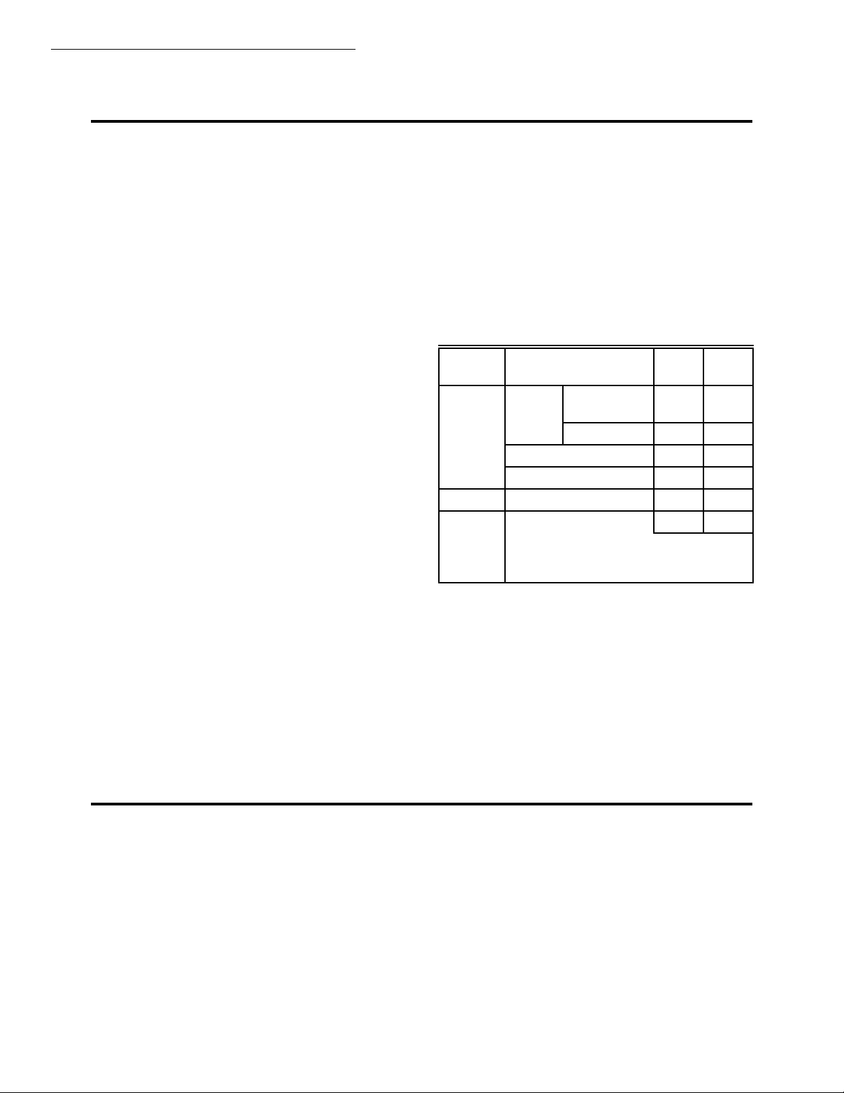
ELECTRICAL RATINGS:
120
Terminal Electrical Load
3 Burner
Motor
4 Ignition
5 Main Valve (Pilot Duty) 125VA 125VA
Alternate Rating: 25 VA pilot duty plus one or
more motorized valves with total rating of 400
VA opening, 200 VA holding.
a
If ignition and motor are connected to terminal 3, terminal
Full Load 5.2A 2.6A
Locked Rotor 31.2A 15.6A
a
Ignition
Pilot Fuel Valve 25VA 25VA
a
Vac
3.0A 1.5A
3.0A 1.5A
240
Vac
4 cannot be used. This prevents overloading relay 1K.
Alarm Contacts: 3.0 A at 24 Vac, or 75 VA pilot duty at
120 Vac in suitable wiring enclosure.
Low Voltage Control Circuit (T-T): 0.17A.
NOTE: Allowable inrush can be up to ten times the pilot duty
rating.
Ordering Information
When purchasing replacement and modernization products from your TRADELINE® wholesaler or distributor, refer to the Tradeline
Catalog or price sheets for complete ordering number, or specify—
1. Order number specify TRADELINE®, if desired. 4. Alarm contacts, if desired.
2. Voltage and frequency. 5. Accessories, if desired.
3. Flame response time.
If you have additional questions, need further information, or would like to comment on our products or services, please write or phone:
1. Your local Home and Building Control Sales Office (please check the white pages of your phone directory).
2. Home and Building Control Customer Logistics
Honeywell Inc., 1885 Douglas Drive North
Minneapolis, Minnesota 55422-4386
In Canada—Honeywell Limited/Honeywell Limitée, 35 Dynamic Drive, Scarborough, Ontario M1V 4Z9. International Sales and
Service Offices in all principal cities of the world. Manufacturing in Australia, Canada, Finland, France, Germany, Japan, Mexico,
Netherlands, Spain, Taiwan, United Kingdom, U.S.A.
60-2035—9 2
Page 3
RA890G
SPECIFICATIONS • INSTALLATION
EXAMPLE: Pilot duty rating = 25 VA.
At 120V, running current is 25 ÷ 20 = 0.21A.
Maximum allowable inrush is10 times 0.21 = 2.1A.
UNDERWRITERS LABORATORIES INC LISTED: 120V
models only: File no. MP268, Guide no. MCCZ.
NOTE:All devices meeting UL component recognition
bear the following symbol:
®
Canadian Standards Associated Certified: 120 V models
only: File no. LR9S329
Factory Mutual Approved: Report no. 22013.
CAUTION
Ultraviolet sensing tubes have a life expectancy
of 40,000 hours of continuous use within the
ambient temperature and voltage ratings. Worn
out ultraviolet sensing tubes result in failure of the
sensing tube to properly discriminate between
flame conditions.
Systems using the RA890G with the C7027,
C7035 and C7044 Flame Detectors should only be
used on burners that cycle On and Off at least once
every 24 hours. Appliances with burners that remain on for 24 hours continuously or longer should
use the C7012E Flame Detector with the R7247C
Amplifier or the C7076A Flame Detector with the
R7476A Amplifier as the ultraviolet flame detection system.
WHEN INSTALLING THIS PRODUCT…
1. Read these instructions carefully. Failure to follow
them could damage the product or cause a hazardous
condition.
2. Check the ratings given in the instructions and on the
product to make sure the product is suitable for your
application.
3. Installer must be a trained, experienced flame safequard
control technician.
4. After installation is complete, check out product operation as provided in these instructions.
American Gas Association Design Certified For -20°F
(-29°C). Certificate no. 20-6b.
ACCESSORIES:
Models with 15 second safety switch: -20F (-29°C).
W136A Microammeter.
123514B Flame Simulator.
196146 Meter Connector Plug.
FSP1535 Test Panel: For operational check of the
RA890E,F,G,H,J or the R4795.
118702E Remote Reset Cover Assembly.
202471A Cover Assembly with reset button.
Installation
Follow the burner manufacturer instructions when sup-
plied; otherwise, proceed as follows.
LOCATION
Temperature
Install the RA890G where the surrounding temperatures
remain within the ambient Operating Temperature Ratings
listed in the SPECIFICATIONS section.
Humidity
Install the RA890G where the relative humidity never
reaches the saturation point. Condensation of moisture on
the RA890G may cause enough leakage to short the flame
signal to ground and prevent the burner from starting.
Vibration
Do not install the RA890G where it could be subject to
excessive vibration. Vibration shortens the life of the electronic components.
Weather
The RA890G is not designed to be weathertight. If it is
installed outdoors, use a suitable weathertight enclosure.
MOUNT SUBBASE
Locate subbase where ambient temperature is within the
specified rating.
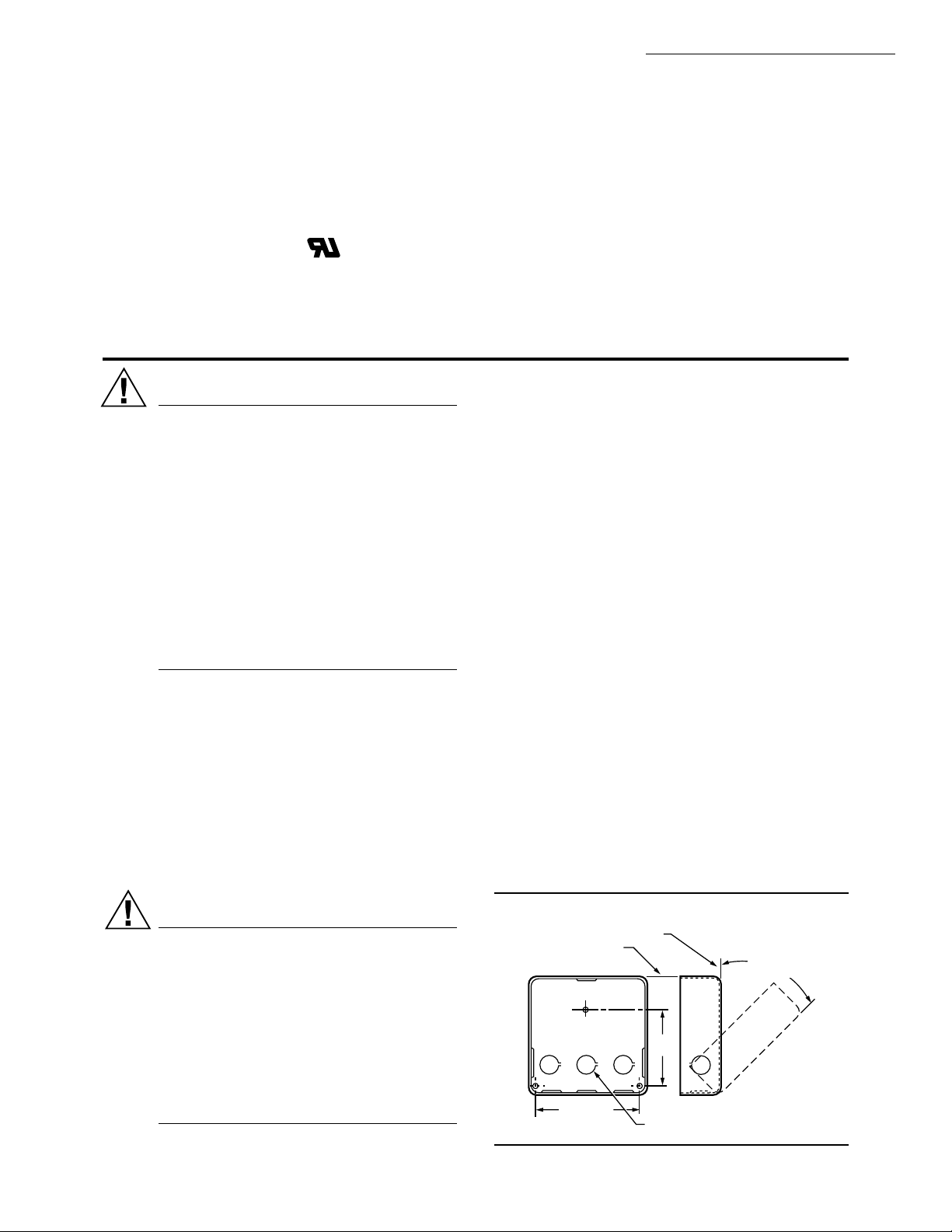
Mount the subbase so that the top and bottom are hori-
zontal and the back is vertical. The subbase may lean
backward as much as 45 degrees if necessary. See Fig. 1.
CAUTION
1. Disconnect power supply before beginning installation to prevent electrical shock and equipment damage. All wiring must comply with applicable local electrical codes, ordinances, and
regulations.
2. Limits must be rated to carry and break current to
the ignition transformer, pilot valve (or first stage
oil valve), and main fuel valve(s) simultaneously.
3. All external timers must be Listed or Component
Recognized by authorities that have jurisdiction
for the specific purposes for which they are used.
Fig. 1—Mounting Subbase. in in. (mm)
HORIZONTAL
4-1/8 (104.8)
VERTICAL
2-7/8
(73.0)
KNOCKOUTS (9) FOR
1/2 IN. (13) CONDUIT
45 DEGREES
MAXIMUM LEAN
M8681
3 60-2035—9
Page 4
RA890G
M8718
L1
(HOT)
L2
1
2
3
4
3
3
2
4
4
1
FOR INTERMITTENT IGNITION, CONNECT TO TERMINAL 3.
ALARM TERMINALS OPTIONAL. IF LINE VOLTAGE ALARM IS USED.
RA890G MUST BE MOUNTED IN SUITABLE ENCLOSURE. ALARM
TERMINALS ARE ENERGIZED THROUGH THE RA890 SAFETY SWITCH.
ALARM IS NOT SOUNDED UNTIL THE SAFETY SWITCH TRIPS OUT.
PROVIDE DISCONNECT MEANS AND OVERLOAD PROTECTION
AS REQUIRED.
MAY USE LINE OR LOW VOLTAGE CONTROLLER. IF LINE VOLTAGE
CONTROLLER IS USED, CONNECT IT BETWEEN THE LIMIT CONTROL
AND TERMINAL 6. JUMPER T-T.
LINE VOLTAGE
CONTROLLER
MAIN GAS
VALVE
IGNITION
TRANSFORMER
PILOT
GAS VALVE
LOW VOLTAGE
CONTROLLER
BLUE
WHITE
6
T
T
F
G2
2
1
3
4
5
DISCONNECT
SWITCH
LINE OR
LOW VOLTAGE
NO ALARM
NC NO COM
USE TERMINALS
NC AND C FOR
NORMALLY
CLOSED ALARM
INDICATOR OR
INTERBLOCK
CIRCUIT IF
DESIRED.
LINE OR LOW VOLTAGE
ALARM POWER SUPPLY
POWER
SUPPLY
RA890G
MANUAL OR AUTO RESET
LOCKOUT LIMIT CONTROL
INSTALLATION
WIRING THE SUBBASE
IMPORTANT: When connecting wire to screw terminal of
terminal strip, wrap wire at least 3/4 of distance
around screw without overlapping. With appropriately sized screwdriver, tighten screw until wire is
snugly in contact with underside of screw and contact
plate. Tighten screw additional one-half turn. Do not
use push-type ratchet screwdriver.
YES NO NO NO NO
1. All wiring must comply with applicable electrical
codes, ordinances, and regulations. Use NEC Class 1 wiring.
2. For normal installations, use moisture-resistant
No. 14 wire (rated for 167°F (75°C) or higher required by
Underwriters Laboratories Inc).
3. For high temperature installations, use moisture-re-
sistant No. 14 wire selected for a temperature rating above
the maximum operating temperature for all but the ignition
and flame detector F leadwires.
a. For the ignition, use Honeywell Specification no.
R1061012 Ignition Cable or equivalent. (This wire is
rated at 350°F (175°C) for continuous duty, and up to
500°F (260°C) for intermittent use. It was tested to
25,000 volts.)
b. For the flame detector F leadwire, use Honeywell
Specification no. R1298020 or equivalent. (This wire
is rated up to 400°F (205°C) for continuous duty. It is
tested for operation up to 600 volts and breakdown up
to 7500 volts.)
4. For ignition installations in a contaminating environ-
ment, use Honeywell Specification no. R1239001 High
Tension Ignition Cable or equivalent. This wire is very
resistant to severe conditions of oil, heat, and corona, and is
tested to withstand high voltages up to 25,000V rms in a salt
bath for one minute without breakdown. It is rated at 200°F
(93°C) for continuous duty, and up to 350°F (175°C) for
intermittent use.
IMPORTANT: Do not run high voltage ignition trans-
5. Refer to Fig. 2 and 3 for typical field wiring connections. Follow the burner manufacturer’s wiring diagram if
former wires in the same conduit with the flame
detector wiring.
provided.
60-2035—9 4
Fig. 2—Gas system with interrupted ignition.
M8717
APPLICATIONS
Either a line or low voltage controller can be used. If a
line voltage controller is used, connect it between the limit
control and terminal 6, and jumper T-T.
Refer to the appropriate flame detector instructions when
paralleling two flame detectors.
IMPORTANT: The C7027, C7035 and C7044 Flame De-
tector leads are color coded blue and white. The blue
lead must be connected to the F terminal and the white
lead to the G terminal. The circuit is dc and the UV
tube is polarity sensitive. Reversing the leads, even
momentarily, can damage or destroy the UV tube.
All wiring must be NEC Class 1 and conform to local
electrical codes, ordinances, and regulations. If the leadwires
are not long enough to reach the flame safeguard control,
splices must be made in a junction box.
Page 5

RA890G
INSTALLATION • OPERATION AND CHECKOUT
Fig. 3—Oil-Fired system with interrupted
ignition.
MANUAL OR AUTO RESET
LOCKOUT LIMIT CONTROL
LINE VOLTAGE
CONTROLLER
RA890G
6
4
LOW VOLTAGE
CONTROLLER
FOR INTERMITTENT IGNITION,
1
CONNECT TO TERMINAL 3.
ALARM TERMINALS OPTIONAL.
2
PROVIDE DISCONNECT MEANS AND OVERLOAD
3
PROTECTION AS REQUIRED.
MAY USE LINE OR LOW VOLTAGE CONTROLLER. IF LINE VOLTAGE
4
CONTROLLER IS USED, CONNECT IT BETWEEN THE LIMIT CONTROL
AND TERMINAL 6. JUMPER T-T.
T
T
BLUE
F
WHITE
G2
2
5
4
3
1
2
4
SECOND STAGE
OIL VALVE
(IF USED)
IGNITION
TRANSFORMER
PILOT
GAS VALVE
DISCONNECT
SWITCH
1
OIL
VALVE
L2
POWER
SUPPLY
M8719
L1
(HOT)
3
The use of manual reset limits is desirable with the
RA890G to prevent the system from cycling off the high
limit and to assure that the condition that causes the limitation is detected as soon as possible.
MOUNT RA890G
Check that the power is Off.
Remove relay cover and position the RA890G over the
Q270A Universal Mounting Base. See Fig. 4. Start all ten
mounting screws and tighten uniformly. These screws complete electrical circuits and hold the RA890G to the subbase.
As shipped from the factory, the RA890G is suitable for
use with interrupted or intermittent systems.
Fig. 4—RA890G and Q270A Subbase.
TERMINAL
BLOCKS
Q270A
UNIVERSAL
SUBBASE
FLAME
RELAY (2K)
LOAD
RELAY (1K)
RA890G
BASE
FLAME
CURRENT
TEST JACK
SAFETY
SWITCH
RA890G
COVER
RESET
PUSHBUTTON
THUMBSCREW
TRANSFORMER TR2
TRANSFORMER TR1
M8720
CAUTION
1. Use extreme care while testing the RA890G;
line voltage is present on some terminals and
contacts when power is On.
2. Disconnect power supply before removing
cover, removing RA890G from subbase, or
reinstalling RA890G onto subbase.
PRELIMINARY CHECKS
Before placing the system in operation, complete the
following preliminary checks:
1. Check wiring. Use a meter to check the continuity of
all circuits.
2. Check flame detector installation.
3. Check burner adjustments.
4. Thoroughly purge gas piping.
5. Reset the safety switch by pushing in and then releas-
ing the purple safety switch button.
Operation And Checkout
NORMAL OPERATION SUMMARY
Refer to Fig. 5 for the internal schematic of the control.
1. Call for heat—Load relay pulls in after a slight delay
(flame relay must be out), ignition starts, pilot valve or
burner motor is powered. Safety switch heats. A safety
shutdown occurs if a flame or flame simulating condition is
detected at startup.
2. Flame proved—Flame relay pulls in, safety switch
heater is de-energized, main valve is powered, ignition is cut
off (if used for interrupted ignition).
3. Call for heat satisfied—Load relay drops out, fuel
valves close, burner motor stops, and flame relay drops out.
NOTE: The pull-in of the load relay is delayed by a ther-
mistor with a nominal delay time of 3 to 5 seconds. The
thermistor is affected by ambient temperature. The delay
time may be as little as two seconds when the ambient
temperature is high, or as long as 30 seconds when the
ambient temperature is low. As the thermistor warms up,
the 1K relay may hum slightly before it pulls in. This is
normal.
5 60-2035—9
Page 6

RA890G
OPERATION AND CHECKOUT
IMPORTANT: If limit control opens, ignition and fuel
valves are de-energized, but safety switch lockout will
not occur. When normal conditions are restored and
the limit closes, the RA890G recycles.
least once a month (or more often) while the system is in
operation. This prevents shutdowns due to poor flame signal.
Use a W136A Microammeter, or equivalent, and read the
flame signal while the burner is running. Insert a 196146 Test
Cable, wired color-to-color to the W136A leadwires, into the
CHECKOUT REQUIRED
Before the installation is complete, satisfactorily complete all checkout tests indicated below. Repeat these tests
after any adjustments are made to the system.
Flame Current Check (all installations).
Pilot Turndown Test (all installations that required proof
of pilot before main fuel valve is opened).
Ignition Spark Response Test (all installations).
Safe Shutdown Checks—Flame failure, power failure,
limit action (all installations).
test jack on the RA890G. See Fig. 6.
When reading the flame current, assure that the following
criteria are met:
1. The flame current is steady; meter does not vary more
than a needle width.
2. The flame current is at least 1.5 microamperes for an
ultraviolet type detector such as used with the RA890G.
If a satisfactory reading is not obtained, check the power
source for the proper line voltage, and the flame size and the
detector for proper sensing.
Directions for obtaining a steady current reading are
FLAME CURRENT CHECK
The Flame Current Check is the best indicator of proper
included in the instructions packed with the C7027, C7035
or C7044 Ultraviolet Flame Detector.
flame detector application. Perform the check at the time of
installation, at any time service is done on the system, and at
NOTE: Flame current cannot be measured by putting a
microammeter in the F lead.
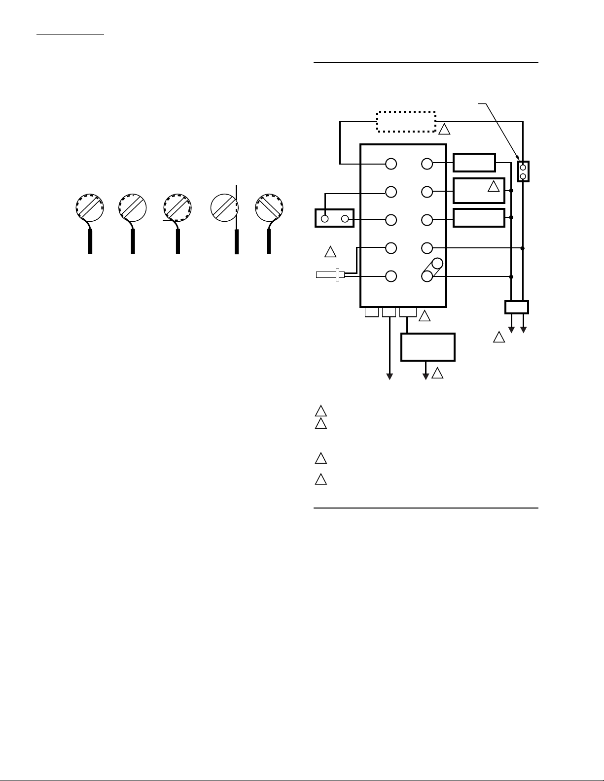
Fig. 5—Internal Schematic of RA890G (Typical External Connections Included).
LINE VOLTAGE
CONTROLLER
RA890G
3
LIMIT
CONTROLLER
2
6
THERMISTOR
T
3
T
LOW VOLTAGE
CONTROLLER
BLUE
TO FLAME
DETECTOR
5
1
2
3
4
5
6
WHITE
PROVIDE DISCONNECT MEANS AND OVERLOAD PROTECTION AS REQUIRED.
RA890G TERMINALS 1 AND 6 MUST BE POWERED.
MAY USE LINE OR LOW VOLTAGE CONTROLLER. IF LINE VOLTAGE CONTROLLER IS USED, CONNECT IT BETWEEN THE LIMIT
CONTROLLER NAD TERMINAL 6. JUMPER T-T.
FOR INTERMITTENT IGNITION CONNECT TO TERMINAL 3.
MINIPEEPER DETECTORS ARE POLARITY SENSITIVE—BLUE LEAD MUST BE CONNECTED TO THE F TERMINAL;
WHITE LEAD CONNECTED TO THE G TERMINAL.
ALL WIRING MUST BE NEC CLASS 1.
F
G
2K3
1K2
1K
(LOAD RELAY)
1K3
2K (FLAME RELAY)
TEST
JACK
SAFETY
SWITCH
HEATER
2K4
1K4
ELECTRONIC
AMPLIFIER
NETWORK
SAFETY
SWITCH
1K1
TR1
TR2
2K2
5
2K1
4
3
2
1
2
MAIN GAS VALVE
OR SECOND STAGE
OIL VALVE (IF USED)
INTERRUPTED
IGNITION
PILOT GAS VALVE,
OR BURNER MOTOR
AND DELAYED OIL
VALVE; INTERMITENT
IGNITION
MASTER
SWITCH
4
POWER
SUPPLY
6
L1
L2
(HOT)
1
M8721
60-2035—9 6
Page 7

RA890G
OPERATION AND CHECKOUT
Fig. 6—Flame current check.
W136A
196146 METER
BLACK
RED
CONNECTOR
PLUG (SUPPLIED
WITH W136)
BLACK
RED
RA890
FLAME
CURRENT
TEST JACK
M8716
PILOT TURNDOWN TEST
CAUTION
The pilot turndown test should be performed only
by qualified personnel, and the instructions should
be followed carefully.
On systems that prove a pilot before the main fuel valve
can be opened, perform a pilot turndown test to prove that the
main burner can be lighted by the smallest pilot that will hold
in the flame relay. Perform a flame current check before and
after the pilot turndown test.
1. Open the main power switch.
2. Shut off the fuel supply to the main burner only by
closing the manual main burner shutoff cock. Do not shut off
the fuel supply to the pilot valve.
3. Restore power to the relay.
4. Start the system by raising the setpoint of the controller (or pressing the START button). The pilot will light and
pull in the flame relay.
5. Reduce the size of the pilot flame to the turndown
condition by slowly closing the manual valve on the pilot gas
line. At the turndown condition, the pilot will be small
enough to just barely hold in the flame relay (2K).
a. Turn down the pilot until relay 2K drops out.
b. Turn the pilot back up slowly just until relay 2K pulls
back in.
c. Again turn the pilot down slightly, but not enough so
the relay drops out.
If the relay drops out again, simply turn up the pilot and
try again. The closer the pilot is to the dropout condition, the
more conclusive the test will be.
6. Check that the pilot is lit and relay 2K is pulled in.
7. Open the manual main burner shutoff cock. Main
flame should light smoothly within one second. If the burner
does not light within one second, close the shutoff cock and
shut off power to the relay. Proceed to step 9.
8. If the burner lights, repeat step 7 two or three times to
verify smooth lightoff.
9. If the lightoff is unsatisfactory, readjust the flame
detector to require a larger pilot flame to hold in the flame
relay. This usually requires resighting the detector farther
out on the axis of the pilot flame.
CAUTION
If the pilot needs to be adjusted and rechecked,
allow five minutes for the purge of unburned gases
in the firebox before proceeding to the next step.
10. Repeat the entire turndown test until the flame is
established promptly in step 7.
11. Turn up the pilot to full flame at the completion of the
test. Perform a flame current check before leaving the job.
IGNITION SPARK RESPONSE TEST
The flame detection system should not respond to the
ignition spark (no meter movement). To determine flame
detector sensitivity to ignition spark, perform the following
steps:
1. Shut off pilot and main fuel manual valves.
2. Connect a W136 Microammeter and 196146 Test
Cable into the test jack on the RA890G. (See Flame Current
check procedure section.)
3. Raise the controller setpoint. This should energize the
ignition transformer and produce an ignition spark.
4. The W136 Meter should not indicate a signal present.
5. If the meter indicates UV is being detected, resight the
flame detector until the UV signal is eliminated. It may be
necessary to construct a barrier to block the ignition spark
from the detector view. Continue adjusting until the ignition
spark flame signal is less than one-fourth microampere.
NOTE: The Honeywell Q624A Solid State Spark Generator
prevents detection of ignition spark when properly applied with flame detection systems using C7027, C7035,
or C7044 Minipeeper Ultraviolet Flame Detectors. The
Q624A is for use only with gas pilots.
SAFE SHUTDOWN CHECKS LIMIT ACTION
With the burner operating, lower the high limit setting to
simulate an overheated boiler or furnace. Normal shutdown
should occur. Restore the normal limit setting; the burner
should restart.
FLAME FAILURE RESPONSE TEST
With the burner operating for a period of five minutes,
close the manual fuel valves to simulate a flame failure. The
W136 Meter reading should drop to zero within the flame
response timing of the flame safeguard relay (0.8 to 3 seconds nominal). This action should be followed by safety
switch lockout (15 seconds nominal). After the safety switch
cools, open the manual valves. The burner should restart
when the safety switch is reset.
If the meter reading does not drop to zero within the
allowed time, replace the UV detector and repeat the test.
IMPORTANT: Repeat ALL required checkout tests after
all adjustments are complete. ALL tests must be satisfied with the flame detector in its FINAL position.
7 60-2035—9
Page 8

RA890G
OPERATION AND CHECKOUT • SERVICE
POWER FAILURE
With the burner operating, open and then immediately
close the line switch to simulate a power failure. Burner
should shut down. After a short delay for component check,
burner should restart and operate normally.
FLAME DURING START
The RA90G should shut down on safety during start-up if
a flame or flame simulating condition is detected. Insert
123514B flame simulator into the test jack. Start the system
by raising the controller setpoint or pressing the start button.
CAUTION
1. Only a trained, experienced, flame safeguard
control technician should attempt to service or
repair heating equipment or controls.
2. Under certain conditions, a capacitor between
terminals F and G within RA890G can remain
charged even after the power is disconnected
and the device is removed from the mounting
base. TO AVOID THE HAZARD OF ELECTRICAL SHOCK, ALWAYS USE A SCREWDRIVER WITH AN INSULATED HANDLE
AND AVOID TOUCHING THE F AND G
TERMINALS.
3. Never manually push in the RA890 Relays.
Hold the simulator on terminal F; the flame relay should pull
in and system should lock out within the safety switch
timing. Remove the simulator and reset the safety switch
after it cools.
NOTE: At the completion of all Checkout tests, make sure
that the RA890 is not on safety lockout, the pilot is turned
up to its normal level, and all limit settings are correct.
Operate the system through one normal cycle before
leaving the installation.
Service
2. Inspect and clean the detector and any viewing windows as often as required by soot accumulation and heat
conditions at the detector.
3. Perform a Flame Current Check at least monthly, and
more often when a shutdown may be costly.
4. Clean contacts only when required by failure to operate properly.
CONTACT CLEANING
CAUTION
Open the master switch before removing the relay
over or before cleaning contacts. Line voltage may
be present on most contacts when power is on.
GENERAL
1. Repeat all checks required in the Checkout section
when replacing any system component, or when relighting
or restoring power to the system after an extended shutdown
period.
2. The captive mounting screws carry current; always
disconnect power before loosening or tightening the mounting screws.
3. On each service call, check the controller for the
approximately correct calibration and differential; assure
that it is mounted securely (see controller instructions).
4. Never use oil on any part of the RA890G.
5. When cleaning the burner, clean the flame detector
lens.
6. DO NOT MANUALLY PUSH IN THE RA890 RE-
LAYS. This may damage the relays and it is an unsafe
practice because it overrides the protective features of the
relay. Clean relay contacts only as instructed below.
PERIODIC MAINTENANCE
The specific maintenance schedule setup depends on
several factors including type of equipment being controlled,
operating conditions (dirt and heat especially), cost of a
nuisance shutdown, etc. Include the following in any maintenance program:
1. Perform a Flame Failure Check and Pilot Turndown
Test whenever the burner is serviced, and at least annually.
Field cleaning of relay or timer contacts is not recommended. If they must be cleaned, use only Honeywell
pressurized Contact Cleaner part no. 132569. Honeywell’s
chemical analysis laboratory recommends only this cleaner.
Directions for using the cleaner are printed on the can.
IMPORTANT:
1. Do not clean contacts unless absolutely necessary.
2. Use only Honeywell Contact Cleaner part no. 132569.
Do not use any other type of contact cleaner.
3. Use extreme care to avoid bending the contacts or
changing the specifications or configuration in any
way.
4. Do not use abrasive material to clean contacts.
5. Do not use hard paper such as a business card to clean
the contacts.
Do not use other types of contact cleaners. Honeywell’s
chemical analysis laboratory tested other pressurized type
contact cleaners but did not approve them for these reasons:
1. The solvents could deteriorate plastic parts and wire
insulation.
2. The cleaners have an oily residue that collects dust and
dirt. The residue breaks down to form various carbonaceous
products. Either result causes early contact failure.
Do not use an abrasive (burnishing tool, sandpaper, stick,
file, etc.) to clean contacts because it can cause early contact
failure for these reasons:
60-2035—9 8
Page 9

RA890G
SERVICE • TROUBLESHOOTING
1. Some relay and time contacts are plated with gold for
increased reliability. Burnishing can quickly remove the
plating.
2. The radii or points of the contacts are designed with
specific shapes to best serve the intended functions of the
contacts. Burnishing can rapidly alter contact configurations.
CAUTION
1. Use extreme care while troubleshooting the
RA890G; line voltage is present on some terminals and contacts when power is on.
2. Disconnect the power supply before removing
the cover, cleaning contacts, removing the
RA890G from the subbase, or reinstalling the
RA890G on the subbase.
When trouble occurs in the heating system and its cause is
not immediately apparent, the serviceman can apply the
following step-by-step checkout to locate the cause of most
problems.
TEST STANDBY OPERATION
1. Set controller not to call for heat (decrease setpoint).
2. Reset the safety switch by pushing in and then releas-
ing the purple safety switch reset button.
3. Close the line switch.
4. Check for line voltage between terminals 6 and 2, and
between 1 and 2. (Voltage will be zero at terminal 6 if a line
voltage controller is used; check for line voltage when
controller is set to call for heat.)
a. Voltage must be within +10 to -15 percent of the rated
voltage.
b. If voltage is zero, check the power supply line for
blown fuses, open circuit, or open disconnect switch.
Check limit contacts for continuity.
5. Check position of flame relay. (If a line voltage controller is used, observe the action of the flame relay on a call
for heat.)
a. If the flame relay is out, proceed to step 6.
b. If the flame relay is pulled in, check for a flame
simulating condition.
1) Insert 123514B Flame Simulator Plug into test
jack; touch the other end to the F terminal of the
RA890G.
2) If flame relay holds in, replace the RA890.
3) If flame relay drops out, trouble is in the flame
detector or external circuit. Replace the detector.
TEST STARTING OPERATION
6. Set controller to call for heat (increase setpoint).
7. Observe load relay for pull-in.
a. Load relay pulls in to light pilot and start burner;
proceed to step 11.
b. Load relay does not pull in; proceed to step 8.
3. Using an abrasive loosens fine particles of the contact
material that adhere to the surface of the contact and increase
its resistance.
4. Contact specifications (contact pressures, pressback,
and gaps) are carefully controlled during manufacturing to
assure maximum contact life. Burnishing can easily change
these specifications.
Troubleshooting
c. Load relay pulls in but does not light or burner does not
start; proceed to step 10.
8. Check line voltage controller, if used, and check the
limit; if the load relay does not pull in, check again for power
at terminal 6 with the controller calling for heat. If there is
power at terminal 6 and a line voltage controller is used,
clean all relay contacts. Replace the RA890 if the relay still
does not pull in. If a low voltage controller is used, proceed
to step 9.
9. Check the low voltage controller, if used, by jumping
T-T.
a. Load relay pulls in with T-T jumpered; check control-
ler and external circuit.
b. Load relay does not pull in with T-T jumpered; clean
all relay contacts. Replace the RA890 if the load relay
still does not pull in.
10. If the load relay pulls in but the pilot will not light or
the burner will not start, check voltage at terminals 3-2 or 4-2.
a. If no voltage at terminals 3-2 or 4-2; clean the relay
contacts. Replace the RA890 if trouble cannot be
corrected.
b. If normal line voltage at terminals 3-2 or 4-2, check
external burner, ignition, and valve circuits. Check
wiring, burner adjustment, ignition systems including
electrode spacing and location, oil quality, character
and efficiency of oil atomization, fuel supply pressure,
flame pattern, flame character and quality, pilot location with respect to main burner, flame detector, or
other conditions that may delay lightoff.
TESTING FLAME DETECTING FUNCTION
11. Observe the flame relay (right relay) for pull-in when
flame is established.
a. Flame relay pulls in; proceed to step 13.
b. Flame relay does not pull in; proceed to step 12.
12. Check the flame relay with a 123514B Flame Simulator, if available (follow the instructions with the simulator),
or check the following:
a. Perform a Flame Current Check (see Flame Current
Check section).
b. If the current is satisfactory, replace the RA890.
c. If the current is not satisfactory, consult the instruc-
tions packed with the flame detector.
OBSERVE SEQUENCING OPERATION
13. Observe the second stage oil valve or main gas valve
for opening when flame relay pulls in.
a. If valve does not open, check for line voltage at
terminals 2-5.
9 60-2035—9
Page 10

RA890G
TROUBLESHOOTING
1) Normal voltage—check valve and valve circuit.
2) Zero voltage—clean relay contacts. Replace the
RA890 if this does not correct problem.
14. Observe ignition for cutoff when flame relay pulls in if
connected to terminal 4.
a. If ignition stays on and wiring checks out, replace the
RA890.
MISCELLANEOUS PROBLEMS
Relay Chatter
Load relay chatter may result from extreme low voltage
(notify power company) or from a loose connection (tighten).
Flame relay chatter may result from improper combustion (adjust burner), or soot or carbon on flame detector
(clean and correct the cause).
REPEATED LOCKOUTS OR CONTROL
FAILURES
The most common causes of repeated failure of this
control or flame detector or of repeated lockouts are:
a. High ambient temperatures—over 125°F (52°C).
b. Supply voltage variation greater than +10 to -15 percent.
c. Electrical overloading of the contacts.
d. Marginal flame current.
e. Frequent cycling with high ambient temperatures.
60-2035—9 10
Page 11

11 60-2035—9
Page 12

Home and Building Control Home and Building Control Helping You Control Your World
Honeywell Inc. Honeywell Limited—Honeywell Limitée
1985 Douglas Drive North 740 Ellesmere Road
Golden Valley, MN 55422 Scarborough, Ontario
M1P 2V9
60-2035—9 12
Printed in U.S.A. www.honeywell.com/bbc
 Loading...