

Honeywell RA890F Quick Manual

The RA890F Protectorelay™ Primary Control
is a nonprogramming, amplifying relay that provides solid state electronic flame safeguard protection for industrial and commercial gas, oil, or
combination gas-oil burners.
RA890F
Flame Safeguard
Primary Control
■ Employs rectification principle of electronic flame
detection using a flame rod, rectifying photocell, or
C7012A,C Ultraviolet Flame Detector.
■ Clipping pilot link jumper wire permits use with
standing pilots.
■ Can directly replace RA890E and mount on same
Q270A Subbase.
■ Solid state circuitry eliminates vacuum tube replace-
ment and increases resistance to vibration. Power
application not required during Off cycle; no tube to
warm up before starting.
■ Push-to-reset safety switch in dust-resistant enclosure.
■ Built-in protection against ignition crossover in flame
rod systems.
■ Does not start if flame-simulating failure occurs in
flame detector circuit.
■ Automatic safety shutdown if flame fails on start, or
if flame not re-established after flame failure.
■ Flame signal current is directly measurable at test
jack.
■ Line or 24 volt, automatic or manual controller can be
used. (Manual controller must open circuit on either
power or flame failure.)
■ Captive mounting screws allow easy mounting and
removal. Thermoplastic mounting base.
■ Optional alarm circuit indicates safety shutdown.
CONTENTS
Specifications .................................................2
Ordering Information..................................... 2
Installation .....................................................4
Operation .......................................................7
Checkout......................................................... 8
Service ..........................................................10
Troubleshooting and Maintenance ..............10
S.Y. • Rev. 11-94 • ©Honeywell Inc. 1994
1 60-2034—7
60-2034-7
RA890F
SPECIFICATIONS • ORDERING INFORMATION
Specifications
TRADELINE® MODELS
TRADELINE® models of this device are available. They
are selected and packaged to provide ease of stocking, ease of
handling, and maximum replacement value. TRADELINE
model specifications are the same as those of the standard
model except as noted below.
TRADELINE® MODELS AVAILABLE:
RA890F for 120V, 50/60 Hz power supply.
RA890F for 240V, 50/60 Hz power supply.
ADDITIONAL FEATURES: TRADELINE® packed with
cross reference label and special cross reference listing.
STANDARD MODELS
MODEL: RA890F Protectorelay™ Primary Control.
ELECTRICAL RATINGS:
Voltage and Frequency: 100V, 120V, 208V, 220V, or
240V, 50/60 Hz. As ordered.
Power Consumption:
60 Hz: 7.0W maximum, 1.7W standby.
50 Hz: 8.5W maximum, 3.0W standby.
VA Ratings:
60 Hz: 13.0 VA maximum, 8.3 VA standby.
50 Hz: 17.0 VA maximum, 13.6 VA standby.
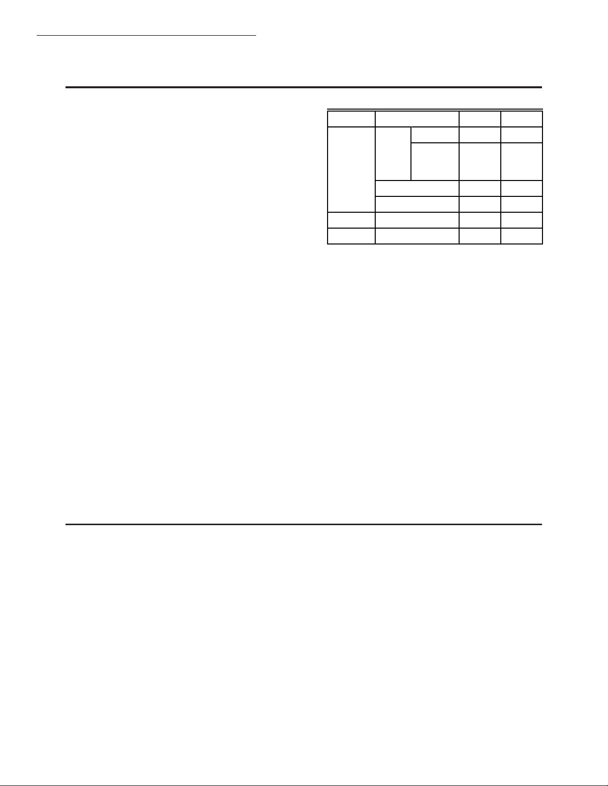
Terminal Ratings:
Terminal Electrical Load 120 Vac 240 Vac
®
3
Burner
Motor
Full Load 5.2A 2.6A
Locked
31.2A 15.6A
Rotor
(inrush)
Ignition
a,b
3.0A 1.5A
Pilot Fuel Valve 25 VA 25 VA
4 Ignition
5 Gas Valve
a
If ignition and motor are connected to terminal 3, termi-
a
b
3.0A 1.5A
125 VA 125 VA
nal 4 cannot be used. This is to prevent overloading
relay 1K.
b
Alternate Rating: 25 VA pilot duty plus one or more
motorized valves with total rating 400 VA opening,
200 VA holding.
Alarm Contacts: 3.0A at 24 Vac or 1.0A at 120 Vac in
suitable wiring enclosure.
Low Voltage Control Circuit (T-T): 0.3A.
Ordering Information
When purchasing replacement and modernization products from your TRADELINE® wholesaler or your distributor, refer to the
TRADELINE® catalog or price sheets for complete ordering number, or specify:
1. Order number (standard or TRADELINE
2. Voltage and frequency.
3. Flame response time.
4. Safety switch timing.
5. Alarm contacts, if desired.
6. Fast thermistor timing if desired.
7. Accessories, if desired.
If you have additional questions, need further information, or would like to comment on our products or services, please write or phone:
1. Your local Honeywell Home and Building Control sales office (check white pages of phone directory).
2. Home and Building Control Customer Logistics
Honeywell Inc., 1985 Douglas Drive North
Minneapolis, Minnesota 55422-4386 (612) 951-1000
In Canada—Honeywell Limited/Honeywell Limitée, 740 Ellesmere Road, Scarborough, Ontario M1P 2V9. International sales and service
offices in all principal cities of the world. Manufacturing in Australia, Canada, Finland, France, Germany, Japan, Mexico, Netherlands, Spain,
Taiwan, United Kingdom, U.S.A.
60-2034—7 2
®
).
RA890F
SPECIFICATIONS
NOTE: Allowable inrush can be up to ten times the pilot
duty rating.
EXAMPLE: Pilot duty rating = 25 VA.
At 120V, running current is 25 = 0.21A.
Maximum allowable inrush is 10 times 0.21 = 2.1A.
Maximum Power Interruption: 12 milliseconds; longer
interruption causes 1K to drop out; burner shuts down.
After a short delay for component check, burner should
restart and operate normally.
FLAME FAILURE RESPONSE TIME: 0.8 seconds or
3 seconds nominal, as ordered. Three second response is
recommended for nonrecycling ignition cutoff service to
prevent nuisance shutdowns.
FLAME DETECTORS: Flame rod, rectifying photocell, or
C7012A,C Ultraviolet Flame Detector.
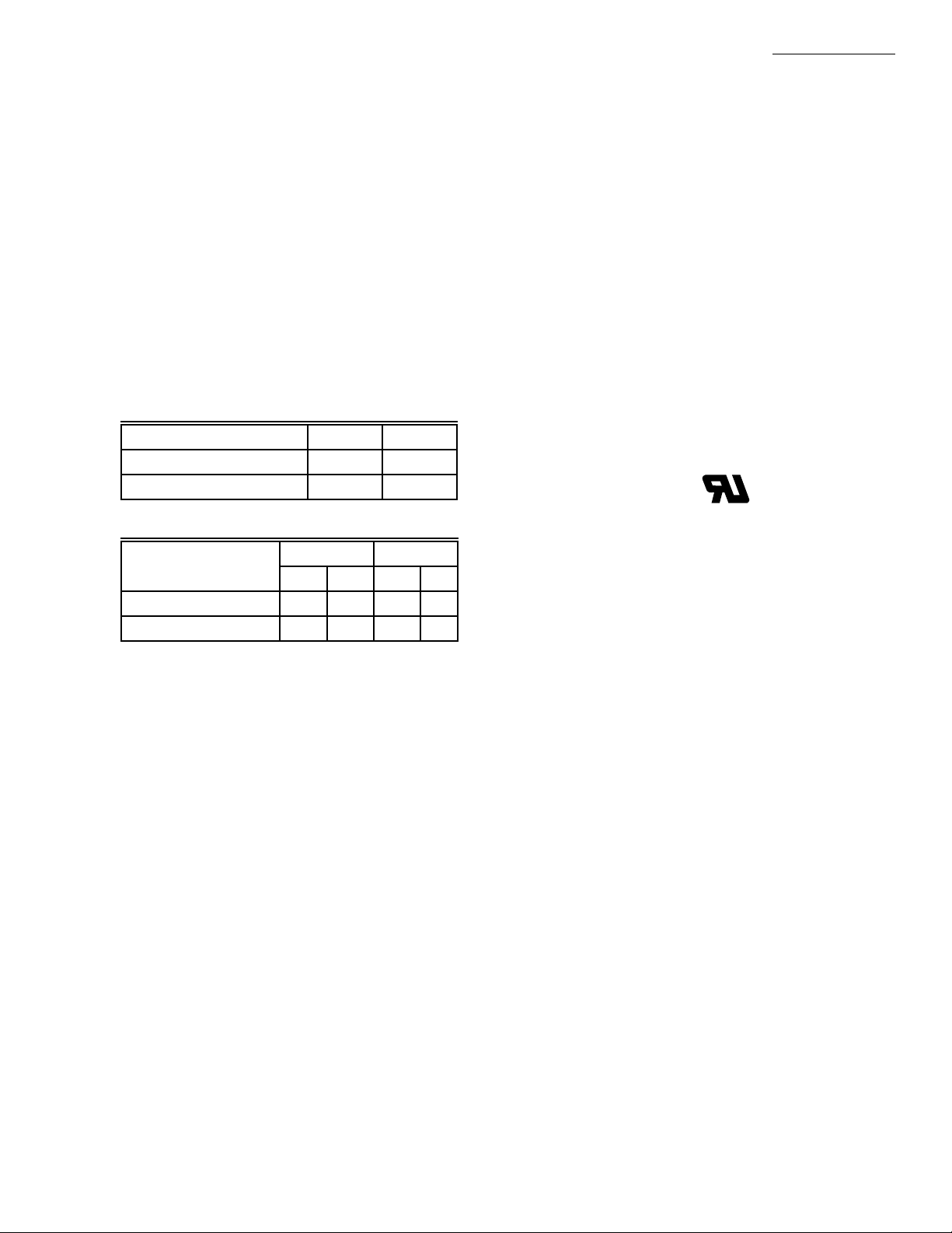
AMBIENT TEMPERATURE RATINGS:
Minimum:
Model °F °C
15 sec safety switch -20 -29
30 sec safety switch +10 -12
Maximum:
50 Hz 60 Hz
Model °F °C °F °C
Without alarm contacts 115 46 125 52
With alarm contacts 105 41 115 46
Models with 30 second safety switch operate safely at
temperatures to -30°F (-34°C) but may encounter difficulty
when resetting a tripped safety switch below the rated
temperature.
SAFETY SWITCH TIMING (LOCKOUT TIME): 15 or
30 seconds as ordered. Timings are proportional with
input voltages and temperatures. For RA890s that are
classified in Underwriters Laboratories Inc gas groups 6
and 6A and oil group 8, the maximum safety switch
timing with voltages ranging from 70 to 110 percent of
rated voltage and with ambients ranging from 32°F (0°C)
to 115°F (66°C) is allowed to be as high as 50 seconds.
FLAME ESTABLISHING PERIOD:
Models with 15 sec Safety Switch: Up to 15 sec.
Models with 30 sec Safety Switch: Up to 30 sec.
RECYCLE TIME: Occurs immediately when flame loss
recognized. See Flame Failure Response Time.
THERMISTOR DELAY OF LOAD RELAY PULL-IN:
4 seconds nominal. Voltage level and ambient temperature affects delay time. Actual delay may be 2 to 30 seconds under ambient temperature extremes. Fast thermistor
model with 1 sec nominal delay time is available when
long delay is a problem. Fast delay model is available
only with the following specifications: 120V, 50/60 Hz,
15 sec safety switch, 0.8 flame response timing, for use
with flame rod detector only.
ALARM CONTACTS (Optional): Isolated spdt contacts.
Male quick-connect terminals (female quick-connects
included). See rating above.
DIMENSIONS: Approximately 5 x 5 x 5 in. (127 x 127 x
127 mm) including subbase.
MOUNTING: On Q270A Universal Mounting Base or-
dered separately.
APPROVALS: Underwriters Laboratories Inc Listed: 120V,
models only; File No. MP268, Guide No. MCCZ.
NOTE: All devices meeting UL components recognition
have the following symbol:
Replacement exchange controls that meet current UL
requirements are identified with the term REMFR’D
following the listing or component recognition mark.
Canadian Standards Association Certified: 120V models
only; File No. LR1620.
Factory Mutual Approved: Report No. 17678, 19417,
and 19784.
American Gas Association Design Certified for -20°F
(-29°C): Certificate No. 20-AL.
ACCESSORIES:
W136A Microammeter (includes 196146 Plug).
121708 Flame Simulator.
196146 Meter Connector Plug.
FSP1535 Tester for operational check of all RA890s.
Q270A1024 Mounting Subbase serves as junction box to
connect to external circuits. Q270A contains terminal
blocks with coded terminals and screws.
R482F Relay to provide safe-start checks when RA890F
is used in special standing pilot applications.
13891L Cover Assembly with reset button. 120 Vac model.
118702E Remote Reset Cover.
3 60-2034—7
RA890F
INSTALLATION
Installation
WHEN INSTALLING THIS PRODUCT…
1. Read these instructions carefully. Failure to follow them could damage the product or cause a hazardous
condition.
2. Check the ratings given in the instructions and on
the product to make sure the product is suitable for your
application.
3. Installer must be a trained, experienced, flame safeguard control technician.
4. After installation is complete, check out product operation as provided in these instructions.
CA UTION
1. Disconnect power supply before beginning installation to prevent electrical shock and equipment damage.
2. All external timers must be Listed or Component
Recognized by authorities that have jurisdiction
for the specific purpose for which they are used.
Refer to Fig. 3 and 4 for typical field wiring connections.
See Fig. 5 for schematic diagram. Follow the burner manufacturer’s instructions if supplied. Otherwise proceed as
follows.
LOCATION
Temperature
Install the RA890F where the surrounding temperatures
remain within the Ambient Operating Temperature Ratings
listed in the SPECIFICATIONS section.
Humidity
Install the RA890F where the relative humidity never
reaches the saturation point. Condensation of moisture on
the RA890F may cause enough leakage to short the flame
signal to ground and prevent the burner from starting.
Vibration
Do not install the RA890F where it could be subject to
excessive vibration. Vibration shortens the life of the electronic and mechanical components.
Weather
The RA890F is not designed to be weathertight. If it is
installed outdoors, use a suitable weathertight enclosure.
Mount Subbase
Locate the subbase where ambient temperature is within
the specified rating.
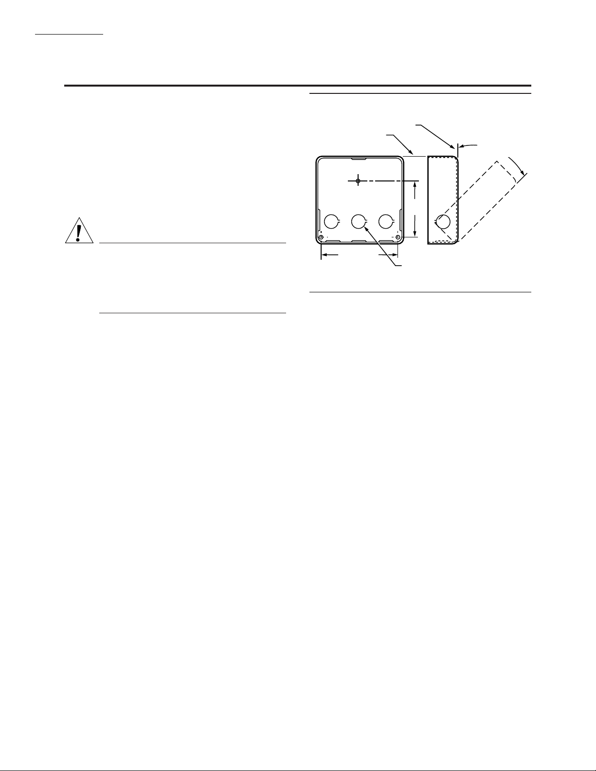
Mount the subbase so the top and bottom are horizontal
and the back is vertical. The subbase can lean backward as
much as 45 degrees when necessary. See Fig. 1.
Fig. 1—Mounting subbase in in. (mm).
VERTICAL
HORIZONTAL
45 DEGREES
MAXIMUM LEAN
2-7/8
(73.0)
4-1/8 (104.8)
KNOCKOUTS (9) FOR
1/2 IN. (13) CONDUIT
M8681
WIRE SUBBASE
1. Disconnect power supply (see Fig. 2) before making
wiring connections to avoid electrical shock and equipment
damage. Assure all wiring complies with applicable electrical codes, ordinances, and regulations. Use NEC Class 1
(line voltage) wiring.
When wiring the Q270A Universal Mounting Base for
use with the RA890F, use the terminal designations 6, T and
T (printed in white).
2A. For normal installations, use moisture-resistant
No. 14 wire suitable for at least 167°F (75°C). For
high temperature installations, use moisture-resistant No. 14 wire selected for a temperature rating
above the maximum operating temperature for all
but the ignition and flame detector F leadwires.
a. For the ignition, use Honeywell Specification
no. R1061012 Ignition Cable or equivalent. (This
wire is rated at 350°F (175°C) for continuous
duty, and up to 500°F (260°C) for intermittent
use. It was tested to 25,000V.)
b. For the flame detector F leadwire, use Honey well
Specification no. R1298020 or equivalent. (This
wire is rated up to 400°F (205°C) for continuous
duty. It was tested for operation up to 600V and
breakdown up to 7500V.)
2B. For ignition installations in a contaminating environ-
ment, use Honeywell Specification no. R1239001
High Tension Ignition Cable or equivalent. This
wire is very resistant to severe conditions of oil, heat,
and corona, and is tested to withstand high voltages
up to 25,000V rms in a salt bath for one minute
without breakdown. It is rated at 200°F (93°C) for
continuous duty, and up to 350°F (175°C) for intermittent use.
60-2034—7 4
 Loading...