

Page 1

RA889A
Switching Relay
PRODUCT DATA
FEATURES
• High load switching capability.
• Troubleshooting LED.
• Push-to-test button.
• Replaceable transformer fuse.
• Long-life DC relay drive control technology.
• Relay for use with external 24 Vac or 24 Vdc supply,
with line-voltage control, or with internal 24V
transformer supply.
• One model replaces many Honeywell models. (See
Table 1 Replacement Cross Reference.)
APPLICATION
The RA889A Switching Rel ay provides intermedi ate switching
of line- and low-voltage devices from a line- or low-voltage
controller and is typically applied in hydronic heating systems.
Contents
Application ........................................................................ 1
Features ........................................................................... 1
Specifications ................................................................... 2
Ordering Information ........................................................ 2
Installation ........................................................................ 3
Mounting ........................................................................... 3
Wiring ............................................................................... 4
Operation .......................................................................... 4
Checkout .......................................................................... 4
Troubleshooting ............................................................... 4
® U.S. Registered Trademark
Copyright © 2000 Honeywell Inc. • All Rights Reserved
68- 0216- 2
Page 2
RA889A SWITCHING RELAY
SPECIFICATIONS
IMPORTANT
The specifications given in this publication do not
include normal manu facturi ng tole rances. Th eref ore,
this unit may not exactly match the listed specifications. Also, this product is tested and calibrated
under closely controlled conditions, and some minor
differences in performance can be expected if those
conditions are changed.
TRADELINE® Model:
RA889A Switching Relay with 24V
controller for switching one-line voltage load.
Electrical Ratings:
Voltage: 120 Vac, 60 Hz.
Thermostat Heat Anticipator Setting : 0.12A.
Transformer Ratings:
Primary: 120 Vac, 60 Hz.
Secondary: 24 Vac, 12 VA maximum, 9 VA available for exter-
nal loads. Secondary protected by replaceable 1A automotive fuse.
Contact Ratings:
15 AFL, 30 ALR; maximum connected load
2000 VA.
Temperature Ratings:
Ambient: -20°F to 120°F (-29°C t o
49°C).
Humidity Ratings:
Switching Action:
0 to 90% rh, non-condensing.
Spdt, plus Powerpile® rated low voltage
Spst relay.
Electrical Connections:
No. 8 captivated wire clamp screw
terminals.
Finish:
Zinc plated steel.
Knockouts:
Case Bottom: Three 1/2 in. (13 mm) for conduit box.
Case Top: One 7/8 in. (22 mm) for wiring.
Approvals:
Underwriters Laboratories Inc. Listed: File no. E4436, Guide
no. XAPX.
Canadian Underwriters Laboratories Inc. Listed: Guide no.
XAPX7.
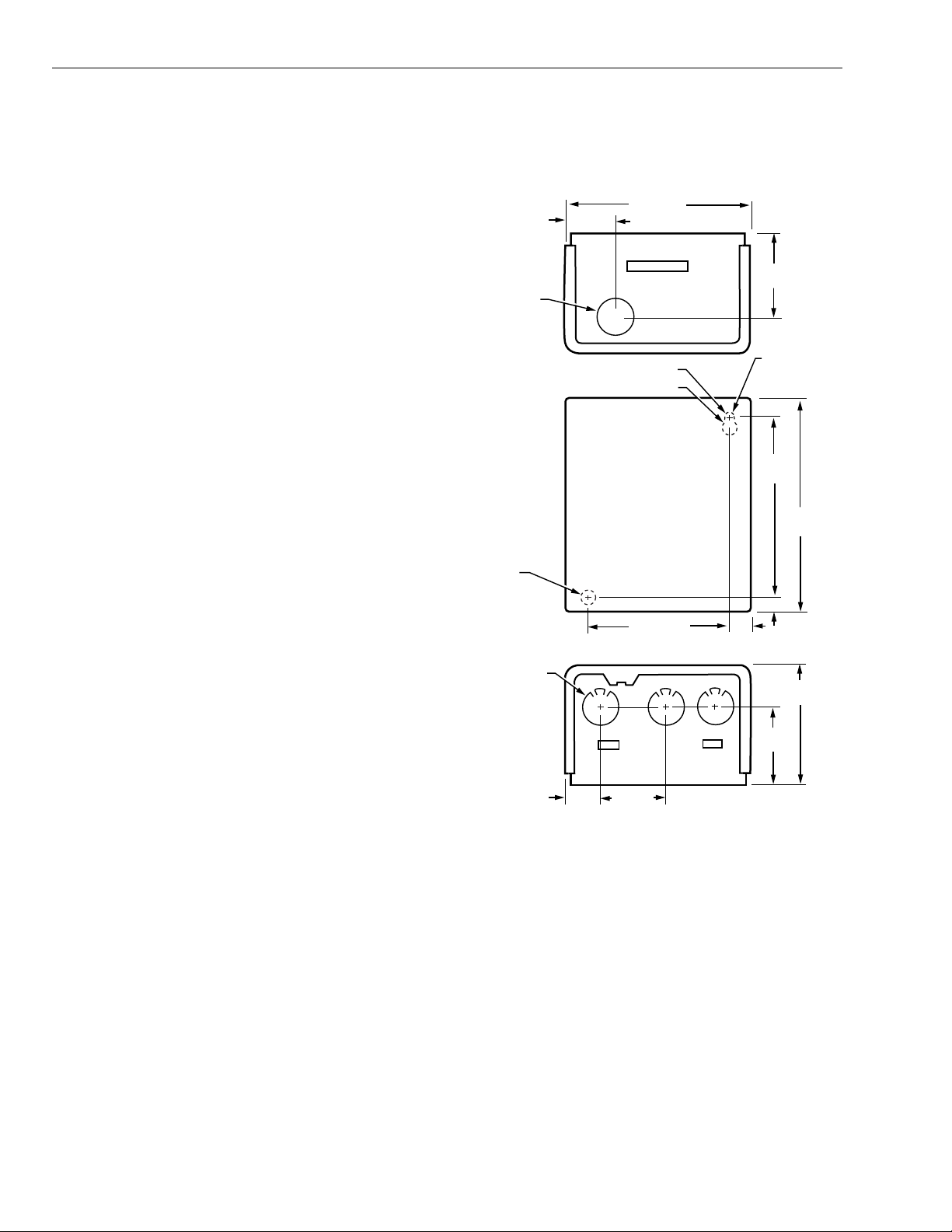
Dimensions:
7/8(22)
DIAMETER
7/32 (6)
DIAMETER
MOUNTING
HOLE
KNOCKOUT
FOR 1/2 (13)
CONDUIT (3)
Fig. 1. RA889A dimensions in in. (mm).
See Fig. 1.
1-3/8 (35)
3/16 (5) DIAMETER
3/8 (10) DIAMETER
1-1/16
(27)
4-7/16 (118)
3-11/16 (94) 5/16
1-1/4 (32)
(8)
2-1/8
(54)
KEYHOLE
TYPE
MOUNTING
HOLE
5-3/8
(137)
6-1/4
(159)
5/16 (8)
3-1/2
2-3/16
(56)
M17512
(89)
ORDERING INFORMATION
When purchasing replacement and modernization products from your TRADELINE® wholesaler or distributor, refer to the
TRADELINE® Catalog or price sheets for complete ordering number.
If you have additional questions, need further information, or would like to comment on our products or services, please write or
phone:
1.
Your local Home and Building Control Sales Office (check white pages of your phone directory).
2.
Home and Building Control Customer Logistics
Honeywell Inc., 1885 Douglas Drive North
Minneapolis, Minnesota 55422-4386 (612) 951-1000
In Canada—Honeywell Limited/Honeywell Limitée, 155 Gordon Baker Road, North York, Ontario M2H 3N7.
International Sales and Service Offices in all principal cities of the world. Manufacturing in Australia, Canada, Finland, France,
Germany, Japan, Mexico, Netherlands, Spain, Taiwan, United Kingdom, U.S.A.
68-0216—2 2
Page 3
RA889A SWITCHING RELAY
Cross Reference:
models. See Table 1 for additional cross reference
information.
Thermostat Compatibility:
and most electromechanical 2- or 3-wire. Select thermostats
with 0.12A heating anticipator setting to match the electrical
rating of the switching relay.
Manu-
facturer Model
Honeywell RA889A L1 L2 COM N.O. N.C. X1 X2 W(T) R(T) C —
Honeywell
a
RA889A has one set of COM/N.O. relay contacts. Use R8845U if two sets are required.
b
RA89A has lower output load rating. Check load requirements.
The RA889A replaces many Honeywell
All Honeywell electromechanical
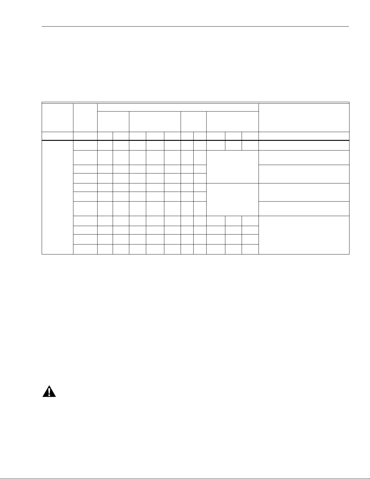
Table 1. RA889A Replacement Cross Reference.
Connections
Input Line
Voltage Power Relay
a
RA89A
R182A
R182B 1 2 8 6 7 B R Requires jumper between X1 and
R182C
R482B 1 2 8 6 7 ——Jumper R(T) to
R482C
R482J
R882A
R882B ——867——W — B
R882C
R882J
123 4 ———TT——
a
127 8 — B R See Fig. 6
b
128 6 7 BR
b
128 6 7 ——
b
126 8 7 —— Line voltage inputs go to L1 and L2.
a
——87———W — B —
b
——867——W — B
b
——687——1 — 2
Replacement Parts:
32002190-001 Replacement Relay.
Relay Fuse: 1A automotive fuse.
Low
Voltage
Relay Thermostat
thermostat
connections
W(T).
Comments
Jumper L1 to COM and between X1
and R(T) in RA889A.
R(T).
Line voltage switch ed inputs go to L1
and L2. See Fig. 7B.
See Fig. 7B.
INSTALLATION
When Installing this Product . . .
1.
Read these instructio ns c aref ull y. Failure to follow them
could damage the product or cause a hazardous condition.
2.
Check the ratings given in the instructions and on the
product to make sure the product is suitable for your
application.
3.
Installer must be a trained, experienced service technician.
4.
After installation is complete, check out product operation as provided in these instructi ons .
5.
Follow local codes for installation and application.
WARNING
Electrical Shock Hazard.
Power supply can cause severe injury or death.
Transformer core not bonded.
Disconnect power supply before wiring.
MOUNTING
In replacement applic atio ns , m oun t the ne w rela y i n th e s am e
location as the old relay. For new installations, locate the rela y
vertically on a solid wall or part ition as clos e as possible to the
device to be controlled. Select a location that is easily
accessible for installation and service.
NOTE: To reduce the possible transformer hum and relay
noise that is sometimes amplified by mounting surfaces such as sheet metal, plasterboard, and similar
materials, place rubber or felt washers between the
case and the mounting surface.
1.
Position the relay and mark the mounting holes. See
Fig. 1.
2.
Start a screw in the upper right corner for the keyhole
type mounting hole. Screw it down within about 1/8 in.
(3 mm) of the surface.
3.
Hang the relay on the screw , pos ition the case, and start
the bottom screw.
4.
Tighten both screws.
3 68-0216—2
Page 4

RA889A SWITCHING RELAY
WIRING
WARNING
Electrical Shock Hazard.
Can cause serious personal injury or death.
Use only NEC Class 1 wire for all line voltage wiring
connections. Class 1 wires must be rated for at least
167°F (75°C).
All wiring must comply with all applicable electrical codes,
ordinances, and regulat ion s. Fol low all ins truc ti ons furnis he d
with the controlled equipment.
IMPORTANT
The switching relay terminals are approved only for
use with copper wires.
When two or more line-voltage load devices are to be
controlled in parallel, the total current must not exceed the
rating for the relay load. Never connect load terminals to a
load that uses more current than the amount listed in the
electrical ratings on the relay. See Table 3 for wiring length
specifications. See the schematic and typical hookups in Fig.
2 through 7.
Table 2. Wire Lengths.
Wire Size
(AWG)
T otal W ire Length
Feet Meters Feet Meters
22 120 38.0 60 18.0
20 200 61.0 100 30.5
18 300 91.5 150 45.5
16 500 152.5 250 76.0
14 800 244.0 400 122.0
Wire Length of Run to
Thermostat
OPERATION
The RA889A consists of a transformer, an Spdt line-voltage
relay, an Spst low-voltage relay and wiring terminals. When
line-voltage is applied to the tra nsform er, the relay is powered
on thermostat contact closure. The relay may also be used to
provide electrical isolation in low-voltage circuits, if powered
from a 24 Vac or 24 Vdc external source connected to W(T)
and C. Fiber barriers separate line- and low-voltage
connections.
CHECKOUT
1.
Keep the cover on the relay during normal operation
and remove only for service and checkout.
2.
Relay contacts require no cleaning; they are arranged
to close with a wiping action and are self-cleaning. The
contacts may turn black after being in service for some
time; this discoloration does not prevent proper operation.
3.
After installation is complete , operate syste m through at
least one cycle from the controller to make certain the
relay controls the equipment as intended.
.TROUBLESHOOTING
Test Button
This connection is the same as a call for heat connection
between the R(T) and W(T) terminals.
Relay LED
This LED lights whenever there is 120 Vac (L1) on the N.O.
terminal (when COM/N.O. relay contacts are closed).
LOW VOLTAGE (CLASS 2)
2-WIRE THERMOSTAT
AUTOMOTIVE
FUSE
R(T) W(T)
RELAY
LED
G
L2 L1
1
L1
TO
HOTL2
POWER
POWER SUPPLY. PROVIDE OVERLOAD PROTECTION
1
AND DISCONNECT MEANS AS REQUIRED.
1
C
N.O.COM
LOAD 1
N.C.
TO
POWER
X2X1
LOW-VOLTAGE
POWERPILE®
M14295
Fig. 2. RA889A internal schematic and typical hookup.
68-0216—24
Page 5

RA889A
RELAY
RA889A SWITCHING RELAY
T87F T87F T87F
RA889A RA889A
W(T)R(T)
W(T)R(T)
W(T)R(T)
COM
L2L1
L1
(HOT)
1
PUMP PUMP PUMP
X2X1N.O.
COM
L2L1
X2X1N.O.
COM
L2L1
X2X1N.O.
L2
GL2L1 T T
2
C1 C2
L7148A/L8148A
B2 B1
F
3
C554
F
T
ORANGE
WHITE
BLACK
BURNER
AND
IGNITION
T
R8184G
POWER SUPPLY. PROVIDE DISCONNECT MEANS AND OVERLOAD PROTECTION AS REQUIRED.
1
2
CONTROL CASE MUST BE CONNECTED TO EARTH GROUND. USE GROUNDING SCREW PROVIDED.
3
B1 IS 1/4 IN. TAB TERMINAL.
M14301
Fig. 3. RA889A hookup for L7148A/L8148A in an oil-fired, tankless hot water, zoned, pump system.
T87F T87F T87F
R(T)
RA889A RELAY
W(T)
RA889A RA889A
R(T) W(T)R(T) W(T)
L1
(HOT)
1
L2
GL2L1 T T
2
C1 C2
L7148F/L8148E
Fig. 4. RA889A hookup for L7148F/L8148E in a gas-fired, 24V, zoned, pump system.
N.O.
L1
X1 X2
N.O.
L2
COM
COM
L2
L1
X1 X2
PUMP PUMP PUMP
B2 B1
3
TR
THTR
TH
LOW VOLTAGE
GAS VALVE
(eg, VR8300)
POWER SUPPLY. PROVIDE DISCONNECT MEANS AND
1
OVERLOAD PROTECTION AS REQUIRED.
CONTROL CASE MUST BE CONNECTED TO EARTH GROUND.
2
USE GROUNDING SCREW PROVIDED.
B1 IS 1/4 IN. TAB TERMINAL.
3
5 68-0216—2
COM
N.O.
L2
L1
X1 X2
M13314
Page 6

RA889A SWITCHING RELAY
ZONE 1
THERMOSTAT
ZONE 2
THERMOSTAT
ZONE 3
THERMOSTAT
ZONE 4
THERMOSTAT
R8888
R W
R W R W R W
R C A B C
20 VA
ZONE 1
ZONE 2
ZONE 3
ZONE 4
H1 H2
L2 L1 L1 ZC
L2 L1
C2 C1
C2 C1 C2 C1 C2 C1
G
4
L1
(HOT)
1
CIRCULATOR
PUMP 1
CIRCULATOR
PUMP 2
CIRCULATOR
PUMP 3
CIRCULATOR
PUMP 4
2
L2
3
RA889A
L2
CIRCULATOR
PUMP 5
L1
N.O.
X1
X2
COM
R(T)
W(T)
G
ZONE 5
THERMOSTAT
1
ZC
TO APPROPRIATE
CONNECTIONS
H1
AS REQUIRED
BY THE SYSTEM.
H2
H1-H2 TYPICALLY
CONNECTED TO
T-T OF BURNER
CONTROL SYSTEM.
CONTROL CASE MUST BE CONNECTED TO EARTH GROUND.
1
USE GROUNDING SCREW PROVIDED.
USE COPPER CONDUCTORS ONLY. FOR ALL CLASS 1
2
CONNECTIONS, USE WIRE RATED FOR AT LEAST 167°F (75°C).
Fig. 5. R8888 zone expansion using RA889A Switching Relays.
THREE-WIRE
LOW VOLTAGE
(SERIES 10)
THERMOSTAT
W(T)
R(T)
MAKES CONTACT ONLY ON TEMPERATURE FALL.
1
R(T)
C
W(T)
RA889A
1
B
X2
X1
TWO-WIRE
LOW VOLTAGE
(SERIES 80)
THERMOSTAT
R(T)
W(T)
C
RA889A
X2
X1
M13316
Fig. 6. RA889A thermostat connections.
POWER SUPPLY. PROVIDE DISCONNECT MEANS AND OVERLOAD
3
PROTECTION AS REQUIRED.
CONNECT L1-ZC JUMPER, IF REQUIRED.
4
M13321
68-0216—26
Page 7

A. FOR 24V THERMOSTAT CONTROL
L1, (HOT)
NEUTRAL
LINE VOLTAGE
CONTROLLED
OUTPUTS
L1
L2
COM
N.O.
N.C.
RA889A
R(T)
W(T)
C
X1
X2
B. FOR LINE VOLTAGE CONTROL
LINE VOLTAGE
CONTROL
3
NEUTRAL
L1
L2
COM
N.O.
N.C.
RA889A
R(T)
W(T)
C
X1
X2
THERMOSTAT
R
W
OPTIONAL
C
2
LOW VOLTAGE
CONTROLLED OUTPUT
JUMPER
RA889A SWITCHING RELAY
C. FOR EXTERNAL SEPARATE LOW VOLTAGE POWER SOURCE
RA889A
R(T)
W(T)
24V CONTROLLER
C
INPUT SUPPLY
X1
X2
NEUTRAL
1
L1
L2
COM
N.O.
N.C.
1 REQUIRED FOR OUTPUT LED OPERATION.
2 FOR SERIES 10 OR OTHER HARDWIRED ELECTRONIC 3-WIRE
THERMOSTATS.
3 WARNING! ELECTROCUTION HAZARD. POWER SUPPLY CAN
CAUSE SEVERE INJURY OR DEATH. DISCONNECT POWER BEFORE
WIRING OR SERVICING L1. POWERED RELAYS MUST BE WIRED AS
DRY CONTACTS.
M13317A
Fig. 7. RA889A control options.
7 68-0216—2
Page 8

Home and Building Control Home and Building Control Honeywell Asia Pacific Inc.
Printed in U.S.A. on recycled
paper containing at least 10%
post-consumer paper fibers.
Honeywell Inc. Honeywell Limited-Honeywell Limitée Room 3213-3225
Honeywell Plaza 155 Gordon Baker Roa d Sun Hung Kai Centre
P.O. Box 524 North York, Ontario No. 30 Harbour Road
Minneapolis, MN 55408-0524 M2H 3N7 Wanchai
Hong Kong
Honeywell Latin Amer ic a n Region Ho ne yw ell E ur op e S.A.
480 Sawgrass Corporate Parkway 3 Avenue du Bourget
Suite 200 1140 Brussels
Sunrise FL 33325 Belgium
68-0216—2 G.R. Rev. 5-00 www.honeywell.com
 Loading...