

Honeywell RA889 Installation Manual
APPLICATION
The RA889A Switching Relay provides intermediate
switching of line- and low-voltage devices from a line- or
low-voltage controller and is typically applied in hydronic
heating systems.
SPECIFICATIONS
Electrical Ratings:
Voltage: 120 Vac, 60 Hz.
Thermostat Heat Anticipator Setting: 0.12A.
Transformer Ratings:
Primary: 120 Vac, 60 Hz.
Secondary: 24 Vac, 12 VA maximum; 9 VA available for
external loads. Secondary is protected by replaceable
1A automotive fuse.
Contact Ratings:
15 AFL, 30 ALR; maximum connected load 2000 VA.
Switching Action:
Spdt, plus extra low voltage Spst.
Electrical Connections:
No. 8 captivated wire clamp screw terminals.
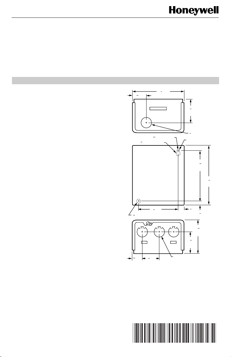
Dimensions:
See Fig. 1.
Cross Reference:
The RA889A replaces many Honeywell models. See
Table 1 for additional cross reference information.
Replacement Parts:
Replacement Fuse: Use a 1A automotive fuse.
RA889A
Switching Relay
INSTALLATION INSTRUCTIONS
1
4 (108)
3
(2) DIAMETER
32
(13) DIAMETER
1
3 (89)
2
3
1 (35)
8
4
7
1
8
(48)
7
(22) DIAMETER
8
KEYHOLE TYPE
MOUNTING HOLE
3
(10)
8
2
(75)
7
1
8
(48)
KNOCKOUT FOR
1/2 (13) CONDUIT (3)
4
(114)
15
16
1
2
3
8
(10)
M3823A
5
(133)
1
4
5
1 (29)
32
1
2
7
(6) DIAMETER MOUNTING HOLE
32
25
(20)
32
Fig. 1. RA889A dimensions in in. (mm).
®U.S. Registered Trademark
Copyright © 1999 Honeywell Inc. • All Rights Reserved
X-XX UL
69-1293-1
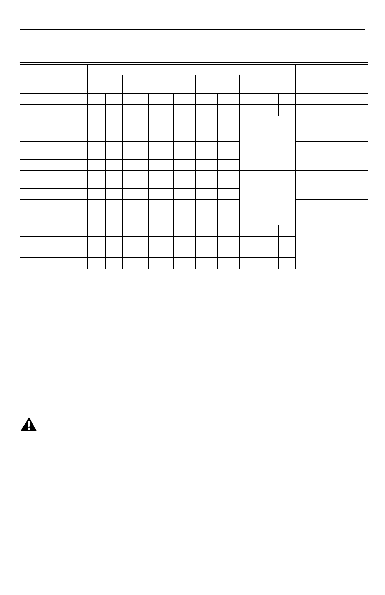
RA889A SWITCHING RELAY
Table 1. RA889A Replacement Cross Reference.
Connections
Manu-
facturer Model
Honeywell RA889A L1 L2 COM N.O. N.C. X1 X2 W(T) R(T) C —
Honeywell RA89Ab12 3 4 ——— TT——
Honeywell R182Ab12 78—BRSee Fig. 8
Honeywell R182B 1 2 8 6 7 B R Requires jumper
Honeywell R182Ca12 8 6 7 B R
Honeywell R482B 1 2 8 6 7 — — Jumper R(T)
Honeywell R482Ca12 8 6 7 — —
Honeywell R482Ja12 687—— Line voltage inputs
Honeywell R882Ab—— 8 7 ———W—B
Honeywell R882B — — 8 6 7 — — W — B
Honeywell R882Ca—— 8 6 7 — — W — B
Honeywell R882Ja—— 6 8 7 — — 1 — 2
a
RA889A has one set of COM/N.O. relay contacts. Use R8845U if two sets are required.
b
RA889A has lower output load rating. Check load requirements.
Input Line
Voltage Power Relay
Low Voltage
Relay Thermostat Comments
thermostat
connections.
to W(T).
Jumper L1 to COM and
between X1 and R(T) in
RA889A.
between X1 and R(T)
Line voltage switched
inputs go to L1 and L2.
See Fig. 7B.
go to L1 and L2. See
Fig. 7B.
—
INSTALLATION
When Installing this Product . . .
1. Read these instructions carefully. Failure to follow
them could damage the product or cause a hazardous condition.
2. Check the ratings given in the instructions and on
the product to make sure the product is suitable for
your application.
3. Installer must be a trained, experienced service
technician.
4. After installation is complete, check out product
operation as provided in these instructions.
5. Follow local codes for installation and application.
WARNING
Electrocution Hazard.
Power supply can cause severe injury,
or death.
Transformer core not bonded.
Disconnect power supply before wiring.
69-1293—1
MOUNTING
In replacement applications, mount the new relay in the
same location as the old relay. For new installations,
locate the relay vertically on a solid wall or partition as
close as possible to the device to be controlled. Select a
location that is easily accessible for installation and
service.
NOTE: To reduce the possible transformer hum and
relay noise that is sometimes amplified by
mounting surfaces such as sheetmetal,
plasterboard, and similar materials, place
rubber or felt washers between the case and
the mounting surface.
1. Position the relay and mark the mounting holes. See
Fig. 1.
2. Start a screw in the upper right corner for the
keyhole type mounting hole. Screw it down within
about 1/8 in. (3 mm) of the surface.
3. Hang the relay on the screw, position the case, and
start the bottom screw.
4. Tighten both screws.
2
 Loading...