

Page 1
Honeywell
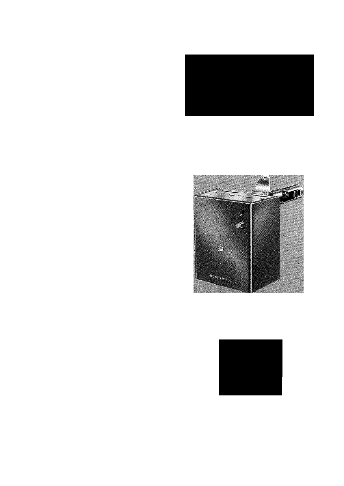
THESEONE-PIECE.STACK-MOUNTEDOIL BURNER
PRIMARY CONTROLS CYCLE THE BURNER ON
THERMOSTAT DEMAND AND SHUT DOWN THE
BURNER ON FLAME LOSS OR SYSTEM MALFUNC
TION.
□ Combine a Protectorelay unit for cyciing the burner
and a Pyrostat flame detector for sensing temperature
changes of fiue gases up to 1000° F [556° C].
□ RA116A is used with intermittent ignition burners
(formerly called constant ignition burners).
□ RA117A and RA817A are used with interrupted
ignition burners (formeriy cailed intermittent ignition
burners).
PROTECTORELAY
OIL BURNER
CONTROLS
□ Used with line voltage or 24V controllers.
□ Safety switch may be manually tripped on all models.
□ On RA116A, lockout occurs if fiame is not re-es-
tabiished during safety switch timing.
□ On RA117A and RA817A, flame or power failure is
followed by a one minute (approximate) scavenging
period and one attempt to re-establish flame. Lockout
occurs if flame is not re-established.
□ Manual resetof safety switch is required after ignition
failure completely shuts off main burner.
RA116A
RA117A
RA817A
D.T.
3-91
Form Number 68-0119
©Honeywell Inc. 1991
Page 2
IMPORTANT
THE SPECIFICATIONS GIVEN IN THIS PUBLICATION DO NOT INCLUDE NORMAL MANUFACTURING
TOLERANCES. THEREFORE, UNITS MAY NOT MATCH THE LISTED SPECIFICATIONS EXACTLY. ALSO,
PRODUCTS ARE TESTED AND CALIBRATED UNDER CLOSELY CONTROLLED CONDITIONS, AND SOME
MINOR DIFFERENCES IN PERFORMANCE CAN BE EXPECTED IF THOSE CONDITIONS ARE CHANGED.
SUPER TRADEUNE MODELS
SUPER TRADELINE controls offer features not
available on TRADELINE or standard models, and
are designed to replace a wide range of Honeywell
and competitive controls.
SUPER TRADELINE MODELS AVAILABLE:
RA117A Stack Mounted Protectorelay
Special SUPER TRADELINE packaging with
cross reference label and SUPER TRADELINE in
struction sheet.
TRADELINE MODELS
TRADELINE controls offer features not available
on standard models and are designed to replace a wide
range of Honeywell and competitive controls.
TRADELINE MODELS:
RA116A Stack Mounted Protectorelay
Special TRADELINE packaging with cross refer
ence label and TRADELINE instruction sheet.
STANDARD MODELS
MODEL
NUMBER TYPE OF IGNITION
RA116A
RA117A Interrupted ignition^
RA817A Interrupted ignition'^
» Lockout occurs if flame is not re-established during the safety switch timing.
^ Flame or power failure is followed by a one minute (approximate) scavenging period and one attempt to re-establish the
flame. Lockout occurs if flame is not re-established.
Intermittent ignition^
(formerly called
constant ignition)
(formerly called
intermittent ignition)
(formerly called
intermittent ignition)
24V
THERMOSTAT
2- wire
3- wire
series 10
2- wire
3- wire
series 10
2-wire 550 VA
IGNITION
RATING
360 VA 120V/60HZ
550 VA
INPUT
VOLTAGE
120V/60 Hz
110V/50 Hz
120V/60 Hz
220V/50 Hz
240V/60 Hz
FOR ORDERING INFORMATION WHEN PURCHASING REPLACEMENT AND MODERNIZATION PRODUCTS FROM YOUR
TRADEUNE WHOLESALER OR YOUR DISTRIBUTOR, REFER TO THE TRADEUNE CATALOG OR PRICE SHEETS FOR
COMPLETE ORDERING NUMBER, OR SPECIFY:
1. Order number. TRADEUNE or SUPER TRADEUNE.
2. Input voltage and frequency.
IF YOU HAVE ADDITIONAL QUESTIONS, NEED FURTHER INFORMATION, OR WANT TO COMMENT ON OUR PRODUCTS
OR SERVICES, PLEASE WRITE OR PHONE:
1. YOUR LOCAL HONEYWELL RESIDENTIAL AND BUILDING CONTROLS DIVISION SALES OFFICE (CHECK
WHITE PAGES OF PHONE DIRECTORY).
2. RESIDENTIAL AND BUILDING CONTROLS CUSTOMER SATISFACTION
HONEYWELL INC., 1885 DOUGLAS DRIVE NORTH
MINNEAPOLIS, MINNESOTA 55422-4386
(612) 542-7500
IN CANADA: HONEYWELL CONTROLS LIMITED
740 ELLESMERE ROAD
SCARBOROUGH, ONTARIO M1P 2V9
INTERNATIONAL SALES AND SERVICE OFFICES IN ALL PRINCIPAL CITIES OF THE WORLD.
Page 3

AMBIENT TEMPERATURE:
Operating: 0° F to 104” F [-18“ C to 40° C].
Shipping: -40° F to 150° F [-40° C to 66° C],
DIMENSIONS: Referto Fig. 1.
ELECTRICAL RATINGS (amperes):
Motor Ratings
110V/50 Hz
120V/60 Hz
Full Load
Locked Rotor
ELEMENT INSERTION LENGTH:
Adjustable from 3-1 /2 to 5-1 /2 inches [89 to 140 millime
ters].
7.4 3.7
44.4
220V/50 Hz
240V/60 Hz
22.2
COMPETITIVE CROSS-REFERENCE
The RA116A replaces the following competitive devices:
MOUNTING FLANGE:
Available for 6 inch [152 millimeter] diameter pipe (refer
to Fig. 2). Can also be flattened for flat-mounting applica
tions.
24V THERMOSTAT HEAT ANTICIPATOR CURRENT:
0.4A.
LINE VOLTAGE THERMOSTAT OR CONTROLLER
(RA116A, RA117A):2wire, 8A. Requires jumper across
W and B terminals. Refer to Fig. 5 or 7.
SAFETY SWITCH TIMING: 75 Seconds (nominal).
APPROVALS:
UNDERWRITERS LABORATORIES INCORPORATED
LISTED (RA116A, RA117A ONLY): File Number
MP268, Guide Number MCCZ.
HONEYWELL WHITE RODGERS GENERAL ELECTRIC
R116A,B
R124A,B 611-1
R134A 611-31
R168A 611-33
R494A 615
RA116A,B 6L18
RA416A
RA816A,Db
PENN ITT GENERAL
664
670
680 R96G102DC
3 A Detroit 3-wire thermostat must be replaced by a 2-wire thermostat with a suitable heat anticipator.
^ When replacing a model having an F or O terminal to power a clogged filter indicator light, provide a separate transformer
for the light.
The RA117A replaces the following competitive devices:
HONEYWELL WHITE RODGERS
R116A,B
R117A 603 A101B2
R123A,B 610-2 CR7856
R124A,B 610-32
R134A 611-1
R168A 611-31
R494A
RA116A,B
RA117A
RA416A
RA816A
RA817A,C
RA817A,C°-C
603
5200 JM
R96A102A
602
615
6L18
A101B2
CR7865
MERCOID
GENERAL ELECTRIC
A101A2
GENERAL PERFEX
5200
5300
DETROIT
CA7013
CA702°
GENERAL PERFEX
5200
5230
5520
5525^
DELCO PENN ITT GENERAL
COA 664 5200
COA-1
® A Detroit 3-wire thermostat must be replaced by a 2-wire thermostat with a suitable heat anticipator.
When replacing a model having an F or O terminal to power a clogged filter indicator light, provide a separate transformer
for the light.
^ Do not use RA117A to replace this control where timed ignition is required for a wall-flame burner.
670 R96A102A
672 R96G102DC
680
682
MERCOID DETROIT
JM
JM1
CA70ia
CA702^
68-0119
■■ ■' 1', , . I' 'i "
]■
Page 4

WHEN INSTALLING THIS PRODUCT...
1. Read these instructions carefully. Failure to follow
them could damage the product or cause hazardous
condition.
2. Check the ratings given in these instructions and on
the product to ensure the product is suitable for your
application.
3. Ensure the installer is a trained, experienced service
technician.
4. After completing installation, use these instructions
to check product operation.
CAUTION
1.
Do not bend contact arms or stops on the Py rostat
detector mechanism or make any adjustments
other than those given in the instructions.
Remove the cardboard packing behind the drive
2.
shaft lever by pushing the packing up and pulling
it straight, out over the top of the lever. Do not
remove packing by pulling sideways.
3. Ensure all wiring complies with applicable codes
and ordinances.
MOUNTING (Refer to Fig. 2)
Followthe mounting instructionssuppliedbythe furnace,
boiler, or burner manufacturer, if available. Otherwise, use
the instructions provided below.
When replacing one of the controls listed on page 3,
identify each leadwire as it is removed from the old control
by marking the wire with the number of the RA116A or
RA117A terminal to which it will be connected. Refer to
Table 1 and 2 to translate the old terminal identifications to
the new RA116A or RA117A terminal identifications.
TABLE 1—IDENTIFYING TERMINALS FOR RA116A
TERMINAL TERMINAL
IDENTIFICATION
ON OLD CONTROL
1, LH,or HOTLINE
2, LG, or LINE
3, 4, M, or MOTOR
TABLE 2—IDENTIFYING TERMINALS FOR RA117A
TERMINAL
IDENTIFICATION
ON OLD CONTROL
1, LH, or HOTLINE
2, LG, or LINE
3, M, or MOTOR
4, 1, or IGNITION
If the position of the old control was satisfactory, install
the new RA116Aor RA117A in the same location as the old
one, making sure to insert the bimetal element the same
distance into the stack as the old element. If the old
element was inserted more than 5-1 /2 inches [140 millime
ters], insert the new control 5-1/2 inches [140 millimeters]
into the stack.
If the position of the old control was not satisfactory,
close the old holes tightly with a metal plate and follow
these instructions.
1. Follow these location considerations.
REPLACEMENT.
IDENTIFICATION ON
NEW RA116A
1
2
3
REPLACEMENT.
TERMINAL
IDENTIFICATION ON
NEW RA117A
1
2
3
4
■ ■■■■•. '
I
Page 5

A DO NOT FORCE THE COLLAR OF THE MOUNTING FLANGE PAST THE STOP.
FIG. 2—MOUNTING AND LOCATION CONSIDERATIONS.
• Locate the control between the boiler or furnace and
draft regulator.
• Locate the control as near as possible to the boiler
or furnace.
• If mounting in an elbow, locate the element near the
outer curve where the hottest gases flow.
• Do not locate the element where the temperature
may exceed 1000° C [556° С].
2. Cut a 1 -3/8 inch [35 millimeter] hole in the stack at the
location desired.
3. Drill two holes and fasten the mountihg flange using
the screws provided. The flange should fit the mounting
surface snugly, but it may be bent to fit a different radius
stack or flattened to fit aflat surface. Do not force the collar
or mounting flange past the stop.
4. Insert the bimetal element at the center of the stack
in direct path of the hottest flue gasses.
5. Tighten the lockscrew.
WIRING
Follow the appliance manufacturer’s instructions, if
available. Otherwise, follow the wiring diagrams shown in
Fig. 3 through 7.
FIG. 3—RA116A WIRING DIAGRAM WITH A 24V, 3-
WIRE THERMOSTAT.
68-0119
Page 6

^{HOT)
OIL VALVE I
BURNER
RA117A
MOTOR
IGNITION
HIGH
LIMIT
<3) © (3)
2K3 i
;1K3
2X2
1K1
№
__
(COLD) ^
.SAFETY
■ SWITCH
■HEATER
PYROSTAT
J CONTACTS
SERIES 10
THERMO
STAT ^
SAFETY,
SWITCH I
A POWER SUPPLY. PROVIDE DISCONNECT MEANS AND OVERLOAD
PROTECTION AS REQUIRED.
A USE GREEN TERMINAL TO CONNECT CONTROL CASE TO GROUND.
A IF USING A TWO-WIRE THERMOSTAT, TAPE LOOSE ENDS OF RED
WIRE (IF NECESSARY).
A CONTACTS BREAK IN SEQUENCE ON TERMPERATURE RISE.
A TO REPLACE AN INTERMITTENT IGNITION DEVICE (FORMERLY
CALLED CONSTANT IGNITION), CONNECT IGNITION LEADWIRE TO
TERMINAL 3, INSTEAD OF TERMINAL4.
Mt)
©7?T] 1K
^(T)
Hh
1K2
■wi
-V
Ar
2K1 i (HOT)
4JÍ4-
2K
1
________
LI
FIG. 4—RA116A WIRING DIAGRAM WITH A LINE
VOLTAGE THERMOSTATOR CONTROLLER.
FIG. 5—RA117A WIRING DIAGRAM WITH A 24V, 3-
WIRE THERMOSTAT.
A POWER SUPPLY. PROVIDE DISCONNECT MEANS AND OVERLOAD
PROTECTION AS REQUIRED.
A USE GREEN TERMINAL TO CONNECT CONTROL CASE TO GROUND.
A CONTACTS BREAK IN SEQUENCE ON TERMPERATURE RISE.
FIG. 6—RA117A WIRING DIAGRAM WITH A LINE VOLTAGE THERMOSTAT OR CONTROLLER.
: f: ;
I',
y
Page 7

A POWER SUPPLY. PROVIDE DISCONNECT MEANS AND OVERLOAD
PROTECTION AS REQUIRED.
A USE GREEN TERMINAL TO CONNECT CASE TO GROUND.
A CONTACTS BREAK IN SEQUENCE ON TERMPERATURE RISE.
FIG. 7—RA817A WIRING DIAGRAM.
OPERATION
The schematic diagrams show all systems in the idle
condition:
• Burner off, no call for heat.
• Pyrostat contacts closed (RA116A).
• "Cold”contactsclosed, “hof’contacts open (RA117A,
RA817A).
• Safety switches closed.
• All relays de-energized.
NORMAL OPERATING SEQUENCE
On a thermostat (or line voltage controller) call for heat,
the ignition, oil valve, and burner motor start. The safety
switch begins heating. Afterthe burner flame is established,
the stack temperature rises and expands the bimetal
detector element. The Pyrostat contacts open (RA116A) or
the "hot” contacts close and the “cold” contacts open
(RA117A, RA817A), de- energizing the safety switch heater.
The ignition circuit de-energizes (RA117A, RA817A only).
When the call for heat is satisfied, the system returns to
the idle condition.
IGNITION FAILURE
Iftheburnerflameis not established within approximately
75 seconds (nominal) of a thermostat (or line voltage
controller) call for heat, the Pyrostat contacts (RA116A) or
“cold” contacts (RA117A, RA817A) remain closed. During
that time, the safety switch is heated. If the burner flame is
not established after 75 seconds (nominal), the system
locks out and cannot be started again until the safety switch
is manually reset.
BURNER FLAME FAILURE DURING THE RUNNING
CYCLE
RA116A
The loss of burner flame reducesthe stacktemperature,
closes the Pyrostat contacts, and energizes the safety
switch. If the burner flame is not re-established within the
75 second (nominal) safety switch timing, the system locks
out and cannot be started again until the safety switch is
manually reset.
RA117A, RA817A
The loss of burner flame reducesthe stacktemperature,
opens the "hot” contacts, and shuts the system down by
de-energizing the 2K burner motor relay. After a one
minute (approximate) scavenging period, the "cold” con
tacts close and energize the safety switch heater. If the
thermostat (or line voltage controller) is still calling for heat,
the Protectorelay control makes one attempt to restart the
system. If the burner flame is not re-established in 75
seconds (nominal), the system locks out and cannot be
started again until the safety switch is manually reset.
POWER FAILURE DURING THE RUNNING CYCLE
A power failure shuts off the ignition and burner motor.
If the thermostat is still calling for heat when power is
restored, the stack temperature must cool and return the
system to the idle position. Once the system returns to the
idle condition, it begins the normal operating sequence.
'■ fVv'':'
Ikv '
''i'' 'i'
V
-i'-'
■1'.
68-0119
.i'L';:
Page 8

STARTUP AND CHECKOUT
WARNING
FIRE HAZARD
CAN CAUSE SEVERE BURNS
START THE SYSTEM
1. Ensure the Pyrostat detectors are in step.
2. Push in and release the safety switch reset button.
3. Open the hand valve in the oil supply line.
4. Set the limit control and thermostat to call for heat.
5. Close the line switch. The burner should start.
Ensure the combustion chamber is free of oil or
oil vapor before starting system.
STEP THE PYROSTAT DETECTOR CONTACTS
The detector contacts are actuated by a friction clutch
that is mounted on a rod connected directly to the heatactuated element. Occasionally, this clutch gets "out of
step” after a long period of idleness. To place the clutch and
the contacts “in step,”
1. Remove the cover.
2. Pull the lever forward 1/4 inch (Fig. 8).
3. Slowly release the lever.
4. Replace the cover.
CHECK THE SAFETY FEATURES
Simulate Flame Failure:
1. Follow the starting procedure to turn on the burner.
2. Close the hand valve in the oil supply line.
3. The RA116A locks out after 75 second (nominal)
safety switch timing. The RA117A and RA817A lock out
after one minute (approximate) scavenging period and 75
second (nominal) safety switch timing.
4. Reset the safety switch and open the hand valve in
the oil supply line.
Simulate Ignition Failure:
1. Follow the starting procedure to turn on the burner,
except do not open the oil supply hand valve.
2. Safety switch locks out after 75 second (nominal)
safety switch timing. Ignition and burner motor stops and
oil valve closes.
3. Reset the safety switch and open the hand valve in
the oil supply line.
Simulate Power Failure:
1. Follow the starting procedure to turn on the burner.
2. With the burner running, trip the circuit breaker or
remove the fuse to turn off power to the system. The burner
should stop.
3. Restore power. The burner should restart.
FIG. 8—STEPPING THE PYROSTAT DETECTOR CON
TACTS.
Check the Scavenger Timing:
1. Follow the starting procedure to turn on the burner.
2. With the burner operating normally, open and im
mediately close the line switch. The burner should stop
immediately.
3. After recycle timing (one minute approximately), the
burner should restart automatically.
If the system does not operate as described, proceed to
Troubleshooting.
Page 9

TROUBLESHOOTING AND MAINTENANCE
To cxsmpletely troubleshoot an oil burner installation,
check the burner, ignition transformer, and oil primary
control for proper operation and condition.
TRIP SAFETY SWITCH BEFORE OPERATING BURNER
MAINTENANCE
CAUTION
Tripping the safety switch shuts down the burner but
does not disconnect the power supply. Turn off the
power at the system switch or the circuit breaker
before servicing the control system, burner motor, oil
valve, or ignition to avoid electrical shock.
To trifithe safety switch, move the safety switch lever
down until the red reset button pops out. Refer to Fig. 9.
The burner wiil not operate until the safety switch is reset
by pushing the red reset button.
PRELIMINARY STEPS
Before checking the oil primary and cad cell, check out
the following parts of the burner and ignition systems.
Repair or replace controls as indicated.
1. Wiring connections, power supply, and burner motor
fuse. Ensure power is on to the controls, burner motor, and
ignition transformer.
2. Limit switch.
3. Ignition transformer.
4. Electrode gap and position.
5. Contacts between ignition transformer and electrode.
6. Oil pump pressure.
7. Oil tubing to tank.
8. Oil nozzle.
9. Oil supply.
10. Oil filter.
If the system is still not operating properly, check the oil
primary control as instructed below.
FIG. 9—TRIPPING AND RESETTING THE SAFETY
SWITCH.
CHECK THE OIL PRIMARY CONTROL
CAUTION
Since troubleshooting is done with the system pow
ered, observe all necessary precautions to prevent
electrical shock or equipment damage.
Equipment Required:
1. Screwdriver
2.0 to 300 Vac Voltmeter
3. Insulated Jumper Wires
4. Hard Surface Card (such as a business card) for
cleaning contacts
68-0119
Page 10

Burner Does Not Start When Thermostat Calls For Heat
PRELIMINARY CHECKS
1. Ensure all limit switches are closed.
2. Ensure safety switch is reset.
3. Check for the proper line voltage at the oil primary.
Proceed as follows after completing the preliminary checks.
PROCEDURE
1. Jumper the thermostat
terminals:
• Low voltage thermostat
at oil primary
• Line voltage thermostat
at thermostat
BURNER STARTS
Trouble in the thermostat circuit.
Check the thermostat and
wiring connections.
CORRECTIVE ACTION
BURNER DOES NOT START
Trouble is in the bimetal detector or
the oil primary. Put contacts in step
by pulling drive shaft lever out 1/4
inch and releasing. Refer to Fig. 8.
2. Jumper thermostat terminals
to start burner.
3. Jumper thermostat terminals
to start burner.
4. Jumper the thermostat
terminals and jumper the
normally closed contacts.
5. Jumper the thermostat
terminals and jumper the
R and B terminals on the
oil primary.
Burner Starts, Flame Is Established. Then Safety Switch Locks Out on Safety.
PRELIMINARY STEPS;
1. Reset the safety switch.
2. Clean bimetal detector contacts.
Proceed as follows after completing the preliminary checks.
Bimetal detector and oil primary
are OK.
Bimetal detector and oil primary
are OK.
Reclean the bimetal detector
contacts again and recheck
by jumpering the thermostat
terminals. If the burner starts,
bimetal detector and oil primary
are OK.
Check for broken wires, loose
connections between the bimetal
detector and the control.
Repair and recheck by jumpering
the thermostat terminals. Replace
the bimetal detector if necessary.
Clean the bimetal detector contacts
and timer contacts (if provided).
Go to step 3.
Go to step 4.
Go to step 5.
Replace the oil primary and perform
Startup and Checkout procedures.
PROCEDURE
1. Jumper thermostat
terminals to start burner.
• Low voltage thermostat
at oil primary
• Line voltage thermostat
at thermostat
2. Reset the safety switch
and jumper the thermostat
terminals to start the burner.
Honeywell Inc.
U.S.A.: 1885 Douglas Drive N.
Golden Valley, MN 55422-4386
CANADA: 740 Ellesmere Road
Scarborough, Ontario M1P 2V9
CORRECTIVE ACTION
BURNER KEEPS RUNNING
Bimetal detector and oil primary
are OK.
Bimetal detector and oil primary
are OK.
BURNER LOCKS OUT
• Clean the drive shaft, remove
the detector and clean bimetal
element. Replace the detector.
• Check the detector location. If
the stack temperature is below
300° F [149° C], replace the bimetal
detector.
Replace the oil primary and perform
Startup and Checkout procedures.
International Sales Offices in all principal cities of the world. Manufacturing in
Australia, Canada, Finland, France, Germany, Japan, Mexico, Netherlands,
Spain, Taiwan, United Kingdom, U.S.A.
PRINTED IN U.S.A.
QUALITY IS KEY
 Loading...