

Page 1
HONEYWELL I
TRADELINE
I CONTROLS
application
The R841E Electric Heating Relay is a two-switch
device used with either one 24-volt, two-wire thermo
stat to control one or two loads simultaneously; or
with two thermostats to control two independent loads.
It is a direct following relay which operates with each
cycle of the thermostat (4 to 6 cycles per hour with a
T822Dor T87F Thermostat), It has an integral trans
former. The R841E should not be used as a discon
nect switch.
INSTALLATION-
The R841E must be mounted where the ambient tem
perature is within the range of -20 to ISO F the year
around. The small size and silent operation of the
R841 allow installation in a living area, utility room
or basement. The bimetal-operated switches permit
mounting the relay in any convenient position.
2. Run line-voltage wire from heaters to relay
junction box. Using solderless connectors, make the
connections shown in Figs, 3, 4, or 5.
3. Run thermostat cable from the thermostat to the
relay. Connect to relay according to Figs, 3, 4 or 5.
ALL WIRING MUST AGREE WITH LOCAL CODES.
Be sure the power supply voltage agrees with the rat
ing on the relay label.
OPERATION
The cycling pattern of the R841E is determined by
the thermostat. On a call for heat, the thermostat
activates one or both of the low voltage resistance
heaters in the R841E. The heater drives a bimetal
that actuates the spst MICRO SWITCH* snap acting
switch. The bimetal is ambient-temperature compen
sated between -20 and 150 F. At rated voltage and
frequency, the R841E switch contacts''make''approx
imately 80 seconds (from cold start) after the thermo
stat calls for heat and break about 100 seconds after
the thermostat stops calling for heat.
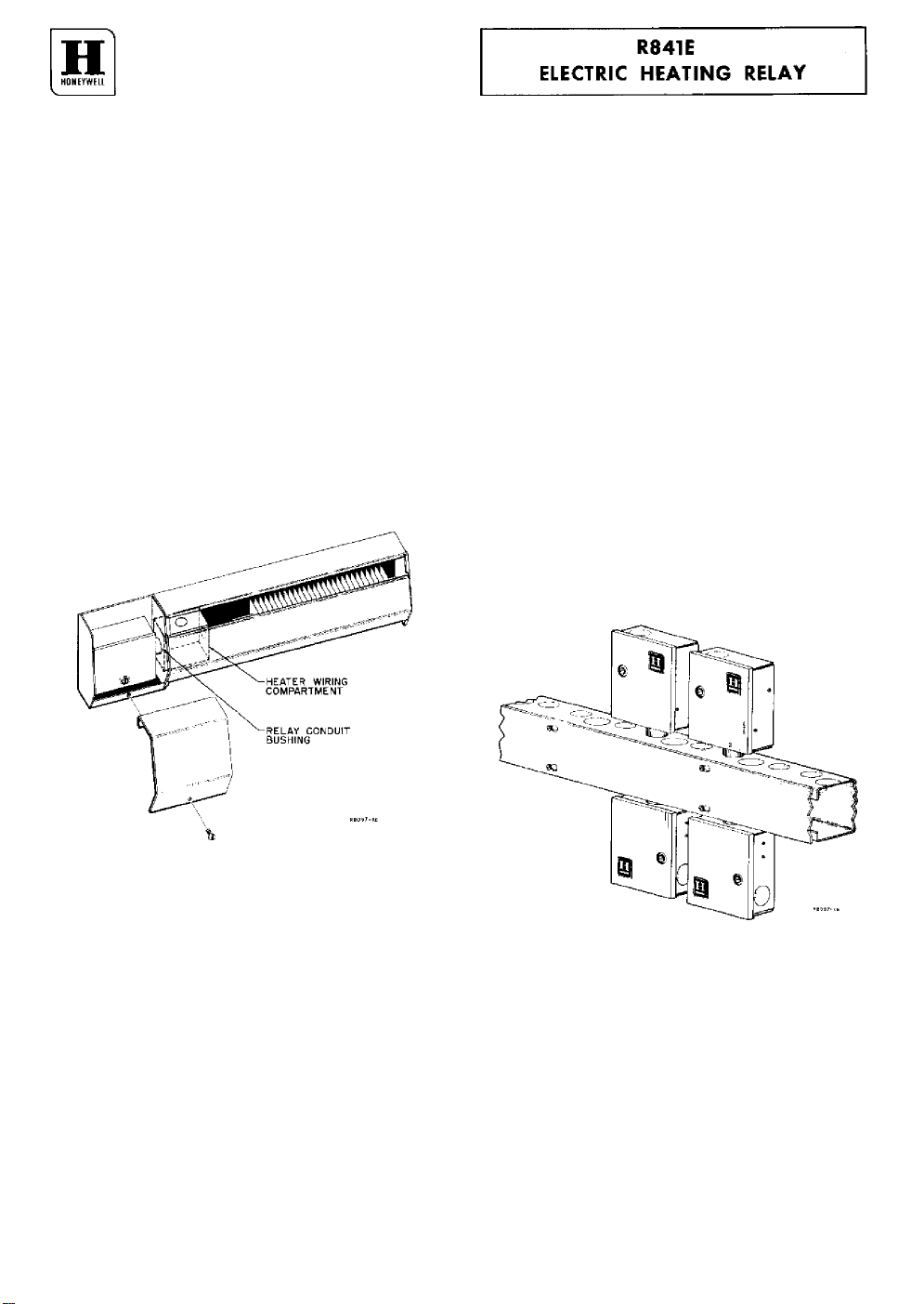
Fig. 1—Typical installation of relay in baseboard
heater.
Fig. 1 shows a typical installation within a com
partment enclosure on the end of a baseboard heater.
In this application the conduit bushing can be connect
ed to the wiring compartment in the heater. The back
of the compartment enclosure should be equipped with
embossings to clear mounting screws.
The R841E may also be mounted without compart
ment enclosure on a wireway or junction box (Fig. 2).
CAUTION: DISCONNECT POWER SUPPLY.
1. Fasten relay securely to mounting surface using
the two mounting holes in the taackplate, or the con
duit bushing.
♦Trademark
5-68
J. C.
Fig. 2—Four relays mounted on wireway.
CHECKOUT-
After mounting and wiring have been completed,
turn on the power supply. Set the thermostat above
room temperature until the electric heating equipment
starts (allow about 80 seconds from cold start). Per
mit the system to operate long enough to prove the
heating equipment functions properly. Return the
thermostat to the desired room temperature before
leaving the installation.
Fofrn Numbiir 93—6804
Rasidential Div.
Page 2
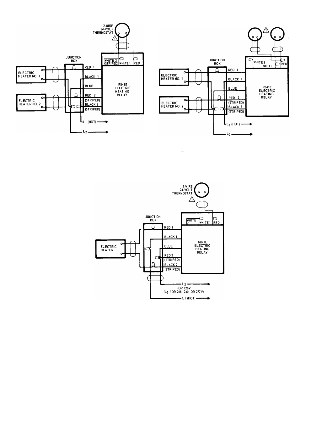
2-WIRE 2-WIRE
24-VOLT 24-VOLT
THERMOSTAT THERMOSTAT
NO. 2 NO. 1
FOR 120 V
(L3 FOR 208, 240 OR 277V)
/l\ SET ADJUSTABLE HEAT ANTICIPATION HEATERS AT 0.4 AMP.
Fig. 3—Typical wiring hookup for one thermostat op
erating two loads simultaneously.
^SET ADJUSTABLE HEAT ANTICIPATION HEATER AT 0.4 AMP.
FOR 120 V
(L3 FOR 208, 240 OR 277V)
A\ SET ADJUSTABLE HEAT ANTICIPATION HEATERS AT 0.2 AMP.
Fig. 4—Typical wiring hookup for two thermostats,
each with its own load.
Fig. 5—Typical wiring hookup for one thermostat
connected to one load so that both sides of
the single phase line are switched.
V HONEYWELL • • Minneapolis, Minnesota 55408
Scarborough, Ontario
 Loading...