

Page 1
Honewvell
-u
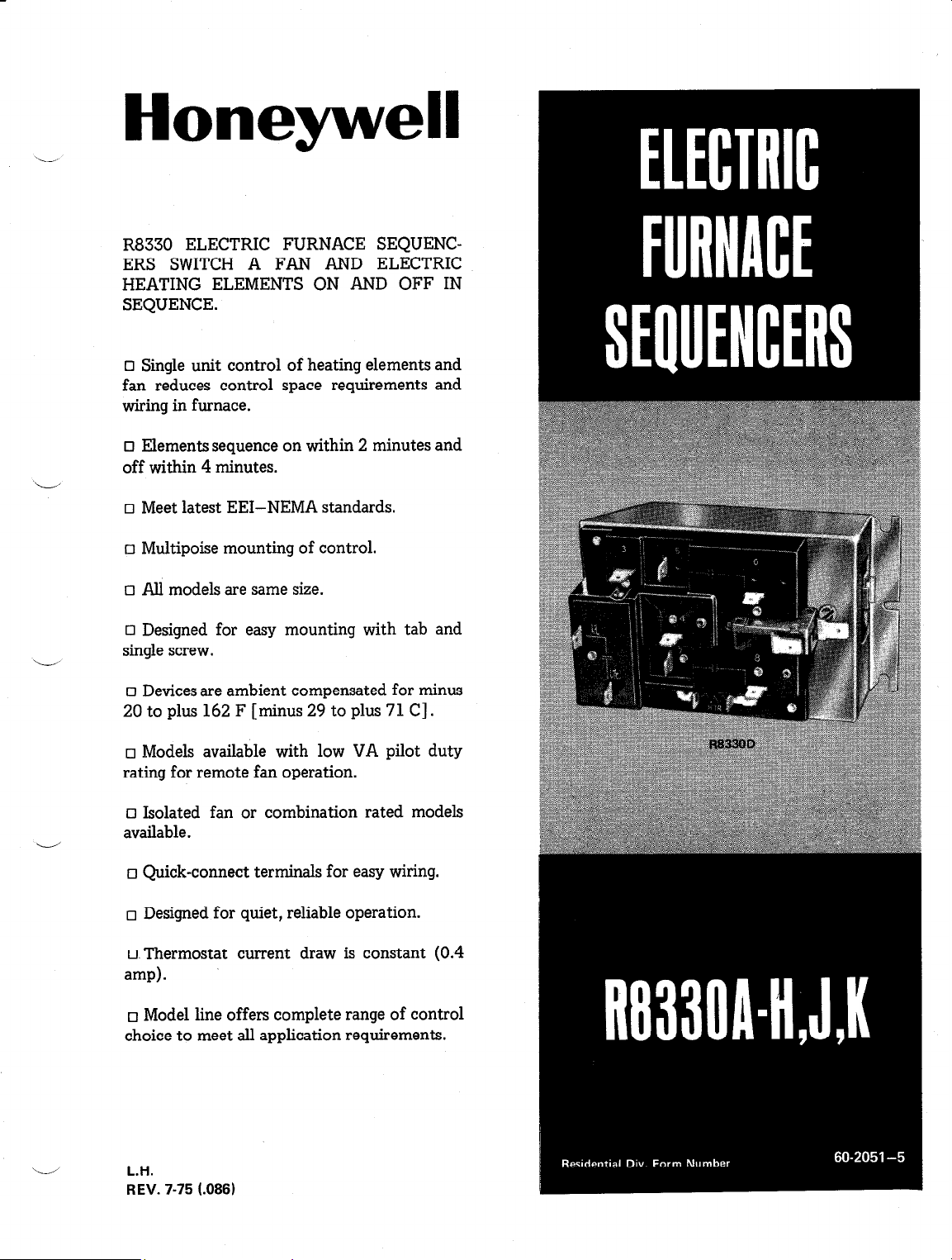
R8330 ELECTRIC FURNACE SEQUENCERS SWITCH A FAN AND ELECTRIC
HEATING ELEMENTS ON AND OFF IN
SEQUENCE.
q Single unit control of heating elements and
fan reduces control space .requirements and
wiring in furnace.
q Elements sequence on within 2 minutes and
off within 4 minutes.
q Meet latest EEI-NEMA standards.
o Multipoise mounting of control.
q All models are same size.
q Designed for easy mounting with tab and
single screw.
q Devices are ambient compensated for minus
20 to plus 162 F [ minus29toplus71C].
q Models available with low VA pilot duty
rating for remote fan operation.
EI Isolated fan or combination rated models
available.
q Quick-connect terminals for easy wiring.
q Designed for quiet, reliable operation.
q .Thermostat current draw is constant (0.4
amp).
q Model line offers complete range of control
choice to meet all application requirements.
ii
L.H.
REV. 7-75 l.086)
Page 2
Tradeline models are selected and packaged for ease of handling, ease of stocking, and maximum replacement
TRADELINE MODELS
value. Tradeline model specifications are the same as those of standard models except as noted below.
MODEL: R8330D1039 Electric Furnace Sequencer.
This single model replaces all 10 of the other
models in our line.
ADDITIONAL FEATURES:
0 Includes special Tradeline accessories.
I
MODELS:
-Mounting screws.
STANDARD MODELS
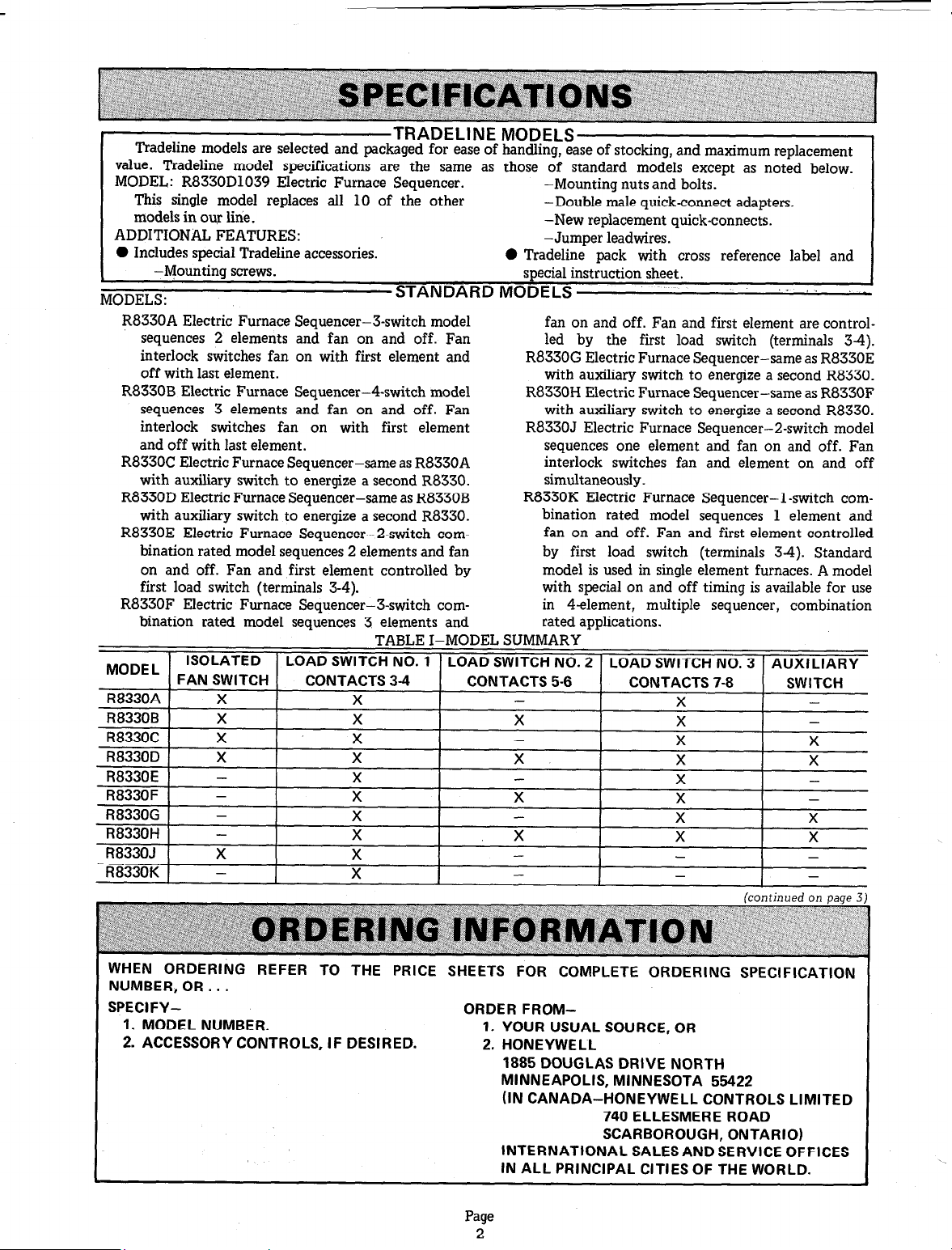
R8330A Electric Furnace Sequencer-3-switch model
sequences 2 elements and fan on and off. Fan
interlock switches fan on with first element and
off with last element.
R8330B Electric Furnace Sequencer-4-switch model
sequences 3 elements and fan on and off. Fan
interlock switches fan on with first element
and off with last element.
R8330C Electric Furnace Sequencer-same as R8330A
with auxiliary switch to energize a second R8330.
R8330D Electric Furnace Sequencer-same as R8330B
with auxiliary switch to energize a second R8330.
R8330E Electric Furnace Sequencer-2-switch com-
bination rated model sequences 2 elements and fan
on and off. Fan and first element controlled by
first load switch (terminals 3-4).
R8330F Electric Furnace Sequencer-J-switch com-
bination rated model sequences 3 elements and
TABLE I-MODEL SUMMARY
-Mounting nuts and bolts.
-Double male quick-connect adapters.
-New replacement quick-connects.
-Jumper leadwires.
0 Tradeline nack with cross reference label and
special instruction sheet.
._
fan on and off. Fan and first element are controlled by the first load switch (terminals 34).
R8330G Electric Furnace Sequencer-same as R8330E
with auxiliary switch to energize a second R8330.
R8330H Electric Furnace Sequencer-same as R8330F
with auxiliary switch to energize a second R8330.
R8330J Electric Furnace Sequencer-2-switch model
sequences one element and fan on and off. Fan
interlock switches fan and element on and off
simultaneously.
R8330K Electric Furnace Sequencer- 1 -switch com-
bination rated model sequences 1 element and
fan on and off. Fan and first element controlled
by first load switch (terminals 34). Standard
model is used in single element furnaces. A model
with special on and off timing is available for use
in 4element, multiple sequencer, combination
rated applications.
I
WHEN ORDERING REFER TO THE PRICE SHEETS FOR COMPLETE ORDERING SPECIFICATION
NUMBER, OR.. .
SPECIFY- ORDER FROM-
1. MODEL NUMBER.
2. ACCESSORY CONTROLS, IF DESIRED.
1. YOUR USUAL SOURCE, OR
2. HONEYWELL
1885 DOUGLAS DRIVE NORTH
MINNEAPOLIS, MINNESOTA 55422
(IN CANADA-HONEYWELL CONTROLS LIMITED
740 ELLESMERE ROAD
SCARBOROUGH, ONTARIO)
INTERNATIONAL SALES AND SERVICE OFFICES
IN ALL PRINCIPAL CITIES OF THE WORLD.
Page
2
Page 3
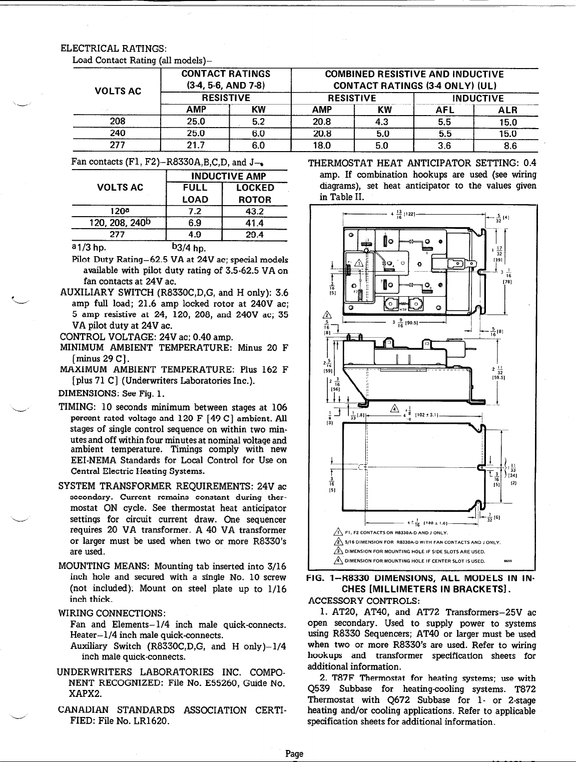
ELECTRICAL RATINGS:
Load Contact Rating (all models)-
CONTACT RATINGS
VOLTS AC
b
208 25.0 5.2 20.8 4.3 5.5 15.0
240 25.0 6.0 20.8 5.0 5.5 15.0
277 21.7 6.0 18.0 5.0 3.6 8.6
(3-4, 5-6, AND 7-8)
RESISTIVE
AMP
KW AMP
Fan contacts (Fl, F2)-R8330A,B,C,D, and J7
COMBINED RESISTIVE AND INDUCTIVE
CONTACT RATINGS (3-4 ONLY) (UL)
RESISTIVE
KW
INDUCTIVE
AFL ALR
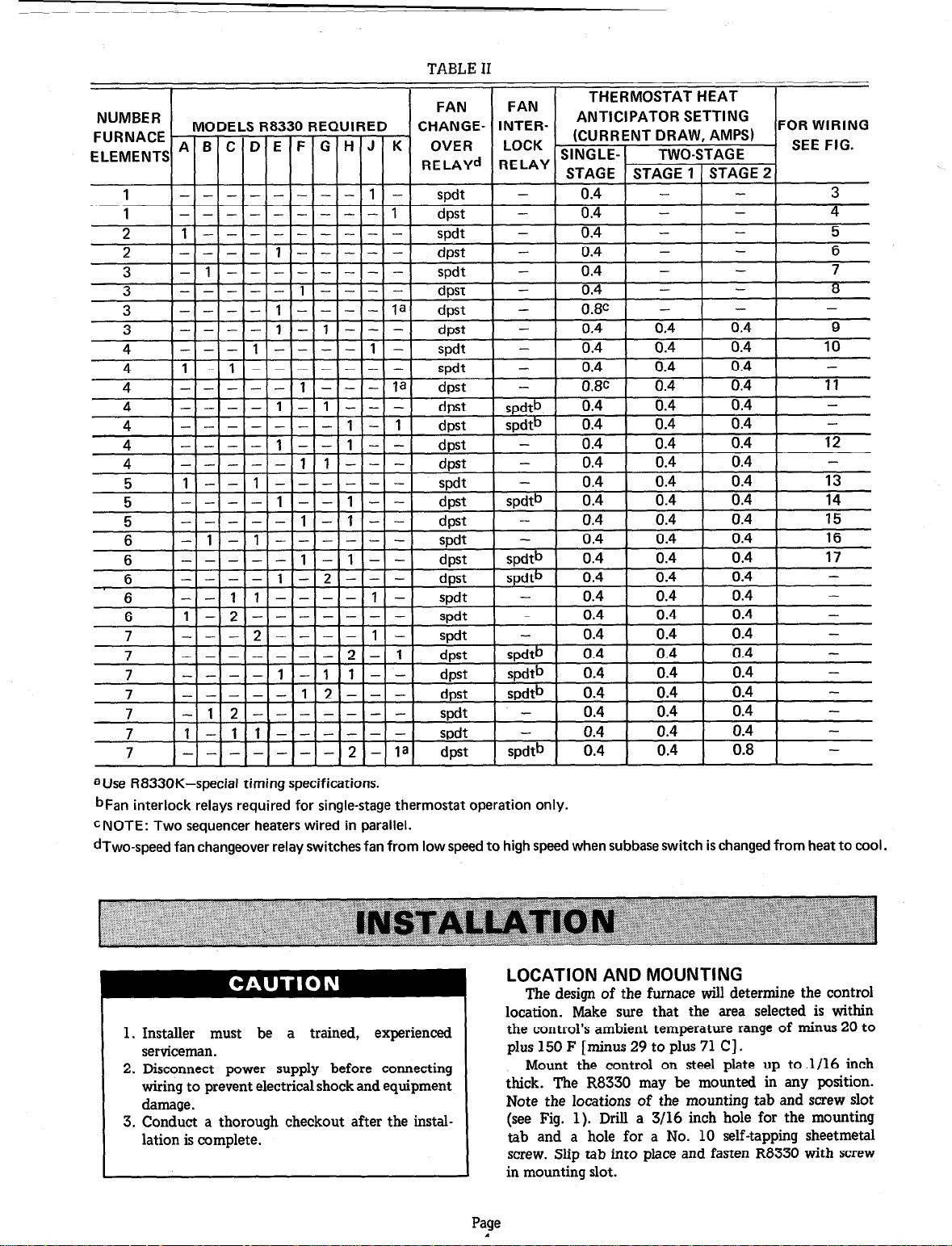
THERMOSTAT HEAT ANTICIPATOR SETTING: 0.4
amp. If combination hookups are used (see wiring
diagrams), set heat anticipator to the values given
in Table II.
I
\-J
ai/3 hp.
b314 hp.
Pilot Duty Rating-62.5 VA at 24V ac; special models
available with pilot duty rating of 3.5-62.5 VA on
fan contacts at 24V ac.
AUXILIARY SWITCH (R8330C,D,G, and H only): 3.6
‘-
amp full load; 21.6 amp locked rotor at 240V ac;
5 amp resistive at 24, 120, 208, and 240V ac; 35
VA pilot duty at 24V ac.
CONTROL VOLTAGE: 24V ac; 0.40 amp.
MINIMUM AMBIENT TEMPERATURE: Minus 20 F
[minus 29 C].
MAXIMUM AMBIENT TEMPERATURE: Plus 162 F
[plus 71 C] (Underwriters Laboratories Inc.).
DIMENSIONS: See Fig. 1.
TIMING: 10 seconds minimum between stages at 106
percent rated voltage and 120 F [49 C] ambient. All
stages of single control sequence on within two minutes and off within four minutes at nominal voltage and
ambient temperature. Timings comply with new
EEI-NEMA Standards for Local Control for Use on
Central Electric Heating Systems.
SYSTEM TRANSFORMER REQUIREMENTS: 24V ac
secondary. Current remains constant during thermostat ON cycle. See thermostat heat anticipator
settings for circuit current draw. One sequencer
requires 20 VA transformer. A 40 VA transformer
or larger must be used when two or more R8330’s
are used.
MOUNTING MEANS: Mounting tab inserted into 3/16
inch hole and secured with a single No. 10 screw
(not included): Mount on steel plate up to l/16
inch thick.
WIRING CONNECTIONS:
Fan and Elements-l/4 inch male quick-connects.
Heater-l/4 inch male quick-connects.
Auxiliary Switch (R8330C,D,G, and H only)-l/4
inch male quick-connects.
UNDERWRITERS LABORATORIES INC. COMPO-
NENT RECOGNIZED: File No. E55260, Guide No.
XAPXZ.
CANADIAN STANDARDS ASSOCIATION CERTI-
FIED: File No. LR1620.
FIG. l-R8330 DIMENSIONS, ALL MODELS IN IN-
CHES [MILLIMETERS IN BRACKETS].
ACCESSORY CONTROLS:
1. AT20, AT40, and AT72 Transformers-25V ac
open secondary. Used to supply power to systems
using R8330 Sequencers; AT40 or larger must be used
when two or more R8330’s are used. Refer to wiring
hookups and transformer specification sheets for
additional information.
2. T87F Thermostat for heating systems; use with
Q539 Subbase for heating-cooling systems. T872
Thermostat with 4672 Subbase for l- or 2-stage
heating and/or cooling applications. Refer to applicable
specification sheets for additional information.
Page
Page 4
4 --
4 --
5 1 5 -5 -6 - 1
6 -6 --
TABLE II
FOR WIRING
7 1
7 -
aUse R8330K-special timing specifications.
bFan interlock relays required for single-stage thermostat operation only.
cNOTE: Two sequencer heaters wired in parallel.
dTwo-speed fan changeover relay switches fan from low speed to high speed when subbase switch is changed from heat to cool.
. _
_ 1 ll- __I- - -
- - -I- -I- 2 -
I
I -r--
_I spdt Ial dpst spdtb
0.4 0.4 0.4 1
0.4 0.4 0.8 1
-
-
LOCATION AND MOUNTING
The design of the furnace will determine the control
location. Make sure that the area selected is within
1. Installer must be a trained, experienced
serviceman.
2. Disconnect power supply before connecting
wiring to prevent electrical shock and equipment
damage.
3. Conduct a thorough checkout after the installation is complete.
the control’s ambient temperature range of minus 20 to
plus 150 F [minus 29 to plus 71 C] .
Mount the control on steel plate up to .1/16 inch
thick. The R8330 may be mounted in any position.
Note the locations of the mounting tab and screw slot
(see Fig. 1). Drill a 3/16 inch hole for the mounting
tab and a hole for a No. 10 self-tapping sheetmetal
screw. Slip tab into place and fasten R8330 with screw
in mounting slot.
?age
1
Page 5

L’
c
rxl9nEl
E
Disconnect power supply to prevent electrical
shock and equipment damage.
I
IMPORTANT
The terminals on these controls are approved for
use with copper wire only.
All wiring must comply with applicable codes and
ordinances. Refer to manufacturer’s wiring information
if available. Terminal identifications are molded in
the R8330 base for wiring convenience. Adjust the
thermostat heat anticipator to match the circuit current
draw (see SPECIFICATIONS).
Figs. 3-17 show typical hookups using the R8330 in
systems with up to six elements. Optional methods of
wiring the fan to provide delayed on and/or off are
shown in Figs. 18-19.
ONE-ELEMENT FURNACES WIRING
R8330A
R8330C
A
AUXILIARY SWITCH
c
QQOQ
660%
R8330E
R8330G R8330H
W-2
AUXILIARY SWITCH
R8330B
R8330D
R8330F
AUXILIARY SWITCH
I PROWDE DlSCONNECT MEANS AND OVERLOAD PROTECTION AS
a
REQUIRED.
2 HEAT ANTlClPATOR SETTING 0.4 AMPS.
n
3 FAN MAY BE WIRED FOR DELAYED ON AND/OR OFF. REFER TO FAN
n
WIRING HOOKUPS. .,a.
FIG. 3-WIRING SCHEMATIC FOR A SINGLE
ELEMENT SYSTEM-ISOLATED FAN.
T87F
ELEMENT 1 :.
POWER + L1
1 SVPPLY + L2
n
PGWER
SUPPLY
A
c L2 -
20 “A
24” TRANSFORMER
f DPST
CHANGEOVER
R8330K 1
ii
R8330J
R8330K
HTR
FIG. P-INTERNAL SCHEMATICS OF R8330 FUR-
NACE SEQUENCERS.
SPEED FAN
I PROVIDE DISCONNECT MEANS AND OVERLOAD PROTECTION AS
n
REQVtRED.
HEAT ANTlClPATOR SETTING 0.4 AMP.
FAN MAY GE WlREO FOR DELAYED ON AND/OR OFF. REFER TO FAN
WlRlNG HOOKUPS.
FIG. 4-WIRING SCHEMATIC FOR A SINGLE-ELE-
MENT SYSTEM-COMBINATION RATED.
Page
.los
Page 6

A
eLI
eL2
TWO-ELEMENT FURNACES
T87F THERMOSTAT
.- - _ _.
\
HTR
Q_P 0-p
Fl
SEQUENCE ON
THERMOSTATCALLS FOR HEAT THERMOSTAT SATISFIED
THERMOSTAT CONTACTS MAKE THERMOSTAT CONTACTS BREAK
I PROVlDE DSCONNECT MEANS AND OVERLOAD PROTECTION AS
A
REQVIREO.
HEAT ANTKIPATOR SETTING 0.4 AMPS.
FAN MAY BE WIRED FOR DELAYED ON AND/OR OFF. REFER TO FAN
OPERATIONAL SEGUENCE
EL%. I ELTT. 2
FAN
w
ELMT. 2
SEQUENCE OFF
EL%. 1
FAN
I
FIG. 5-WIRING SCHEMATIC FOR A TWO-ELEMENT SYSTEM-ISOLATED FAN.
20 “A
24 VOLT
TRANSFORMER
- L1
1
n
FIG. 6-WIRING SCHEMATIC
20 “A
24 VOLT
TRANSFORMER
4
nn
J ~87~ THERMOSTAT
1 PROWOE DISCONNECT MEANS AN0 OVERLOAD PROTEcTION AS
n
REWIRED.
HEAT ANTICIPATOR SETTING 0.4 AMP.
FAN MAY BE WREO FOR OELAYEO ON AND/OR OFF. REFER To FAN
WlRlNG HOOKUPS.
: FOR A TWO-ELEMENT SYSTEM-COMBINATION RATED.
.1,14\
FIG. 7-WIRING SCHEMATIC
1 POWER SUPPLY. PROWOE DISCONNECT MEANS AN0 OVERLOAD
n
PROTECTION AS REQUIRED.
2 FAN MAY BE WREO FOR DELAYED ON AND/OR OFF. REFER TO FAN
a
WlRlNG HOOK”PS.
3 HEAT ANTICIPATOR SETTING 0.4 AMP.
n
4 FOR HEATINO,CO~LING *-SPEED FAN CHANGEOVER, USE SPOT RELAY.
n
FOR HooKuP SEE FIG. 3.
FOR A THREE-ELEMENT SYSTEM-ISOLATED FAN.
Page
A
11158
Page 7

FIG. 8-WIRING SCHEMATIC FOR A THREE-ELEMENT SYSTEM-COMBINATION RATED.
MAKE CONNECTlONS AS SHOWN
FOR IlNcxE STAGE THERMOSTAT;
REMOVE JVMPER FOR &STAGE
THERYOSTAT APPLKATIONS.
40 “A
24 VOLT
LOW VOLTAGE
FURNACE TERMINAL
FURNACE
SEP”ENCER THERMOSTAT SATISFIED SEQUENCER
CwERATlONAL SEwENtE
SEQuErKE on
THEy~;~~;ALLs
THERMOSTAT
CONTACTS MAKE CONTACTS BREAK
SEQUENCEOFF FVRNACE
THERMOSTAT
A”XlLlARY OPENS
FIG. 9-WIRING SCHEMATIC FOR A THREE-ELEMENT SYSTEM-COMBINATION RATED.
Page
7
60-2051-5
Page 8

FOUR-ELEMENT FURNACES
FIG. II-WIRING SCHEMATIC FOR A FOUR-ELEMENT SYSTEM-COMBINATION RATED.
Page
8
Page 9

FIG. 13-WIRING SCHEMATIC FOR A FIVE-ELEMENT SYSTEM-ISOLATED FAN.
Page
9 60-2051
Page 10

FIG. 15-WIRING SCHEMATIC FOR A FIVE-ELEMENT FURNACE-COMBINATION RATED.
Page
10
Page 11

SIX-ELEMENT FURNACES
-
AUXILIARY CLOSES
t
ELMT. 4
R83308 ELMT. 5
{
t
t
ELMT. 6
t
EMT. 6
t
ELMT. 5
t
ELMT. 4
FAN
R83308
)
FIG. 1%WIRING SCHEMATIC FOR A SIX-ELEMENT SYSTEM-ISOLATED FAN.
i
MAKE CONNECTION5 A5 SHOWN FOR
SINGLE STAGE THERMOSTAT APPLICATIONS;
REMOVE JVMPER FOR Z-STAG
THERMOSTAT APP!-ICATIONS.
LOW VOLTAGE FURNACE
TERMINAL BLOCK FOR
THERMOSTAT
OPERATIONAL SEQUENCE
FURNACE
SEPVENCER
R8330H
RBJSOF ELMT. 5 t
SEQUENCE ON
THERMOSTAT CALLS
FOR HEAT
THERMOSTAT
CONTACTS CLOSE
v
ELMT. I
FAN w
FAN INTERLOCK RELAY
w
ELMT. 2
t
ELMT. 3
A”XlLlARY CLOSES
i
{
v
ELMT. 4
w
T
ELMT. 6
THERMOSTAT SATtSFtED SEQUENCER
cotmcx$ BREAK
FAN INTERLOCK RELAY
AUXIUARY OPENS
SEQUENCE OFF FURNACE
THERMOSTAT
ELMT. 3
ELMT. 2
v
ELMT. 1
t
ELMT. 6
w
ELMT. 5
ELMT. 4
FAN
R8330H
>
R8330F
>
\i/
HEAT ANTlClPATOR SETTING 0.4 AMPS.
FIG. 17-WIRING SCHEMATIC FOR A SIX-ELEMENT SYSTEM-COMBINATION RATED.
Page
11
60-2051-5
Page 12

DELAYEI
1 PROWOE ol*CONNECT MEANS AND OVERLOAD PROTECTION
n
AS REQUIRED.
2 FAN ON WlT” FIRST ELEMENT AND REMAINS ON “NT,L FVRNACE
n
COOLS TO FAN CONTROL SET POINT (DELAYED FAN OFF).
IG. l&WIRING SCHEMATIC FOR FAN DELAYED OF
FAN COMES ON WITH FIRST ELEMENT AND
REMAINS ON UNTIL FURNACE COOLS TO FAN
CONTROL SET POINT.
1’11,8
FAI WIRING
T87F
THERMOSTAT
40 “A
24 VOLT
TRANSFORMER
CONTROL
A - I I I
1 PROVlOE DISCONNECT MEANS AND OVERLOAD PROTECTION
n
AS REQUIRED.
2 FAN ON WHEN FURNACE WARMS TO FAN CONTROL SET POINT AND
n
OPERATES UNTIL FURNACE COOLS TO SET POINT (DELAYED FAN ON
AND OFF,.
IG. 19-WIRING SCHEMATIC FOR FAN DELAYED ON AND
OFF. FAN COMES ON WHEN FURNACE WARMS
TO FAN CONTROL SET POINT AND OPERATES
UNTIL FURNACE COOLS TO SET POINT.
-.
*,21m
CHECKOUT
Set the system thermostat to call for heat and make sure that
all elements sequence on and off properly and that fan starts with
first element on and stays on until all elements are off.
NOTE: This is a time delay device; allow time for elements to
sequence on and off.
SERVICE
The R8330 is not field repairable. If any component fails, it
should be replaced. No adjustment or periodic service is required
on these controls. Since all R8330’s are very similar, the R8330D
may be used to replace the R8330A-H or .I.
TROUBLESHOOTING
PRELIMINARY SYSTEM CHECKOUT
1. Check system wiring for any loose or broken connections.
2. Make sure that fan and all heating elements operate
properly.
TRANSFORMER CHECKOUT
1. Use an ac voltmeter to measure the voltage across the
secondary terminals. If voltage is 24V ac 5~ 10 percent, proceed
to check the R8330. If incorrect, proceed to step 2.
2. Check that voltage across transformer primary is within
,+ 10 percent of rated voltage. If correct, replace the transformer.
If the primary voltage is incorrect, correct source problems.
R8330 SYSTEM CHECKOUT
Refer to wiring diagrams. Note that if R8330 Sequencers are
used in combination, the troubleshooting procedure must be
adapted for the individual system.
1. Move the thermostat set point above the room temperature
so that thermostat calls for heat-
a. If system does not start (after time delay), proceed to
step 2.
b. If fan and/or some heating elements start (but not all),
proceed to step 3.
c. If fan and heating elements all sequence on properly,
proceed to step 4.
2. Jumper RH to Wl at the thermostat-
a. If fan and heating elements now begin operating (after
time delay), check thermostat and wiring and replace
thermostat if necessary. Proceed to step 4.
b. If neither fan nor heating elements operate (and system
wiring has been checked), replace the R8330.
3. Jumper across the terminals of the Inoperative fan or
heating element. If the fan or element now starts, the contacts
are not conducting; replace the R8330.
The R8330 contacts carry line voltage.
4. When all elements and fan are on, break the power supply
to the R8330 by lowering the thermostat set point (or removing
jumper RH-Wl) so that switch breaks. Check to make sure that
all heating stages sequence off, beginning with the last element on.
The fan should operate until all stages are off, turning off with the
last stage.
NOTE: This is a time delay device; allow time for all elements
to sequence off.
HONEYWELL MINNEAPbIS, MINN. 55408 INTERNATIONAL Sales Offices in all principal cities of the world. Manufacturing in Australia, Canada, Finland, France, Germany, Japan,
Mexico, Netherlands, Spain, Taiwan, United Kingdom, U.S.A.
PRINTED IN U.S.A.
 Loading...