

Page 1
RADELINE
®
R8285A,B
Control Centers
Application
R8285A,B Control Centers provide low voltage control
of line voltage fan motors and auxiliary circuits in heating,
TABLE 1—R8285 MODEL SPECIFICATIONS.
Control Replacement
Center Relay
R8285A R8222B 12 60 spdt 120 or 208/240 Fig. 1
R8285B R8222D 12 60 dpdt 120, 208/240, or 120/208/240 Fig. 2
The R8285A has spdt switching for two-speed fan mo-
tor applications.
The R8285B has dpdt switching for Total Comfort
applications with electronic air cleaner, humidifier, and
blower motor.
CONTACT RATINGS: Refer to Table 2.
TABLE 2—R8285A,B CONTACT RATINGS.
Voltage 120 Vac 208/240 Vac
Full Load (amp) 12 6
Locked Rotor (amp) 60 35
a
Meets UL 3/4 horsepower requirements.
RELAY COIL RATINGS:
Inrush: 20 VA maximum.
Sealed: 9 VA nominal.
Wattage: 5 watts.
Pickup Voltage: Must pick up below 18 volts.
TRANSFORMER RATINGS:
Power Rating: 40 or 50 VA.
Primary Voltage: 120, 208/240, or 120/208/240 Vac.
Secondary Voltage for 40 VA at 1.67 Amps: 24 Vac.
Secondary Voltage for 50 VA at 2.08 Amps: 24 Vac.
Open Circuit Secondary Voltage: 27.0.
Overload Protection: Inherent.
Voltage Frequency: 60 Hz.
Contact Rating
AFL ALR
a
cooling, or air conditioning systems. For model specifications, refer to Table 1.
Switching Input Voltage (Vac) Diagram
Installation
WHEN INSTALLING THIS PRODUCT…
1. Read these instructions carefully. Failure to follow
them could damage the product or cause a hazardous condition.
2. Check the ratings given in these instructions and on
the product to ensure the product is suitable for your
application.
3. Ensure installer is a trained, experienced service
technician.
4. After completing installation, use these instructions
to check product operation.
CA UTION
Disconnect power supply before beginning installation to prevent electrical shock and equipment
damage.
MOUNTING
The R8285 mounts on a standard four inch square
junction box. Make wiring connections in the junction box,
then fasten the R8285 to the junction box by placing the
junction box screws through the notches in the R8285
mounting plate.
See Wiring
1 69-0482—2J. H. • 4-94 • ©Honeywell Inc. 1994 • Form Number 69-0482—2
Page 2
NOTE: The R8285 must be mounted in an enclosure. The
R8285 may be mounted in any position except with the
mounting plate horizontal and the relay on top of the
mounting plate.
WIRING R8285A, B MODELS
All wiring must comply with local codes and ordinances. Disconnect power before making wiring connections to prevent electrical shock or equipment damage.
1. Make primary connections to line voltage power
supply. On multitap models, make sure you are using
correct leads or terminals for available power supply. See
Fig. 1.
2. On multitap models with leadwires, insulate ends of
unused leads by taping or capping with a solderless connector.
3. Make secondary connections to 24 Vac control circuit.
4. Refer to Figs. 2 or 3 for typical wiring diagrams.
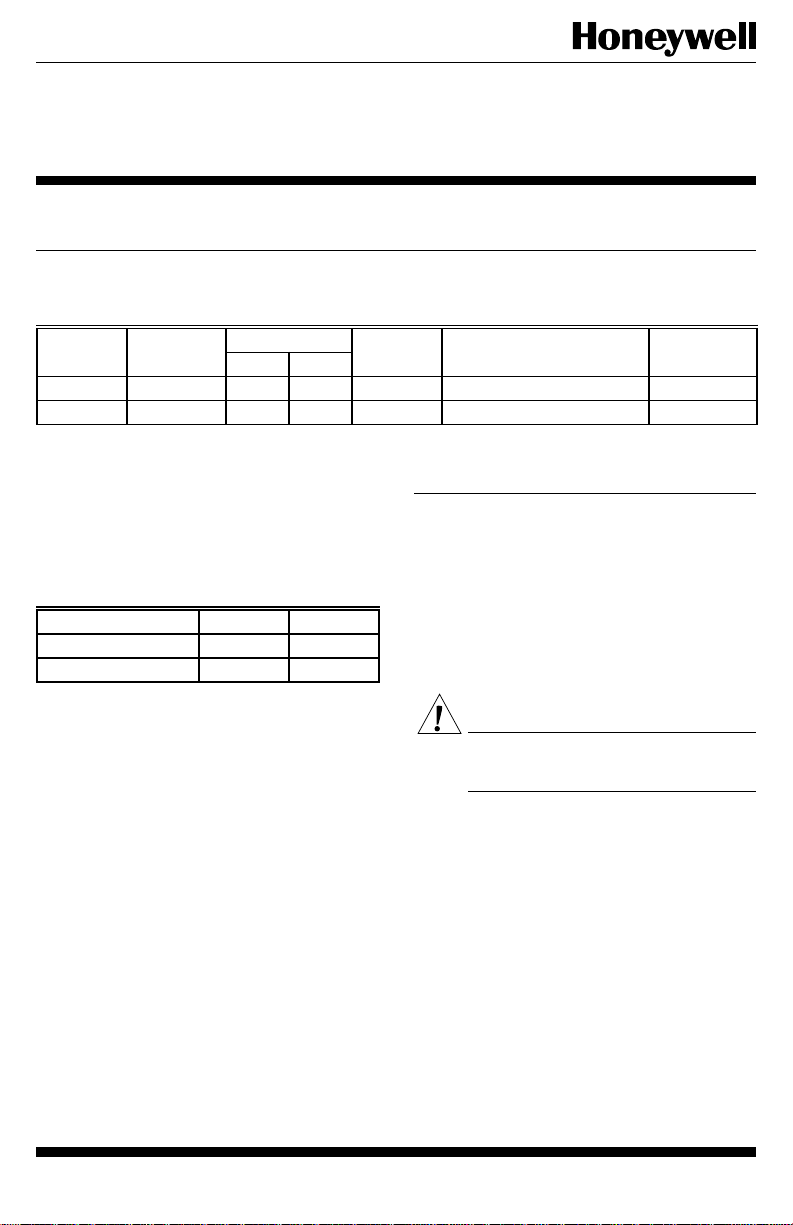
Fig. 1—Schematic for single and multitap
transformers.
120 VAC MODELS
2
COMMON
BLACK
PRIMARY
120 V
3
120V - WHITE
1
SECONDARY
208/240 VAC MODELS
2
BLACK
RED
ORANGE
1
SECONDARY
PRIMARY
3
COMMON
208V
240V
120/208/240 VAC MODELS
COMMON
PRIMARY
3
1 SECONDARY CONNECTIONS ARE SCREW TERMINALS, 1/4 INCH
QUICK-CONNECTS OR BLUE AND YELLOW LEADWIRES.
2
BLACK IS COMMON WITH RESPECT TO THE TRANSFORMER
WINDING ONLY AND NOT THE EXTERNAL CIRCUIT.
SOME MODELS AVAILABLE WITH 1/4 INCH QUICK-CONNECTS.
3
120V
208V
240V
2
BLACK
WHITE
RED
ORANGE
1
SECONDARY
M21020
IMPORTANT: Only use Underwriters Laboratories Inc.
listed connectors when making external circuit connections to the line voltage leadwires of this device.
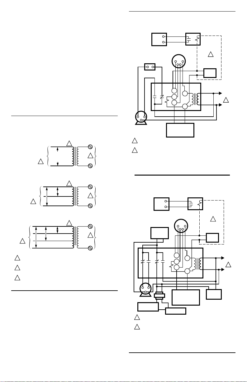
Fig. 2—R8285A typical hookup in two-speed
fan motor application.
R8225 ISOLATION
COIL
BLACK
R8285B
RELAY
THERMOSTAT
W
R
GGY
W
Y
CONTACTOR OR
COMPRESSOR
CONTROL PANEL
R882A ISOLATION
RELAY
T87F
THERMOSTAT
W
GGY
W
COIL
Y
RED/
YELLOW
R8243
CONTACTOR OR
COMPRESSOR
CONTROL PANEL
HUMIDIFIER
PRIMARY
HEATING
CONTROL
R8285A,H
BLACK
R
WHITE
C
application.
R
BLACK
R
WHITE
C
2
2
PRIMARY
HEATING
CONTROL
FAN
SWITCH
HEATING
CONTROL
PLENUM SWITCH
OR OTHER
SWITCHING DEVICE
BROWN
RED
LO
HI
C
TWO SPEED
FAN MOTOR
POWER SUPPLY. PROVIDE DISCONNECT MEANS AND OVERLOAD
1
PROTECTION AS REQUIRED.
2
USE OPTIONAL HOOKUP WITH ISOLATING RELAY (DASHED LINE) IF
HEATING CONTROL HAS A SEPARATE POWER SUPPLY. ISOLATION
OF THE POWER SUPPLIES MAY ALSO BE ACCOMPLISHED BY USING
SPECIAL THERMOSTAT SUBBASE COMBINATIONS WITH ISOLATED
CIRCUITS (SUCH AS T87F-Q539A1147, T834A, T822A).
REFER TO SPECIFICATION SHEETS FOR DETAILS.
Fig. 3—R8285B typical hookup in two-speed
fan motor
COM
1
2
Total Comfort
HEATING
CONTROL
F50 OR F51
AIR CLEANER
BW
BLACK
VIOLET
RED
BROWN
YELLOW
HI
LO
H808A
HUMIDISTAT
POWER SUPPLY. PROVIDE DISCONNECT MEANS AND OVERLOAD
PROTECTION AS REQUIRED.
USE OPTIONAL HOOKUP WITH ISOLATING RELAY (DASHED LINE) IF
HEATING CONTROL HAS A SEPARATE POWER SUPPLY. ISOLATION
OF THE POWER SUPPLIES MAY ALSO BE ACCOMPLISHED BY USING
SPECIAL THERMOSTAT SUBBASE COMBINATIONS WITH ISOLATED
CIRCUITS (SUCH AS T87F-Q539A1147, T834A, T822A).
REFER TO SPECIFICATION SHEETS FOR DETAILS.
L1
(HOT)
L2
M1157B
M1153C
1
L1
(HOT)
1
L2
69-0482—22
Page 3

Checkout
Always conduct a thorough checkout when installation
is complete. Operate the system through at least one complete cycle to assure that the system equipment and the
R8285 operate as intended.
Service
CA UTION
Disconnect the power supply before servicing to
prevent electrical shock and equipment damage.
The R8285 relay is field replaceable. Replace the relay
as follows:
1. Refer to Table 1 for the appropriate replacement
relay.
2. Remove the plug-in relay from the receptacle and
replace with the new relay. See Fig. 4.
Fig. 4—Replacing R8285 relay.
RECEPTACLE
R8222 RELAY
RETAINING BAIL
M1298
3 69-0482—2
Page 4

Home and Building Control Home and Building Control Helping You Control Your World
Honeywell Inc. Honeywell Limited—Honeywell Limitée
1985 Douglas Drive North 740 Ellesmere Road
Golden Valley, MN 55422 Scarborough, Ontario
M1P 2V9
69-0482—24
Printed in U.S.A.
QUALITY IS KEY
 Loading...