

Page 1
60-0014-07
R4222A-H,J-N,P-W,Y; R8222A-H,
CAUTION
1
2
3
4
5
6
1-42/64 (41.6)
1-55/64
(47.2)
2-7/64 (53.5)
2-3/64 (51.9)
2-1/4 (57.2)
2-3/8 (60.3)
M13955
J-N,P-W,Y,Z; R4228A,B,C,D;
R8228A,B,C,D
SWITCHING RELAYS
INSTALLATION INSTRUCTIONS
APPLICATION
The R4222 and R8222 are general purpose relays for use
in refrigeration and air conditioning equipment, vending
machines, and other applications requiring general
purpose switching. R4228 and R8228 are heavy-duty
relays with the same application.
A variety of switching configurations are available. Refer
to Tables 1 and 2. Contacts are available for Powerpile
(millivoltage), pilot duty, and power pole applications.
R4222 and R4228 models have line voltage; R8222 and
R8228 models have low voltage coils.
INSTALLATION
1 Installer must be a trained, experienced
service technician.
2 Disconnect power supply before beginning
installation.
3 Always conduct a thorough checkout when
installation is complete.
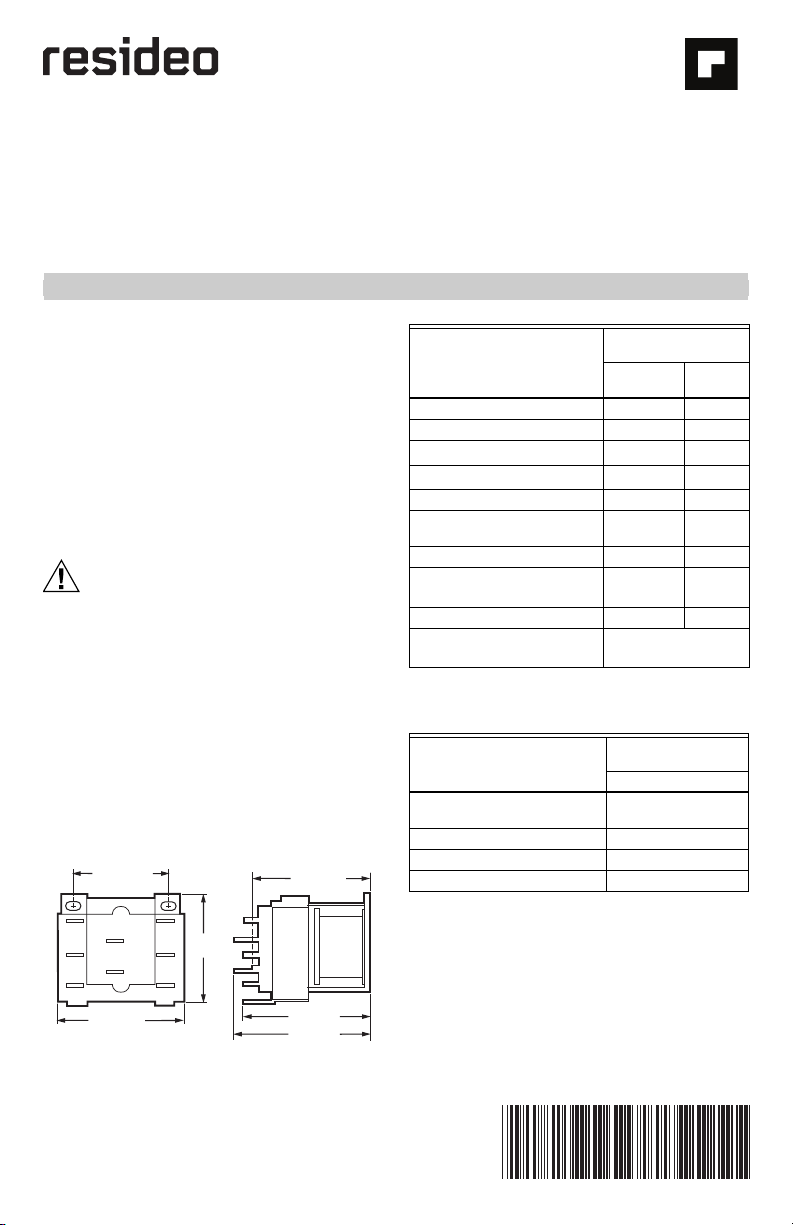
LOCATION
Mount the relay on a flat, solid surface as close as
possible to the equipment being controlled. The relay
may be mounted in any position except with the
terminals pointed down. Secure in place with two
screws through holes or slots in the mounting base. See
Fig. 1 for mounting dimensions.
Fig. 1. Dimensions in inches (millimeters in brackets).
Table 1. Switching configurations for R4222 and R8222
Contact configurations (coil
de-energized)
Spst, normally open A K
Spdt B L
Dpst, normally open
c
Dpdt
Spst, normally closed E P
Dpst, one normally open and
one normally closed
Dpst, normally closed G R
Spdt and spst, normally
d,e
open
Spdt and spst, normally closed J T
Dpst, normally dosed (one
power and one pilot duty)
*Models with silver colored power terminals and brass
colored pilot duty terminals.
Table 2. Switching configurations for R4228 and R8228
Contact configurations (coil
de-energized)
Spst, normally open (double
quick-connects)
Spdt (double quick-connects) B
Spst, normally open C
Dpst, normally open D
a
Refer to Fig. 2 for terminal location and identification.
b
R4222U, R8222U available with one pilot duty pole and
one power pole.
c
R4222V, R8222V available with one power pole and one
pilot duty rating.
d
W model available with spdt power pole and spst pilot
duty pole.
e
Y model available with spdt pilot duty pole and spst
power pole.
f
Z model available with spst power pole and spst pilot
duty pole.
a
b
a
f
R4222, R8222 suffix
letters
Power pole
rated
R4228, R8228 suffix
Pilot duty
rated
CM
DN
FQ
HS
Z*
letters
Power pole only
A
Page 2
R4222A-H,J-N,P-W,Y; R8222A-H, J-N,P-W,Y,Z; R4228A,B,C, D; R8228A,B,C,D
.
1
4
COIL
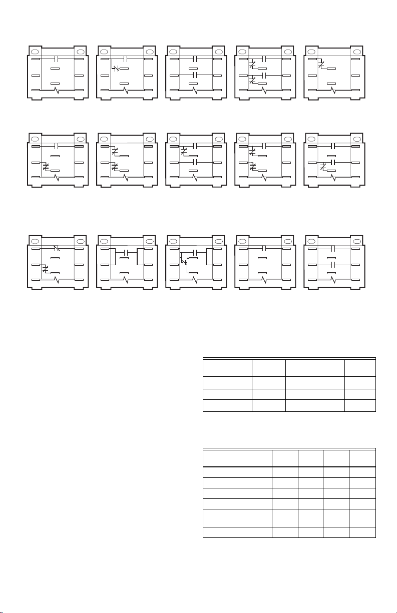
R4222A,K/R8222A,K
SPST, NORMALLY OPEN
1
4
COIL
R4222F,Q/R8222F,Q
DPST, ONE NORMALLY OPEN
AND ONE NORMALLY CLOSED
(EXCEPT FOR R4222Q1097 WHICH
HAS REVERSE TERMINAL
IDENTIFICATION
1-2 IS N.C. 4-5 IS N.O.)
1
4
COIL
R8222Z
DPST, NORMALLY CLOSED
3
2
5
2
5
2
5
1
6
4
R4222B,L/R8222B,L
SPDT
3
1
6
4
R4222G,R/R8222G,R
DPST, NORMALLY CLOSED
3
1
6
4
R4228A/R8228A
SPST, NORMALLY OPEN
(DOUBLE QUICK CONNECT)
COIL
COIL
COIL
3
2
5
2
5
2
5
1
6
4
R4222C,M,U/R8222C,M,U
DPST, NORMALLY OPEN
3
1
6
4
R4222H,S,W/R8222H,S,W
SPDT AND SPST,
NORMALLY OPEN
3
1
6
4
R4228B/R8228B
SPDT,
(DOUBLE QUICK CONNECT)
COIL
COIL
COIL
Fig. 2. R8222/R422, R8228/R4228 circuit and terminal identification.
WIRING
Disconnect power supply before making wiring
connections to prevent possible electric shock and
equipment damage.
All wiring must comply with local codes and ordinances.
Crimp female quick connects to the system wires and
attach to the male quick connect terminals of the relay.
The relay has molded terminal numbers and a circuit
diagram for easy identification when wiring. Fig. 2 shows
the terminal location and circuits of all models.
Do not exceed contact and coil ratings when wiring into
the system.
Contact ratings
R4222 and R8222 contacts are available for pilot duty,
power pole, or millivoltage applications. R4228 and
R8228 contacts have power pole ratings only. See
Tables 3 and 4.
3
6
R4222D,N,V/R8222D,N,V
DPDT
3
6
R4222J,T/R8222J,T
SPDT AND SPST,
NORMALLY CLOSED
3
6
R4228C/R8228C
SPST, NORMALLY OPEN
1
4
COIL
1
4
COIL
1
4
COIL
2
5
2
5
2
5
3
2
5
2
5
2
5
1
6
4
R4222E,P/R822E,P
SPST, NORMALLY CLOSED
3
1
6
4
R4222Y/R8222Y
SPDT AND SPST,
NORMALLY OPEN
3
1
6
4
R4228D/R8228D
DPST, NORMALLY OPEN
2
5
COIL
2
5
COIL
2
5
COIL
M13956
Table 3. Power poles for R4222 and R8222 (per pole,
amperes)
R4222, R8222 120 Vac
a
Full load
208/240 Vac, 277
Vac 480 Vac
12 6 3
Locked rotor 60 36 18
b
Resistive
a
Also rated 1/2 hp at 120, 240, and 480 Vac.
b
0.75 power factor load.
15 15 10
Table 4. Contact ratings for R4228, R8228
R4228A,B and
R8228A,B 120 Vac 240 Vac 277 Vac 480 Vac
Full load 16 12 5
Locked rotor 96 72 30
Horsepower 1 2 1–1/2
Resistive 25 15
R4228C,D and
R8228C,D
Resistive only 25 10
3
6
3
6
3
6
69-0014—07 2
Page 3

R4222A-H,J-N,P-W,Y; R8222A-H, J-N,P-W,Y,Z; R4228A,B,C,D; R8228 A,B,C,D
Pilot duty poles for R4222 and R8222 only
Minimum: 3 VA at 24, 120, 240, and 480 Vac.
Maximum: 25 VA at 24 Vac; 125 VA at 120, 240, and 480
Vac.
Resistive: 3 amps at 480 Vac (0.75 power factor).
Millivoltage: Available upon request with standard milli-
voltage ratings. Contact your local Resideo representative for additional information.
Coil Ratings
All coils meet Underwriters Laboratories Inc. requirements for Class B coils. If coil voltages other than
those listed in Table 5 are desired, contact your local
Resideo representative for additional information.
Table 5. Coil ratings for R4222, R4228, R8222, and
Inrush VA
(maximum)
Sealed VA
(maximum)
Current draw 0.4 –
Pickup voltage: 75 percent of rated call voltage.
a
Coils are rated for 50/60 Hz. Data is at 60 Hz.
R8228
120, 208/240, 277, 480
a
24 Vac
20 20
9.5 10
Vac
a
ACCESSORIES
1. 135959 receptacle only.
2. 135887 bail only.
CHECKOUT
Operate the relay and controlled equipment to make sure
that the relay pulls in when the coil is energized and that
the controlled equipment operates as intended.
3 69-0014—07
Page 4

R4222A-H,J-N,P-W,Y; R8222A-H, J-N,P-W,Y,Z; R4228A,B,C, D; R8228A,B,C,D
Resideo Technologies, Inc.
1985 Douglas Drive North, Golden Valley, MN 55422
www.resideo.com
© 2020 Resideo Technologies, Inc. All rights reserved.
This product is manufactured by Resideo Technologies, Inc. and i ts affiliates.
1-800-468-1502
69-0014—07 M.S. Rev. 05-20 | Printed in United States
 Loading...