

Honeywell Q7055C Installation Instructions Manual
Q7055C Building Network Adapters
WARNING
BNA-1C/2CS
INSTALLATION INSTRUCTIONS
— Q7055C1009 BNA-1C. Provides a single RS-485 DC
This equipment generates, uses and can radiate
radio frequency energy, and if not installed and
used in accordance with the Instructions Manual,
may cause interference with radio communication.
It has been tested and found to comply with the
limits for a Class A computing device pursuant to
Subpart J of Part 15 or FCC Rules, which are
designed to provide reasonable protection against
such interference when operated in a commercial
environment. Operation of this equipment in a
residential area is likely to cause interference, in
which case, users at their own expense will be
required to take whatever measures may be
required to correct the interference. Any
unauthorized modification of this equipment may
result in the revocation of the owner's authority to
continue its operation.
coupled C-Bus-compatible communication channel for
Excel 5000
— Q7055C1017 BNA-2CS. Provides two RS-485 DC
coupled C-/S-Bus compatible communication channels for Excel Classic and XL5000 family devices in
smoke control systems with up to 76.8 kbps.
Additionally, each BNA is equipped with a RJ-45 10/100BaseT
connector, plus an RS-232 interface. (see Fig. 1).
®
family devices with up to 76.8 kbps.
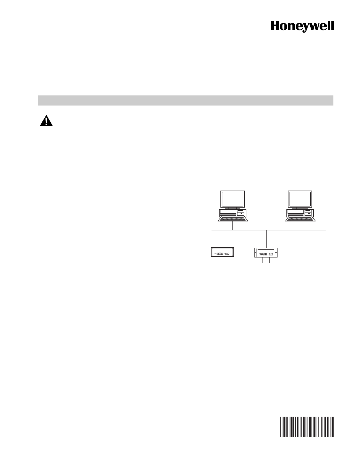
WO RKS TATIO N
EBI
ETHERNET
LOCAL AREA NETWORK
WORKSTATION
GENERAL
The Q7055C series Building Network Adapters (BNA) provide
connection of a Honeywell
an industry standard 10/100BaseT Ethernet LAN. The
Building Network Adapter (BNA) delivers exceptional price/
performance to meet the requirements of both building owners
and service providers. With its combination of scalable
performance, density, and low per-port pricing, the BNA
allows network-layer capabilities to be extended to a much
wider range of network configurations and environments.
High-performance network and services, including traffic
management, are now available to additional locations
throughout the network.
The BNA uses the LAN-connection to provide a seamless
communication to the requesting device. Status information
such as LAN communication activity, field bus traffic
communication, and system Heartbeat of the BNA is indicated
by LEDs on the front of the device.
The BNA models provide an interface from various Honeywell
controller buses that use RS-485 signals to a local area
network using 802.3 Ethernet protocol. This allows data to be
used by high-level Building Management Systems such as the
Honeywell Enterprise Buildings Integrator (EBI)
This Installation Instruction covers the following BNA devices:
®
controller communication bus to
™
.
BNA-1C
SINGLE C-BUS
(ONLY FOR XL5000, IRC AND EMC
CONTROLLERS FAMILIES)
The Q7055C Building Network Adapter is used in systems for
signaling smoke control of fire (UL 864-9th), UL 916, and
general purpose signaling (UL 2017). Also applies to CEC
22.1 standard. In UL 2017 applications, the product can be
used as either a type SM (Self-Monitored) or type AM
(Attendant-Monitored) system.
EMC, EXCEL CLASSIC
CONTROLLERS FAMILIES)
Fig. 1. BNA network.
BNA-2CS
TWO C-/S-BUS
(FOR EXCEL IRC,
AND XL5000
M25320
SPECIFICATIONS
Models:
Q7055C1009 Building Network Adapter BNA-1C. Provides a
single RS-485 DC coupled C-Bus-compatible
communication channel for XL800 and Excel 5000 family
devices with up to 76.8 kbps.
95-7735
Q7055C BUILDING NETWORK ADAPTERS BNA-1C/2CS
CAUTION
Q7055C1017 Building Network Adapter BNA-2CS. Provides
two RS-485 DC coupled C-/S-Bus compatible
communication channels for Excel Classic, Excel 800, and
XL5000 family devices.
Electrical Ratings:
Supply Voltage: 24 VAC, 50 to 60 Hz, or 24 VDC (external
power supply required).
Power Consumption: BNA-1C: 8 VA. BNA-2CS: 8 VA.
Temperature Ratings:
Operating: 32° F to 122° F (0° C to 50° C).
Storage: -13° F to +185° F (-25° C to +85° C).
Humidity Ratings: 5 to 93% RH, non-condensing.
System Data:
Processor: 32-bit high-speed microprocessor.
Data Transfer: 10/100 Mbit/sec., 802.3 Ethernet.
LAN Interface: 10/100BaseT (RJ-45).
Field Bus (-1C/-2CS): RS-485 DC coupled XL5000 C-/S-Bus.
Device Interface: Serial RS-232.
Memory: SDRAM, NOR & NAND Flash
MTBF: > 100,000 hours.
Safety:
Protection Standard: IP20 according to EN60529.
Protection Class: II according to EN60730-1.
Flame Retardant: V0 according to UL 94.
Dimensions: 2-13/16 in. (72 mm) high x 8-13/16 in. (224 mm)
wide x 7-13/16 in. (199 mm) deep.
Weight: 2.0 lb. (0.9 kg).
Approvals:
BNA-1C/2CS:
Electromagnetic Compatibility (EMC): EN50081-1 and
EN50082-2.
Electromagnetic Emission (EME): FCC Class A.
Energy Management: UL 916 PAZX.
Fire Protection and Smoke Control: UL 864, UUKL; Miscel-
laneous Signaling UL2017 QVAX.
Additional Equipment:
DC Power Supply: 50017367-001 Jameco
®
Model No.
DDU240050, 120 VAC, 60 Hz 15 VA input, 24 VDC, 0.500
Amp output, wall mounted power cube Class 2 (included).
AC Power Supply: 120 VAC/50 to 60 Hz input, 24 V AC output,
14507287 series.
Mounting: 14006090-555151 series communication panels.
14507678-004 Ditek Ethernet Port Surge Protector.
14502412-014: Lightning Protector.
— Building Network Adapter device.
— 50017367-001 Power Supply.
— Building Network Adapter Installation Instructions.
— Bag of installation materials as follows: one 3-pole
Phoenix power connector, one or two Phoenix controller bus channel connectors, four optional wall
mounting clips, four small inserts and four screws.
4. Read the Connections section carefully prior to connecting power, ground and data interface cables to the BNA.
5. Refer to the installation instructions for each component
connected to the BNA:
— Form no. 95-7481, Excel 100, 500, 600 Series
Controller Sub panel Installation Instructions.
— Form no. 95-7524, Excel 500/600 Control System
Installation Instructions.
— Form no. 95-7551, EBI LAN Interface Installation
Instructions.
— Form no. 95-7705, EBI LAN Interface Installation
Instructions.
WIRING
Shock Hazard. Removal of the BNA cover can
result in electrical shock.
Do not remove cover. There are no user serviceable
parts inside.
Location and Mounting
The BNA device is intended for installation only indoors in a
dry location. It can be mounted in several ways; as a single
device, up to three stacked devices, or wall/cabinet mounted.
NOTE: Stacking of BNA devices is not recommended for
smoke control applications.
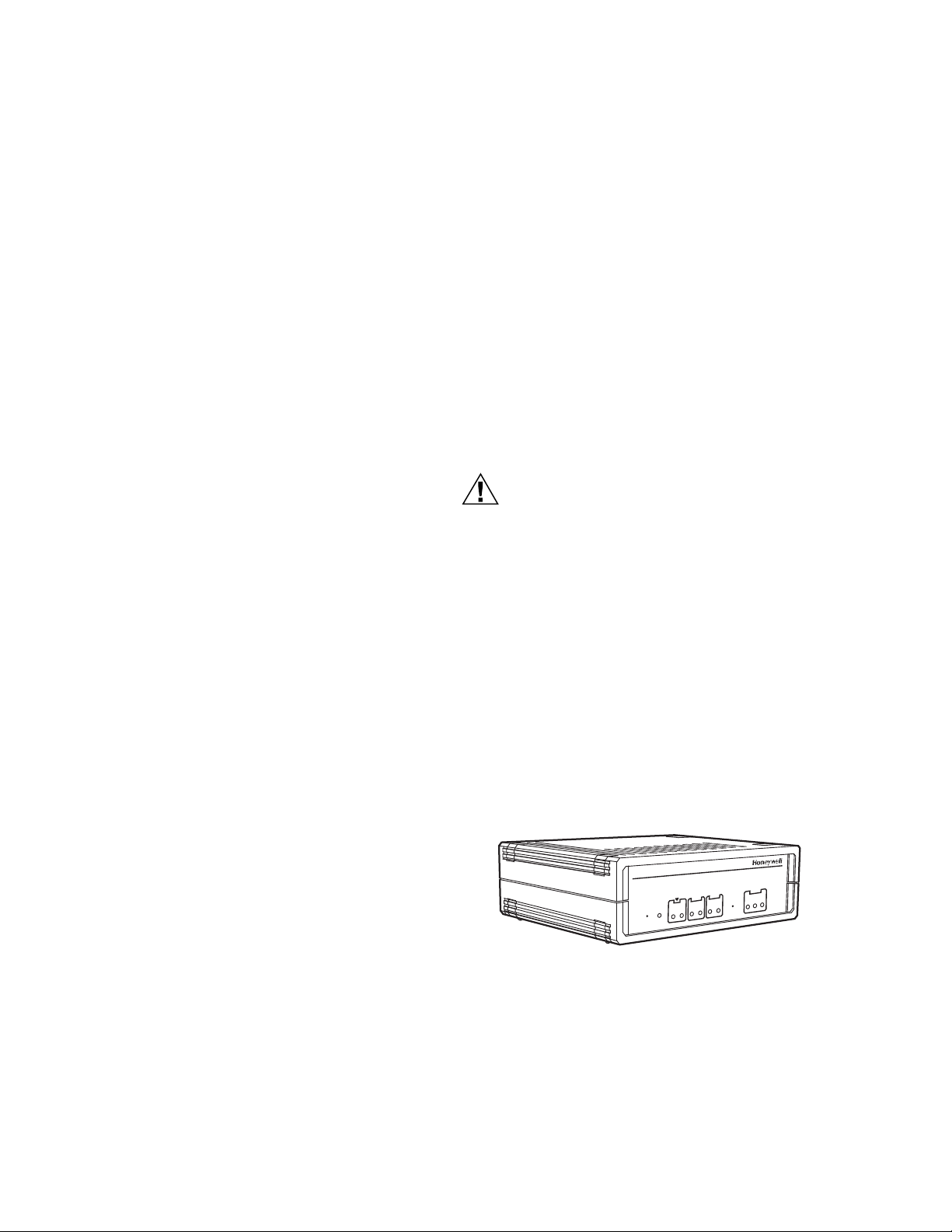
Single Device
The following illustration shows the single BNA device
operating position; for example, on a desk (see Fig 2).
2CS
BUILDING NETWORK ADAPTER M
Reset Power
ODEL
LAN
Ch2
Ch1
Rx
Tx
Rx
NML
Boot
ACT
100
10
Mode
Tx
M22586
BEFORE INSTALLATION
Perform the following steps prior to installing the BNA device
1. Verify that the product has been received without damage.
2. Verify that the correct BNA device has been delivered.
3. Check the package contents. The following items are
included in each product package:
95-7735 2
Fig. 2. Single Device Operating Position.
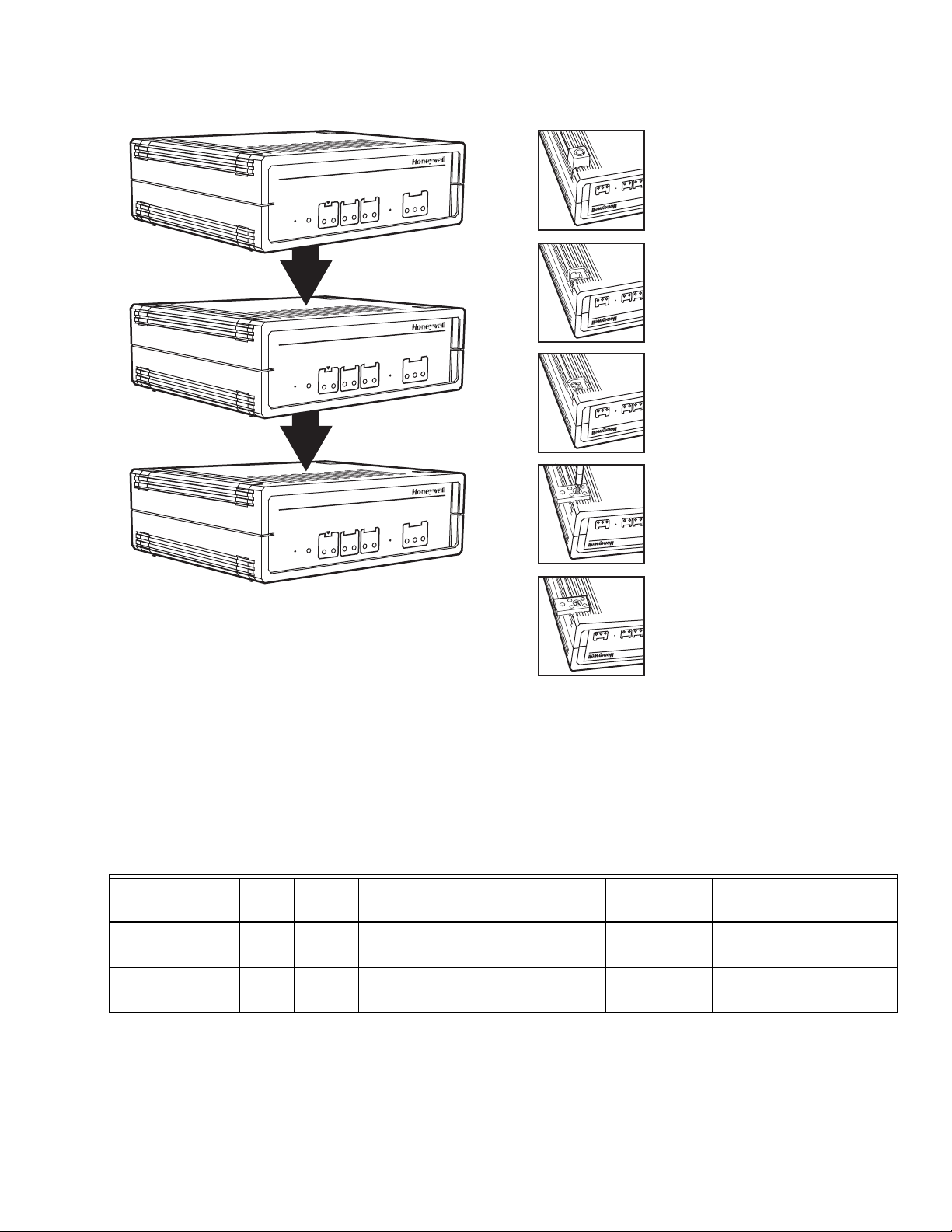
Stacked Devices
BNA devices may also be stacked except in smoke control
applications. Because of stability issues, it is recommended
not to stack more than three devices (see Fig 3).
NOTE: There are cooling slots on the top and bottom of the
BNA housing.
BUILDING NETWORK ADAPTER M
588
Reset Power
BUILDING NETWORK ADAPTER M
Reset Power
BUILDING NETWORK ADAPTER M
Reset Power
Ch1
Rx
NML
Boot
Ch1
Rx
NML
Boot
Ch1
Rx
NML
Boot
Q7055C BUILDING NETWORK ADAPTERS BNA-1C/2CS
Place the BNA-adapter with the topside
2CS
ODEL
10
100
ACT
LAN
Ch2
Tx
Rx
Tx
2CS
ODEL
Ch2
Tx
Rx
Tx
2CS
ODEL
Ch2
Tx
Rx
Tx
ACT
100
10
Mode
LAN
ACT
100
10
Mode
LAN
ACT
100
10
Mode
LAN
10
100
ACT
LAN
10
100
ACT
LAN
10
100
ACT
LAN
down on the desk.
Rx
Tx
Rx
Tx
Ch2
Ch1
Mode
Remove the four feet from the bottom of
the BNA by pushing horizontally away from
the housing with a flat screwdrive r .
Rx
Tx
Rx
Tx
Ch2
Ch1
Mode
Push the four inserts (included) fully and
horizontally into the housing.
Rx
Tx
Rx
Tx
Ch2
Ch1
Mode
Adjust the four retaining clips (included) on
top of the inserts. Fasten the retaining clips
with the included four screws.
Rx
Tx
Rx
Tx
Ch2
Mode
Ch1
M25115
Use the housing with the clips to mark the
positions of the four mounting holes on the
Fig. 3. Stacked Devices.
10
100
ACT
Mode
LAN
wall surface. Drill 1/8 in. (3 mm) holes for
the mounting screws (not included) and fix
Rx
Tx
Rx
Tx
Ch2
Ch1
the BNA device.
Wall Mounting
It is also possible to mount the BNA device to a wall. The
following sequence describes how the device should be
prepared prior to mounting it on a wall (see Fig 4). Fig. 4. BNA wall mount.
Communications Panel Mounting
It is also possible to mount the BNA device in the 14006090555151 series Communications Panel (see Fig. 5). This
method of mounting is recommended for smoke control
applications.
Table 1. C-Bus Connector Terminal Specifications.
Connector
Terminal Pin
CH1/CH2 RS-485
(C-BUS)*
CH1/CH2 RS-485
(C-BUS)*
A(+) +In Input/Output SIGNAL ±5 V 1 mA/ 180 mA 9600 baud 100 ohms
B(-) -In Input/Output SIGNAL ±5 V 1 mA/ 180 mA 9600 baud 100 ohms
Signal
Type
Input/
Output
Voltage
Type
Max.
Voltage Max. Current
Max.
Frequency
M22
A
Max.Line
Impedance
* supervised spaces Max wiring distance 4,000 ft. (1,219m), 18AWG min.
3 95-7735
 Loading...