

Page 1
Q7055B1047
Open View Net Server (OVN)
This INSTALLATION INSTRUCTIONS document covers the
WARNING
This equipment generates, uses and can radiate
radio frequency energy, and if not installed and
used in accordance with the Instructions Manual,
may cause interference with radio communication.
It has been tested and found to comply with the
limits for a Class A computing device pursuant to
Subpart J of Part 15 or FCC Rules, which are
designed to provide reasonable protection against
such interference when operated in a commercial
environment. Operation of this equipment in a
residential area is likely to cause interference, in
which case, users at their own expense will be
required to take whatever measures may be
required to correct the interference. Any
unauthorized modification of this equipment may
result in the revocation of the owner's authority to
continue its operation.
following OVN server:
— Q7055B1047. Provides a single RS-485 DC coupled
C-Bus compatible communication channel for as many as
six Excel 5000™ family devices with up to 76.8 kbps and
single RS-232 and 10/100BaseT interfaces.
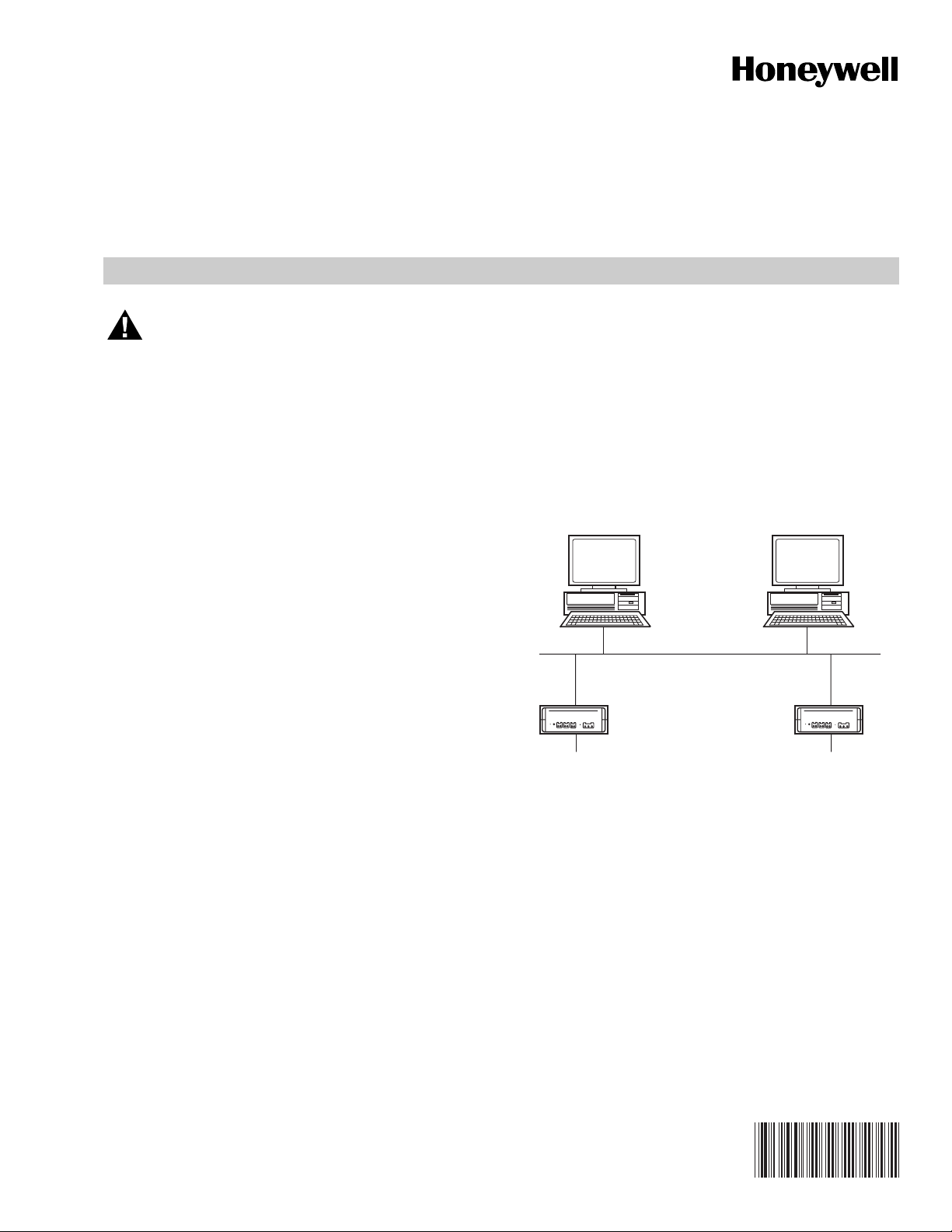
Additionally, each OVN is equipped with a RJ-45
10/100BaseT connector, plus an RS-232 interface.
(See Fig. 1).
INTERNET
BROWSER
INSTALLATION INSTRUCTIONS
EBI
EBI
WORKSTATION
The Q7055B1047 Open View Net Server (OVN) is a
Web-enabled operator interface that facilitates secure and
easy access to a Honeywell Building Management System
(BMS) through the Internet. It provides a connection of a
Honeywell XL5000 controller communication bus to an
industry standard TCP/IP Ethernet LAN/WAN, delivering
exceptional price/performance to meet the requirements of
both building owners and service providers.
With its combination of scalable performance, density and low
per-port pricing, the OVN allows network-layer capabilities to
be extended to a much wider range of network configurations
and environments. OVN supports a full range of Building
Management System (BMS) features such as commanding of
points as well as performing complex functions like alarm and
schedule management. Advanced features like graphics,
trends and reports give enhanced flexibility and total control
when accessing the Building Management System from a
remote location. Customers can now gain the advantages of
high-performance network and services, including traffic
management, to more locations throughout the network.
TCP/IP
OVN
SINGLE C-BUS
(ONLY FOR XL5000
CONTROLLERS
FAMILY)
Fig. 1. OVN network.
The Q7055B1047 OVN Server is used in systems for signaling
in energy management systems (UL 916). In addition, the
following standards apply: requirements of Canadian province
and local building codes; CEC 22.1 Canadian Code.
SINGLE C-BUS
(ONLY FOR XL5000
CONTROLLERS
FAMILY)
OVN
M25198
95-7711
Page 2
Q7055B1047 OPEN VIEW NET SERVER (OVN)
SPECIFICATIONS
Models: Q7055B1047 Open View Net Server (OVN).
Electrical Ratings:
Supply Voltage: 24 Vac, 50 to 60 Hz, 24 Vdc
(external power supply required).
Power Consumption: 8 VA.
Temperature Ratings:
Operating: 32° F to 120° F (0° C to 49° C).
Storage: -13° F to +185° F (-25° C to +85° C).
Humidity Ratings: 5 to 93% RH, non-condensing.
System Data:
Processor: AMD® SC2200, 266 MHz, 32 bit microprocessor.
Data Transfer: 10/100 Mbit/sec., 802.3 Ethernet.
LAN Interface: 10/100BaseT (RJ-45).
Field Bus: RS-485 DC coupled XL5000 C Bus.
Device Interface: Serial RS-232.
Memory: SODIMM, CompactFlash
OVN supports a maximum of 2,000 points
(access/subscription).
MTBF: 100,000 hours.
Safety:
Protection Standard: IP20 according to EN60529.
Protection Class: II according to EN60730-1.
Flame Retardant: V0 according to UL 94.
Dimensions (W x H x D): 2-13/16 in. (72 mm) x 8-13/16 in.
(224 mm) x 7-13/16 in. (199 mm).
®
.
• Building Network Adapter Installation Instructions.
• Bag of installation materials as follows: one
3-pole Phoenix power connector, two 2-pole Phoenix
controller bus channel connectors, four optional wall
mounting clips, four small inserts and four screws.
4. Read the CONNECTIONS section carefully prior to
connecting power and data interface cables to the OVN.
5. Refer to the INSTALLATION INSTRUCTIONS for each
component connected to the OVN:
• Form no. 95-7481, Excel 100, 500, 600 Series.
Controller Subpanel Installation Instructions.
• Form no. 95-7524, Excel 500/600 Control System
Installation Instructions.
• Form no. 95-7705, EBI™ LAN Interface Installation
Instructions.
WIRING
CAUTION
Shock Hazard.
Removal of the OVN cover can result in electrical
shock.
Do not remove cover. There are no user serviceable
parts inside.
Location and Mounting
The OVN server can be mounted in several ways; as a single
server or wall/cabinet mounted.
Weight: 3.0 lb (1.4 kg).
Approvals:
Electromagnetic Compatibility (EMC): EN50081-1 and
EN50082-2.
Electromagnetic Emission (EME): FCC Class A.
Energy Management: UL 916.
Additional Equipment:
DC Power Supply: 50017367-001, Jameco
®
Model No.
DDU240050, 120 Vac, 60 Hz input, 24 Vdc, 0.500 A
output, wall mounted power cube, Class 2.
DC Power Supply: Elpac Model No. FW7224-D5F, 120/240
Vac, 50/60 Hz input, 24 Vdc, 3.0 A output.
AC Power Supply: 120 Vac/50 to 60 Hz input, 24 Vac
output,14507287 series, or 14507350-002, listed.
Mounting: 14006090-555151 series communication panels.
50013930-001 Mounting Bracket
BEFORE INSTALLATION
Perform the following steps prior to installing the OVN server:
1. Verify that the product has been received without
damage.
2. Verify that the correct OVN server has been delivered.
3. Check the package contents. The following items are
included in each product package:
• Building Network Adapter device.
• Building Network Adapter driver software CD.
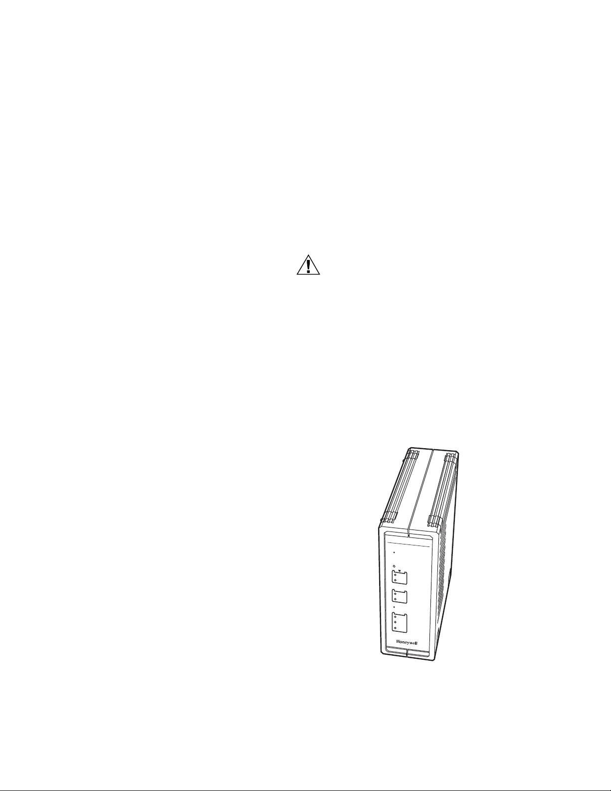
Single Server
Fig. 2 shows the single OVN server operating position; for
example, on a desk.
EXCEL
TM
5000
OPEN VIEW NET
R
eset
P
ow
er
Boot
N
M
L
C-B
US
R
x
Tx
Test
LAN
10
100
A
C
T
M25117
Fig. 2. Single server operating position.
95-7711 2
Page 3
Q7055B1047 OPEN VIEW NET SERVER (OVN)
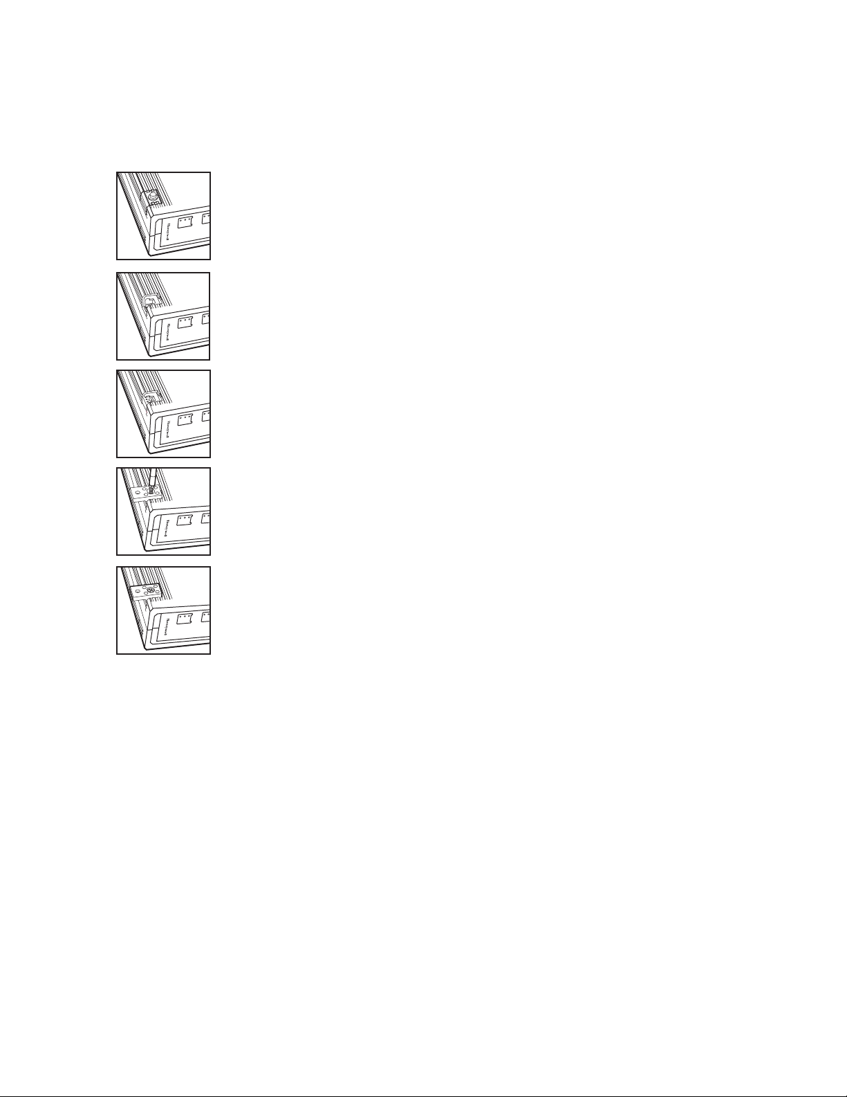
Wall Mounting
It is also possible to mount the OVN server to a wall. The
following sequence describes how the server should be
prepared prior to mounting it on a wall (see Fig. 3).
Place the OVN server with the topside
down on the desk.
R
Tx
x
LA
10
100
N
A
C
T
Remove the four feet from the bottom of
the OVN by pushing horizontally away from
the housing with a flat screwdriver.
R
Tx
x
LA
10
100
N
A
C
T
Push the four inserts (included) fully and
horizontally into the housing.
R
Tx
x
LA
10
100
N
A
C
T
Adjust the four retaining clips (included) on
top of the inserts. Fasten the retaining clips
with the included four screws.
R
T
L
x
A
x
1
1
A
N
0
0
C
0
T
Communications Panel Mounting
It is also possible to mount the OVN Server in the
14006090-555151 series EBI Communications Panel
(Refer to Fig. 4).
Use the housing with the clips to mark the
positions of the four mounting holes on the
wall surface. Drill 1/8 in. (4 mm) holes for
T
secure the OVN server.
the mounting screws (not included) and
R
T
L
x
A
x
1
1
A
N
0
0
C
0
Fig. 3. OVN wall mount.
M25121
3 95-7711
Page 4

Q7055B1047 OPEN VIEW NET SERVER (OVN)
TRIPP-LITE
WIRE PER NEC FOR FIRE ALARM
N
H
G
4
2 3
6
G
F
6
D
G
F
OVN
1
D
2
4 5
OVN
LIMITED AREA
TYPICAL MOUNTING LOCATIONS FOR 14005680-089582/592 FIBER OPTIC INTERFACE.
1
ALL WIRING MUST BE IN ACCORDANCE WITH NFPA 70, NATIONAL ELECTRICAL CODE AND
2
ALL APPLICABLE LOCAL CODES.
G = GROUNDING CONDUCTOR
3
GROUND CONNECTION. 8-32 STUD WITH 8-32 KEPS NUT.
4
GROUND CONNECTION FOR 14507678 SERIES PNET PROTECTOR AND OTHER
5
LOW VOLTAGE EQUIPMENT.
DRILLED MOUNTING HOLES FOR 14507719-001 8 PORT ETHERNET HUB (IF USED).
6
SYSTEM WIRING IS CLASSIFIED AS EITHER POWER LIMITED OR NON-POWER LIMITED
NOTE:
PER NEC ARTICLE 760. ALL POWER LIMITED WIRING MUST BE SEPARATED FROM ALL
NON-POWER LIMITED WIRING BY A MINIMUM DISTANCE OF 1/4 IN. (6 MM).
POWER LIMITED AREANON-POWER
M25120
Fig. 4. Typical mounting of Q7055B1047 OVN Assembly on 14006090-555151 series Communication Panel.
95-7711 4
Page 5

CONNECTIONS
Q7055B1047 OPEN VIEW NET SERVER (OVN)
This section describes how to connect power and the field bus
to the OVN server. A supply pack with installation material
containing the required connectors for power and the field bus
are shipped with the server.
Power Connection
The OVN server requires an external power supply with the
following specifications: 24 Vac, 50 Hz to 60 Hz, or 24 Vdc.
Typical power supplies include:
DC Power Supply: 50017367-001, Jameco Model No.
DDU240050, 120 Vac, 60 Hz input, 24 Vdc, 0.500 A
output, wall mounted power cube, Class 2.
DC Power Supply: Elpac Model No. FW7224-D5F, 120/240
Vac, 50/60 Hz input, 24 Vdc, 3.0 A output.
AC Power Supply: 120 Vac/50 to 60 Hz input, 24 Vac
output,14507287 series, 14507350-002, listed.
Power consumption of the OVN server is 8 VA.
For the power connection, the 3-pole Phoenix connector is
required (included).
Wire the power cable as follows:
1. Cut off the original connector at the end of the cable. In
case of a DIN connector equipped power cable, identify
the 24 Vdc cable pair using a multimeter. If the power
supply has screw terminals, wire a cable to the 24 V and
GND terminals on the power supply.
2. Strip the two power cable ends and insert each cable
end into the openings of the 3-pole Phoenix connectors
that are marked for power.
3. Fasten them with a screwdriver.
4. Connect a chassis ground to the third position on this
connector as marked.
NOTE: The polarity (+/-) of the 3-pole Phoenix power
connector for DC power supplies is don't care.
CABLES AND CONNECTORS
DB9F Null-Modem Connector
See Fig. 5 for serial connectors.
1 = DCD
2 = RxD
3 = TxD
4 = DTR
5 = GROUND
9 = RI
8 = CTS
7 = RTS
6 = DSR
M19592
Fig. 5. Serial connector (female connector is numbered as
shown).
Fig. 6 shows how to configure a DB9F Null-Modem Cable.
RxD
TxD
DTR
2
3
4
RxD
2
TxD
3
DSR
6
Field Bus Connection
The 2-pole Phoenix connector (included) is used to connect to
the field bus (see Fig. 12).
Consult form no. 74-4022, Q7055B1047 Open View Net
Server Checkout & Test for additional information on field bus
wiring.
DCD
1
DSR
6
GND
5
RTS
7
CTS
8
RI
99
DCD
1
DTR
4
GND
5
RTS
7
CTS
8
RI
M19594
Fig. 6. Signal connections for DB9F Null-Modem Cable.
5 95-7711
Page 6

Q7055B1047 OPEN VIEW NET SERVER (OVN)
Ethernet Connection
See Fig. 7 for OVN Ethernet connection.
8-PIN MODULAR
CONNECTOR RJ-45
M22399
Fig. 7. OVN Ethernet connector.
RJ-45 LAN Connector
The OVN provides a standard RJ-45 connector for
10/100BaseT Ethernet LAN connection. This section
describes the pin layout for the RJ-45 connector. Most
Ethernet local area networks use twisted pair wiring.
10/100BaseT networks are physically laid out in a star
topology, where each piece of equipment on the network is
connected to a central hub. The wiring is connected to
devices using a plug that resembles a phone jack called
RJ-45. See Table 1 for RJ-45 signals.
Connect OVN to HUB
To connect an OVN Server to a LAN via an Ethernet Hub, the
required cable should be configured as shown in Fig. 8.
Tx +
Tx -
Rx +
Rx -
1
2
3
4
5
6
7
8
Tx +
1
Tx -
2
Rx +
3
4
5
Rx -
6
7
8
M19596
Fig. 8. Straight-through pinning for OVN to Ethernet Hub
connections.
Connect OVN to Workstation
When an OVN needs a direct connection to a workstation
without using an Ethernet Hub, a crossover cable is required.
Fig. 9 shows how the different signals should be connected.
Table 1. RJ-45 Signals.
Pin Number Signal Name
1 Transmit (TX) +
2 Transmit (TX) -
3 Receive (RCV) +
4 Reserved
5 Reserved
6 Receive (RCV) -
7 Reserved
8 Reserved
Tx +
Tx -
Rx +
Rx -
1
2
3
6
4
5
7
8
Tx +
1
Tx -
2
Rx +
3
Rx -
6
4
5
7
8
M19597
Fig. 9. Crossover pinning for OVN to workstation, direct
connections.
COMMISSIONING
Finish the installation by commissioning the OVN in
accordance with form no. 74-4022, Q7055B1047 Open View
Net Server Checkout & Test.
95-7711 6
Page 7

OPERATION
Q7055B1047 OPEN VIEW NET SERVER (OVN)
For complete operating instructions, refer to form no. 74-4036,
Open View Net User’s Guide.
Location of Parts and Controls
Refer to Figures 10 and 11 and the following descriptions for
the location and function of parts and controls.
1—RESET
Hardware reset button. Located directly behind the small hole
in the front panel. To reach this button, a pointed object like a
sharp pen or an unfolded paper clip is necessary. Pressing
this button resets the Excel 5000 Open View Net Server
immediately.
2—POWER
Power indicator. This LED lights up when power is connected
to the Excel 5000 Open View Net Server.
3—HEARTBEAT LEDS
The BOOT and NML LEDs indicate the status of the Excel
5000 Open View Net Server. The BOOT LED blinks (Red)
during boot up. The NML LED lights (Green) during the
normal operation.
4—C-BUS
C-Bus activity display. This display contains two green LEDs;
one showing the Excel 5000 Open View Net Server receive
activity (Rx), and the other showing the Excel 5000 Open
View Net Server transmit activity (Tx).
TM
EXCEL
5000 OPEN VIEW NET
1
Reset
5—LAN
Local Area Network (LAN) activity display. Shows the actual
LAN traffic status using three LEDs:
— 10LNK. Ethernet speed of 10 mbps indicator (Green). If
this LED is lit, then the Ethernet link is operating at
10 mbps.
— 100LNK. Ethernet speed of 100 mbps indicator (Green). If
this LED is lit, then the Ethernet link is operating at
100 mbps.
— ACTIVITY. Link activity indicator (Green) will blink if there
is any activity (transmission/reception) on the LAN.
6—AC/DC IN 24 V
Power connector for 24 Vac (50 Hz to 60Hz) or 24 Vdc power
supplies and chassis ground. Power consumption is 8 VA
(connected via 10/100BaseT, cable). An external power
supply is required.
7—10/100BASET
10/100BaseT RJ-45 Ethernet LAN-connector, meets the
requirements of ANSI/TIA/EIA 586 Category 5, for unshielded
twisted pair connections.
8—RS-232
9-pin SUB-D male RS-232 connector, electrically isolated, PC
pin compatible, protected against spikes. This interface is
used for initial server setup and requires a standard
Null-Modem cable when interfacing to a PC.
9—C-BUS
2-pin connector for field bus channel 1 connection, electrically
isolated, meets EMC and FCC requirements.
10—C-BUS TERMINATION SWITCH
This switch is used to select field bus termination and biasing.
2
3
4
5
Power
Boot
NML
C-BUS
Rx
Tx
Tes t
LAN
10
100
ACT
M25118
Fig. 10. Excel 5000 Open View Net Server front panel.
7 95-7711
Page 8

Q7055B1047 OPEN VIEW NET SERVER (OVN)
The system must be maintained in accordance with the
system documentation and procedures and practices
contained in applicable standards. The Q7055B1047 OVN
Server has no user replaceable fuses.
For service, contact your local Honeywell Automation &
Control Solutions office as listed in the phone book, or contact
a regional office as shown at the end of this document.
10
9
8
7
6
M25267
C-BUS
AC/DC IN
NORMAL
B(-)
A(+)
10/100
24V
Fig. 11. Excel 5000 Open View Net Server rear panel.
Enterprise Buildings Integrator (EBI)™ and Excel 5000™ are trademarks of Honeywell International, Inc.
®
AMD
is a registered trademark of Advanced Micro Devices, Inc.
®
CompactFlash
is a registered trademark of Sandisk Corporation.
Jameco® is a registered trademark of Arndt Electronics Corporation
Automation and Control Solutions
Honeywell International Inc. Honeywell Limited-Honeywell Limitée
1985 Douglas Drive North 35 Dynamic Drive
Golden Valley, MN 55422 Toronto, Ontario M1V 4Z9
www.honeywell.com/buildingsolutions
® U.S. Registered Trademark
© 2006 Honeywell International Inc.
95-7711 J.I. 09-06
 Loading...