

Honeywell Q682B, Q682D, Q682L Application Manual
Q682B,D,L Switching Subbases
Application
Switching
Subbase Use with Thermostat System Fan Application LED Options
Q682B T8082A; T8085A,B,C;
T8090A, T8095, T8190
Q682D T8082A; T8085A,B,C;
T8090A, T8095, T8190
Q682L T8085R EM.HT.-HEAT-
HEAT-OFF-
COOL
ON-OFF or
AUTO-OFF
OFF-COOL
AUTO-ON Heating/Cooling Clogged Filter LED
AUTO-ON Heating-only or
None
Cooling-only
AUTO-ON Heat pump EM.HT. and AUX.
HT. LEDs
Installation
WHEN INSTALLING THIS PRODUCT
1. Read these instructions carefully. Failure to follow
them could damage the product or cause a hazardous
condition.
2. Check the ratings given in the instructions and on the
product to make sure the product is suitable for your
application.
3. Installer must be a trained, experienced service technician.
4. After installation is complete, check out product
operation as provided in these instructions.
CAUTION
1. Disconnect power supply to prevent electrical
shock or equipment damage.
2. On systems using a low-voltage gas valve,
never apply a jumper across valve coil terminals.
This may burn out thermostat heat anticipator.
IMPORTANT:
1. T8082, T8085, T8090, T8190 and T8095 Fuel Saver
Thermostats are mounted at true level when calibrated at the factory. An inaccurately leveled subbase will cause the temperature control to deviate
from set point.
2. Refer to thermostat Owner Manual for complete
installation instructions.
LOCATION
Locate the subbase about 5 ft. [1.5m] above the floor in
an area with good air circulation at average temperature.
Do not mount the subbase where the thermostat may be
affected by:
— drafts, or dead spots behind doors and in corners.
— hot or cold air from ducts.
— radiant heat from the sun, appliances or fireplace.
— concealed pipes and chimneys.
— unheated (uncooled) areas, such as an outside wall
behind the thermostat.
MOUNTING
1. If replacing an existing thermostat, remove thermostat and wallplate or subbase. To avoid miswiring, label
wires with the letter or number of each terminal as it is
disconnected. Be sure insulation on thermostat wires is in
good condition (not cracked, worn or frayed). Replace
wires if necessary.
If a new installation, prepare an opening for the thermostat wires, run wires and pull about 3 in. [76 mm] through
the opening.
NOTE: Color-coded, 18-gauge thermostat cable (Under-
writers Laboratories Inc., approved limited energy safety
control wire) with one conductor to each wiring terminal
is recommended.
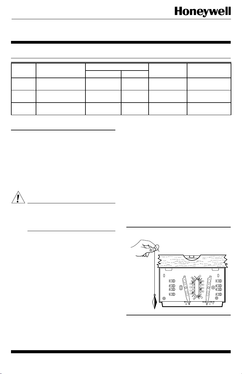
2. Use a spirit level for leveling the Q682 Switching
Subbase (Fig. 1) and mount to the wall with the three
screws provided. If mounting to a horizontal outlet box, use
the two machine screws furnished.
Fig. 1—Leveling the Q682 Switching Subbase.
SPIRIT LEVEL
PLUMB
LINE
PLUMB
BOB OR
WEIGHT
FAN
O
B
R
W
G
Y
AUTO OFF
HEATON
COOL
M1555
WIRING
Disconnect power supply before making wiring connec-
tions to prevent electrical shock or equipment damage.
All wiring must comply with local electrical codes and
ordinances.
J. H. • Rev. 4-94 • ©Honeywell Inc. 1994 • Form Number 60-1179—7
1 60-1179—7
A letter code is located near each terminal for easy
identification.
The shape of the terminal barrier permits insertion of
straight or conventional wraparound wiring connections.
Either method is acceptable. When making wiring connections, strip wire to length specified in Fig. 2.
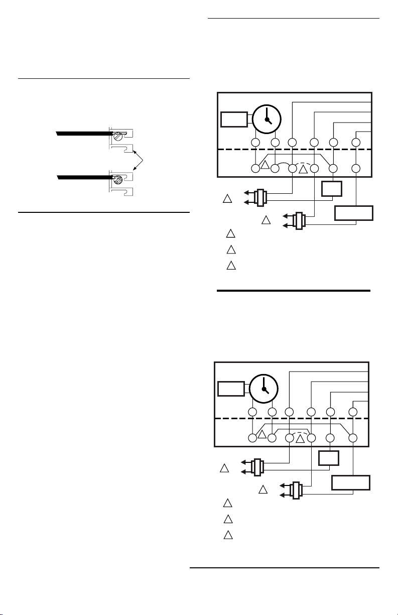
Fig. 3—Typical hookup for T8090A Thermostat clock powered through the control
system. Clock powered by battery when
heating or cooling equipment is on; clock
steals power from system when heating
equipment is off.
Fig. 2—Barrier configuration.
FOR STRAIGHT
CONNECTION—
STRIP 5/16 in. [8 mm]
FOR WRAPAROUND
CONNECTION—
STRIP 7/16 in. [11 mm]
BARRIER
M1556B
The Q682B or D Subbase allows the T8082A or
T8085A,B,C Thermostat clock to be powered by the system transformer or separate 24 Vac transformer. The Q682B
also allows the T8090A Thermostat clock to be powered by
the system transformer, separate 24 Vac transformer, batteries, or through the control system. Refer to Figs. 3 and 4
for hookup diagrams of a T8090A powered through the
control system.
The Q682L Subbase uses a separate clock transformer.
Ensure 24V exists between the R and X terminals. Wire the
X terminal to transformer common to operate the LEDs and
24V clock.
Follow the equipment manufacturer wiring instructions,
if available. If not available, refer to typical system hookups in Figs. 5 through 12.
Push any excess wire back into wall and plug the hole
carefully to prevent drafts from affecting the thermostat. To
mount and adjust thermostat, see the instructions included
with the thermostat.
THERMOSTAT
CLOCK
BATTERY
3
C C RH RC
SUBBASE
L1
(HOT)
1
L2
L1
(HOT)
1
1
POWER SUPPLY. PROVIDE DISCONNECT MEANS AND
OVERLOAD PROTECTION AS REQUIRED.
JUMPER RH-RC TERMINALS WHEN ONE TRANSFORMER
2
POWERS BOTH HEATING AND COOLING.
FOR POWER STEALING ON HEATING, JUMPER
3
C-RH AND C-W TERMINALS.
Fig. 4—Typical hookup for T8090A Thermostat clock powered through the control
system. Clock powered by battery when
heating or cooling equipment is on; clock
steals power from system when cooling
equipment is off.
THERMOSTAT
BATTERY
L2
CLOCK
2
WY
HEAT
RELAY
COMPRESSOR
CONTACTOR
M1514B
3
C C RH RC
SUBBASE
L1
(HOT)
1
L2
L1
(HOT)
1
1
POWER SUPPLY. PROVIDE DISCONNECT MEANS AND
OVERLOAD PROTECTION AS REQUIRED.
JUMPER R H-RC TERMINALS WHEN ONE TRANSFORMER
2
POWERS BOTH HEATING AND COOLING.
FOR POWER STEALING ON HEATING, JUMPER
3
C-RC AND C-Y TERMINALS.
L2
2
WY
HEAT
RELAY
COMPRESSOR
CONTACTOR
60-1179—72
M720

Fig. 5—Q682A Subbase with Fuel Saver Thermostat (T8195 shown) in an electric heat system with auto
fan.
COOL
ANTICIPATORS
BIMETAL
H
HEAT
ANTICIPATOR
W1
C
FALL
Y1
T8095A
THERMOSTAT
CLOCK
C1 C2
RED
BLUE
BIMETAL
HEAT
ANTICIPATOR
R1
C
H
FALL
OFF
COOL
O
COOLING
CHANGEOVER
HEAT
ANTICIPATOR
SYSTEM SWITCH
OFF
COOL
O
SYSTEM SWITCH
FAN
SWITCH
H
FAN
SWITCH
FALL
ON
G
FAN
ON
G
AUTO
AUTO
1
C
2
2
HEAT
ANTICIPATOR
OFF
HEAT
W
HEAT
COOL
Y
H
C
FALL
OFF
COOL
Y
3
HEATING COOLING
COOL
ANTICIPATORS
W
M7185
FILTER
LIGHT
2
SWITCH
Q682B
SUBBASE
HEAT
C
L1
(HOT)
1
L2
Fig. 6—Q682B Subbase with Fuel Saver Thermostat (T8195 shown) in a heating-cooling system with O
and B terminals for damper motors or changeover valve, and optional filter indicator LED.
CLOCK
T8095A
THERMOSTAT
Q682B
SUBBASE
C
R
B
R
HEATING
CHANGEOVER
POWER SUPPLY. PROVIDE DISCONNECT MEANS AND OVERLOAD PROTECTION AS REQUIRED.
1
JUMPER 1-2 FOR AUTO FAN IN HEAT AND COOL MODE; I.E. HEAT PUMP AND
2
ELECTRIC HEAT APPLICATIONS.
3
JUMPER 1-Y FOR AUTO FAN WITH COOLING MODE ONLY.
HEAT
B
L1
(HOT)
1
L2
HEAT
DAMPER
POWER SUPPLY. PROVIDE DISCONNECT MEANS AND OVERLOAD PROTECTION AS REQUIRED.
1
2
REMOTE INDICATION FOR FILTER (OPTIONAL).
COOL
DAMPER
FAN
RELAY
HEAT
RELAY
COMPRESSOR
CONTACTOR
M2496A
3 60-1179—7
 Loading...