

Y8196A (T8196A Thermostat/
Q682A Subbase) Heating/Cooling New
Construction Thermostat/Subbase
Package—Installation Instructions
Preparation
Check thermostat and subbase suitability for the heat-
ing, cooling, or heating/cooling system. Refer to Table 1.
Assemble tools required: flat bladed screwdriver, hand
or power drill with 3/16-in. drill bit, wire cutter/stripper or
sharp knife, bubble level or plumb bob and line.
TABLE 1—THERMOSTAT AND SYSTEM COMPATIBILITY.
Type of Heating System
to be Controlled Conditions/Compatibility
Electric (Line Voltage)—typical baseboard and
radiant
Gas—Direct Spark Ignition (DSI), Intermittent
Pilot (IP), and Standing Pilot (SP)
Heat Pump • Compatible. Assure correct subbase identity is selected for fan
Hot Water Zone • Honeywell 2-wire valves are compatible.
Oil • Compatible.
Vent Damper • Honeywell damper motors are compatible.
Warm Air Zone • Most are compatible.
a
If thermostat is not compatible with the system being controlled, the system will not operate. No hazard exists. The thermostat
will not be damaged unless it is used to directly control a line voltage system. A Honeywell R841 or R8239D1015 Isolating
Relay must be added to the thermostat control circuit for proper system operation.
b
Consult manufacturer for installation requirements.
• The R8239D1015 Isolating Relay or R841 Silent Switching
Center must be installed in the thermostat control circuit.
• Compatible.
control and changeover control (O terminal for cool and B
terminal for heat). Jumper Y to W for heat pump compressor
control.
• Some non-Honeywell 2-wire valves require an R8239D1015
Isolating Relay in the thermostat control circuit.
• Some 3-wire valves require an R8239A1052 Isolating Relay
in the thermostat control circuit.
• Some non-Honeywell damper motors require an R8239D1015
Isolating Relay in the thermostat control circuit.
control amperage requirement.
Assure power is off to the heating, cooling, or heating/
cooling system at the main fuse panel. Most buildings have
a separate switch box or circuit breaker for disconnecting
power to the heating and cooling (if applicable) equipment.
This thermostat is compatible with virtually all heating,
cooling or heating/cooling systems. Refer to Table 1 for
additional thermostat compatibility information.
a
a
a, b
a
Check
M3375
Recycling Notice
This control contains mercury in a sealed tube. Do not
place control in the trash at the end of its useful life.
If this control is replacing a control that contains mer-
cury in a sealed tube, do not place your old control in the
trash.
D. F. • Rev. 12-94 • ©Honeywell Inc. 1994 • • Form Number 69-0637—2
Contact your local waste management authority for
instructions regarding recycling and the proper disposal of
this control, or of an old control containing mercury in a
sealed tube.
1 69-0637—2
M3375
Installation
WHEN INSTALLING THIS PRODUCT…
1. Read these instructions carefully. Failure to follow
them could cause a hazardous condition.
2. Installer must be a trained experienced service techni-
cian.
3. After installation is complete, check out product op-
eration as provided in these instructions.
IMPORTANT: An incorrectly leveled subbase will cause
the temperature control to deviate from setpoint. It is
not a calibration problem.
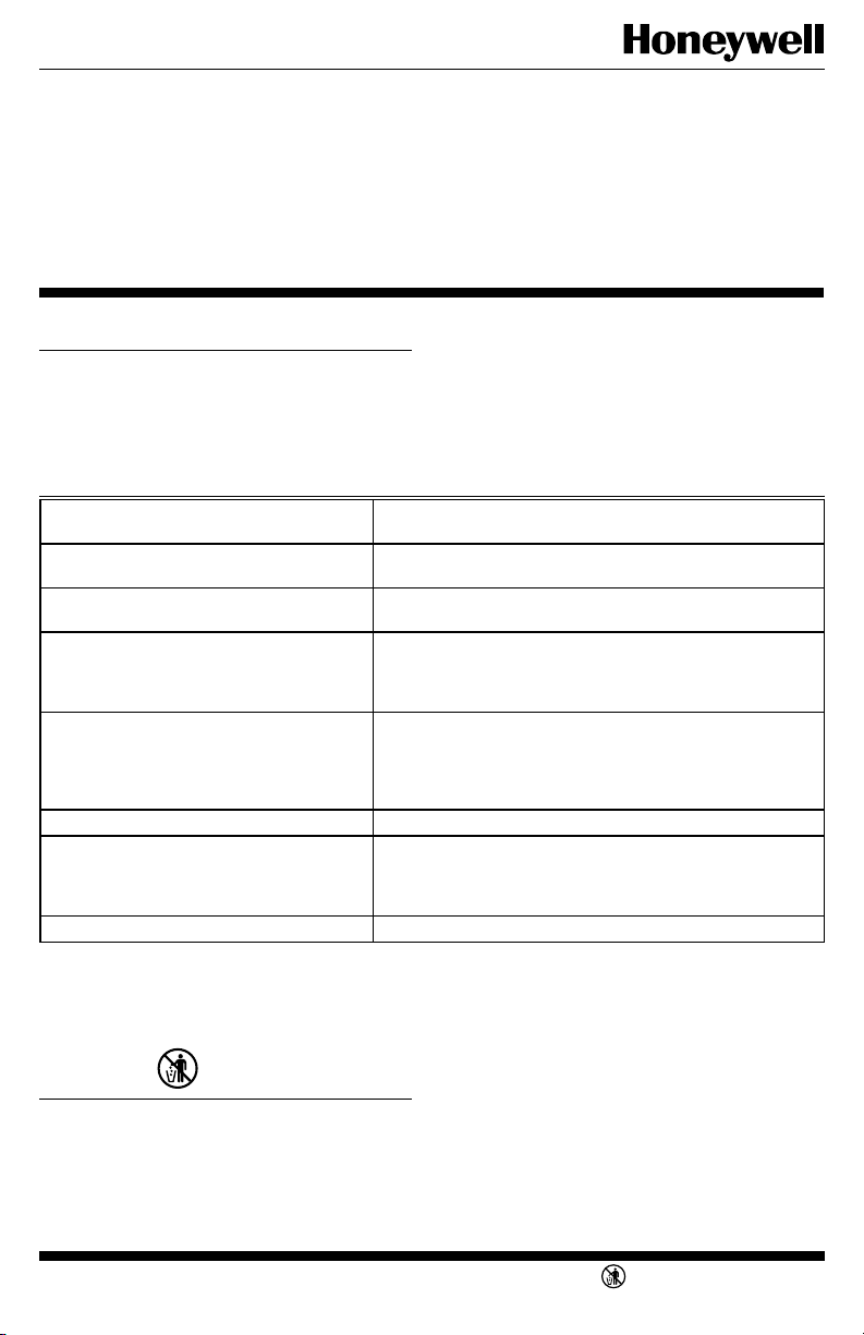
Fig. 1—Unpack thermostat.
CAPTIVE MOUNTING
SCREWS
1
12
2
3
11
4
1
0
5
9
6
8
7
7
8
6
9
10
11
12
LIFT
COVER
THERMOSTAT
COVER
35
0
3
25
20
10
CAUTION
1. Disconnect power supply to prevent electrical shock or equipment damage.
2. To prevent interference with the thermostat
linkage, keep wire length to a minimum and
run wires as close as possible to the subbase.
3. Do not overtighten thermostat captive mounting screws because damage to subbase
threads can result.
4. Do not short across coil terminals on relay.
This can burn out the thermostat heat anticipator.
LOCATION
Locate thermostat about 5 ft (1.5m) above the floor in an
area with good air circulation at average temperature. Do
not mount the thermostat where it may be affected by—
— drafts, or dead spots behind doors and in corners.
— hot or cold air from ducts.
— radiant heat from the sun or appliances.
— concealed pipes and chimneys.
— unheated (uncooled) areas such as an outside wall
behind the thermostat.
Run wires from the heating, cooling, or heating/cooling
equipment to the new thermostat location.
UNPACK THERMOSTAT
Handle your new thermostat carefully; rough handling
may interfere with its accuracy. Before unpacking, refer to
Fig. 1.
Remove and discard the shipping wrap.
IMPORTANT: Save package of screws and instructions
for the homeowner.
Remove the thermostat cover by lifting from the bottom.
Set aside cover until needed later.
Carefully remove the material protecting the mercury
switch bulb.
Loosen two captive mounting screws.
THERMOSTAT BASE
REMOVE
PACKING
MATERIAL
M8673
MOUNT SUBBASE
Wall Mounting (Fig. 2)
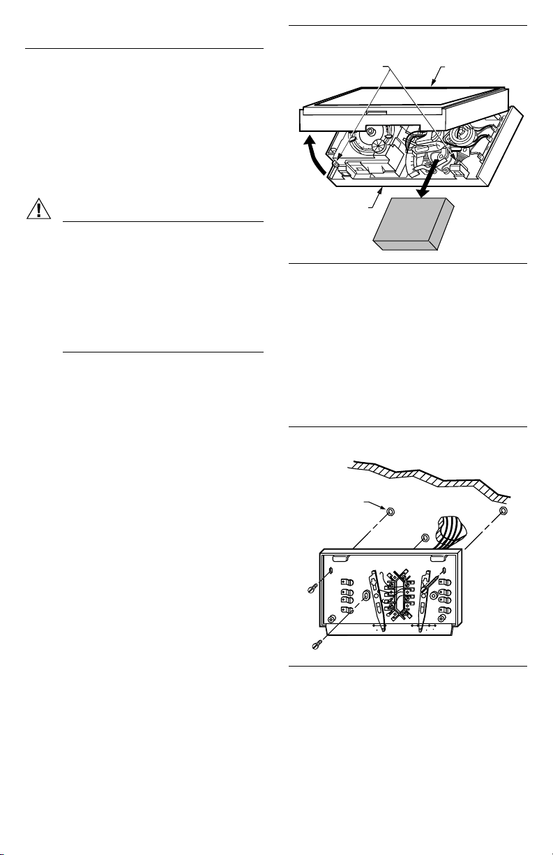
Hold the subbase in position on wall (Fig. 2).
Mark holes on the wall for anchors. Use spirit level to
make sure the wallplate or subbase is level.
Drill 3/16-in. holes, and gently tap anchors into holes
until flush with the wall.
Pull wires through the large wiring hole in the subbase.
Loosely fasten the subbase to the wall with the three
screws. Do not completely tighten the screws.
Carefully level the subbase (Fig. 3), and firmly tighten
the screws.
Fig. 2—Mounting subbase to wall.
3 SCREW HOLES
WITH PLASTIC
ANCHORS
O
B
R
W
G
FAN
HEATING/COOLING SUBBASE
Y
AUTO OFF
HEATON
COOL
M1552A
69-0637—2 2
 Loading...