

Page 1
T874R Thermostats and Q674L Subbases
Installation Instructions for the Trained Service Technician.
INSTALLATION INSTRUCTIONS
APPLICATION
The T874R Thermostat and Q674L Subbase provide 24 to 30 Vac control of 2-stage heating and 1-stage cool-ing heat
pump systems with manual changeover. Q674L Subbase provides EM.HT.-HEAT-OFF-COOL system switching and
AUTO-ON fan switching. See Table 1 for specific T874R/Q674L combinations.
Table 1. Thermostat/Subbase Specifications.
Thermostat/
b
b
Subbase
Model
Numbers
Q674L1207
Q674L1520
Q674L1587
Q674L1710
Q674L1736
Q674L1736
T874R1905/
Q674L1777
T874R1913/
Q674L1777
Q674L1827
Q674L1868
LED
Indication Changeover Comments
AUX.HT.,
EM. HT.
AUX.HT.,
EM. HT.
AUX.HT.,
EM. HT.,
CHECK
AUX.HT.,
EM. HT.,
CHECK
EM. HT. Manual Cool
EM. HT. Manual Cool
EM. HT. Manual Cool
EM. HT. Manual Cool
AUX.HT.,
EM. HT.
AUX.HT.,
EM.HT.
Manual Cool
Manual Heat
a
a
or Cool
Manual Heat
or Cool
Manual Heat
or Cool
Manual Cool Requires C815A Outdoor Thermister
Manual Heat
or Cool
TRADELINE®; adjustable stage 2
heat anticipation. Fixed anticipation
in stage 1. Auto fan in EM.HT.
TRADELINE®; fixed heat
anticipation. Auto fan in EM.HT.
SUPER TRADELINE®; fixed heat
anticipation. Factory installed jumper
across W1 and Y1. Auto fan in
EM.HT.
TRADELINE®; fixed heat
anticipation. Auto fan in EM.HT.
TRADELINE®; exact replacement
for York model no. 2TH11702224.
TRADELINE®; exact replacement
for York model nos. 2TH11702324
and 6TH11702224.
TRADELINE®; exact replacement
for York model nos. 2TH11702324
and 6TH11702224. Includes
C815A1054 Outdoor Thermistor.
TRADELINE®; exact replacement
for York model no. 2TH11702224.
for outdoor reset. Fixed stage 1 heat
anticipation. No heat anticipation in
stage 2 heat. Auto fan in EM.HT.
Replaces Y594R1136.
TRADELINE
®
See
Fig.
6
7
8
10
9
11
11
9
5
12
Thermostat/
Subbase
Package
Y594R1243 T874R1152/
Y594R1300 T874R1475/
Y594R1425 T874R1616/
Y594R1615 T874R1822/
Y594R1664 T874R1871/
Y594R1672 T874R1889/
Y594R1698
Y594R1706
Y594R1763 T874R1954/
Y594R1797 T874R1988/
a
EM.HT. LED also shows compressor malfunction.
b
Premier White® color.
®U.S. Registered Trademark
Copyright © 1997 Honeywell Inc. • • All Rights Reserved
X-XX UL
69-0392-9
Page 2
T874R THERMOSTATS AND Q674L SUBBASES
OPERATION
On a 2-heat thermostat, the two stages of heat
sequentially as the temperature drops.
mercury switch initiating a call for heat or cool.
There is about 1° F (0.6° C) between stages so the second stage makes only when the first stage can not handle
the load. The 1° F (0.6° C) is referred to as the
differential
The light emitting diodes (LED) on the subbase light when
something specific happens within the system. When an
LED lights, refer to this list for the meaning:
NOTE: LEDs are not field replaceable or addable.
.
EM. HT.: Emergency heat is operating. The compres-
sor has failed, and the heat pump is not operating.
LED lights when system switch is placed in the
EM.HT. position by the homeowner.
AUX.HT.: Auxiliary heat is operating, which means the
weather is so cold that the heat pump cannot handle
the load.
CHECK: System needs to be checked. See heating
sys-tem instructions for specific meaning.
RECYCLING NOTICE
This control contains mercury in a sealed tube. Do n
place control in the trash at the end of its useful life.
If this control is replacing a control that contains
mer-cury in a sealed tube, do
control in the trash.
Contact your local waste management authority for
instructions regarding recycling and the proper
disposal of this control, or of an old control
containing mercury in a sealed tube.
Make
refers to the
not
place your old
make
interstage
INSTALLATION
When Installing this Product…
1. Read these instructions carefully. Failure to follow
them could damage the product or cause a hazardous condition.
2. Check the ratings given in the instructions and on
the product to make sure the product is suitable for
your application.
3. Installer must be a trained, experienced service
technician.
4. After installation is complete, check out product
operation as provided in these instructions.
CAUTION
1. Disconnect power supply to prevent electrical
shock or equipment damage.
2. To prevent interference with the thermostat
linkage, keep wire length to a minimum and
run wires as close as possible to the subbase.
3. Push excess wire back into the hole and plug
hole to prevent drafts from affecting thermostat operation.
4. Do not overtighten thermostat captive
mounting screws because damage to
subbase threads can result.
5. Do not short across coil terminals on heating
relay or gas valve. This can burn out the
thermostat heat anticipator.
6. Never install more than one wire per terminal
unless factory-supplied jumper with spade
terminals is used.
IMPORTANT
Thermostats are calibrated at the factory using
subbase mounted at true level. Inaccurate
subbase leveling causes the actual temperature
to deviate from the setpoint temperature.
Location
Install the thermostat about 5 ft (1.5m) above the floor in
an area with good air circulation at average temperature.
Do not install the thermostat where it can be affected by:
ot
— drafts or dead spots behind doors and in corners.
— hot or cold air from ducts.
— radiant heat from sun or appliances.
— concealed pipes and chimneys.
— unheated (uncooled) areas such as an outside wall
behind the thermostat.
Mounting The Subbase
The thermostat subbase can be mounted on a vertical
outlet box, horizontal outlet box or directly on the wall.
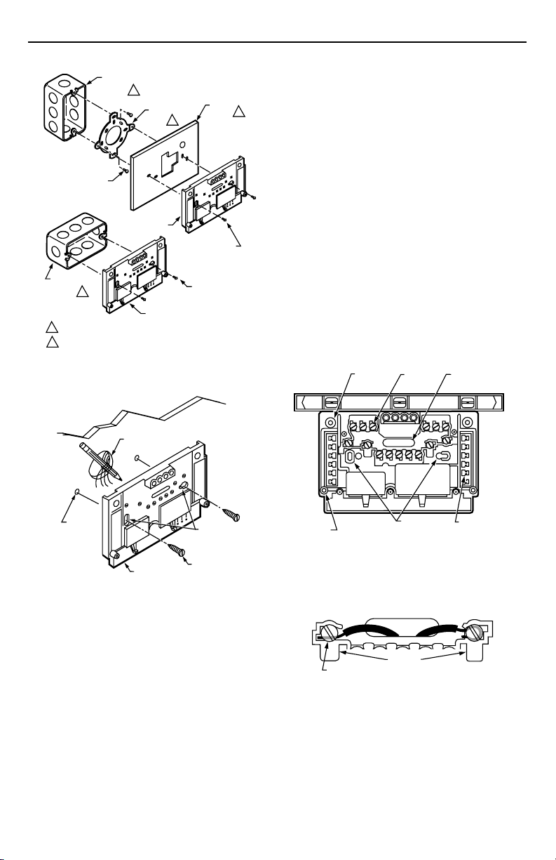
1. If you must mount the subbase on a vertical outlet
box, order Honeywell 193121A Adapter Assembly.
See Fig. 1. The assembly includes an adapter ring,
two screws and a cover plate to cover marks on the
wall. Install the ring and cover plate on the vertical
outlet box.
For a wall installation, hold subbase in position and
mark holes for anchors. See Fig. 2. Obtain wall
anchors locally. Be careful that the wires do not fall
back into the wall opening. Set aside subbase. Drill
two 3/16 in. (5 mm) holes and gently tap anchors
into the holes until flush with the wall.
69-0392—9
2
Page 3
T874R THERMOSTATS AND Q674L SUBBASES
VERTICAL
OUTLET
1
BOX
ADAPTER
RING
MOUNTING
SCREWS (2)
SUBBASE
HORIZONTAL
OUTLET
1
BOX
NOT INCLUDED WITH UNIT.
1
ACCESSORY PARTS AVAILABLE (193121A).
2
SUBBASE
2
COVER
PLATE
MOUNTING
SCREWS (2)
MOUNTING
SCREWS (2)
Fig. 1. Installation of subbase on outlet box.
WALL
WIRES THROUGH
WALL OPENING
2
M925
4. Secure the cover plate (if used) and subbase with
the screws provided. Do not fully tighten the
subbase screws.
5. Level the subbase by using a spirit level. Firmly
tighten subbase mounting screws. See Fig. 3. The
subbase mounting holes provide for minor out-oflevel adjustments.
IMPORTANT
An incorrectly leveled subbase causes the
temperature control to deviate from setpoint.
Wiring the Subbase
All wiring must comply with local electrical codes and
ordinances. Follow equipment manufacturer wiring
instructions when available. To wire subbase, proceed as
follows:
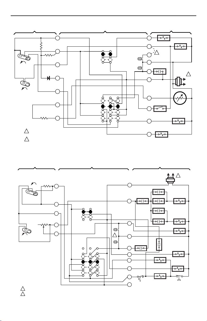
1. Connect the system wires to the subbase. See Fig.
5-12. A letter code for identification is located near
each terminal. The terminal barrier permits straight
or conventional wraparound wiring connection. See
Fig. 4.
2. Firmly tighten each terminal screw.
3. Fit wires as close as possible to the subbase. Push
excess wire back into the hole.
4. Plug the hole with nonflammable insulation to
prevent drafts from affecting the thermostat.
SPIRIT LEVEL
TOP
MOUNTING
HOLES (2)
WIRING
TERMINAL
THERMOSTAT
CABLE OPENING
WALL
ANCHORS
(2)
M926
SUBBASE
MOUNTING
HOLES
MOUNTING
SCREWS (2)
Fig. 2. Installation of subbase on wall.
2. Run wires to the thermostat location.
3. Pull wires through the cover plate (if used) and subbase cable opening. See Fig. 3.
IMPORTANT
Use 18 gauge, color-coded thermostat cable for
proper wiring.
MOUNTING
HOLES (2)
POST (2) FOR
MOUNTING
THERMOSTAT
TO SPRING FINGER
CONTACTS ON THE
THERMOSTAT
(UP TO 12)
Fig. 3. Subbase components and leveling procedure.
FOR STRAIGHT
INSERTION–
STRIP 5/16 IN. (8 MM)
SUBBASE TERMINAL SCREW
BARRIER
FOR WRAPAROUND–
STRIP 7/16 IN. (11 MM)
Fig. 4. Wiring connections.
3
M927
M928
69-0392—9
Page 4
T874R THERMOSTATS AND Q674L SUBBASES
THERMOSTAT
1
2
H1
C1
FALL
3
4
FALL
H2
5
6
11
POWER SUPPLY. PROVIDE DISCONNECT MEANS AND
1
OVERLOAD PROTECTION AS REQUIRED.
FIELD REMOVABLE JUMPER.
2
Fig. 5. Internal schematic and typical wiring diagram for Y594R1763 (T874R1954/Q674L1827). Replaces
H1
FALL
1
2
GE AY28X078, AY28X139; Trane Baystat 139, Baystat 239 and Baystat 240;
THERMOSTAT
H1/C1
ANTICIPATOR
FALL
C1
H2
ANTICIPATOR
H2
POWER SUPPLY. PROVIDE DISCONNECT MEANS AND OVERLOAD PROTECTION AS REQUIRED.
AUXILIARY HEAT LED AVAILABLE ON SOME MODELS.
and Honeywell Y594R1136 Thermostats.
2
3
4
5
6
FAN SWITCH
AUTO
ON
SYSTEM
SWITCH
EM. HT.
HEAT
OFF
COOL
SUBBASE SYSTEM COMPONENTS
G
W
AUTO
ON
FAN
SWITCH
AUX. HT.
LED (GREEN)
EM. HT.
LED (RED)
2
U
B
COMPRESSOR
MONITOR
F
R
SYSTEM
SWITCH
EM. HT.
HEAT
OFF
COOL
T
X2
OUTDOOR
THERMOSTAT
O
COMPRESSOR
RELAY
Y
SUBBASE
2
AUX. HT.
LED
(GREEN)
EM. HT.
LED (RED)
R
W3
W2
X
L
G
O
E
Y
B
SYSTEM COMPONENTS
RTD 1 EHR 1
SYSTEM
MONITOR
COOL CHANGEOVER
VALVE
LACO
ODT 1
ODT 2
EHR 2 RTD 3
RD
COMPRESSOR
CONTACTOR
FAN RELAY
(HOT) L1
AUX. HEATER
RELAY
OUTDOOR
THERMISTOR
COOL
CHANGEOVER
VALVE
M2970
L2
1
RTD 2
RTD 1
FAN RELAY
EM. HT.
RELAY
CHP
M5072A
Fig. 6. Internal schematic and typical wiring diagram for Y594R1243 (T874R1152/Q674L1207).
1
L1
(HOT)
L2
69-0392—9
4
Page 5

T874R THERMOSTATS AND Q674L SUBBASES
THERMOSTAT
H1
C1
FALL
H2
FALL
POWER SUPPLY. PROVIDE
1
DISCONNECT MEANS AND
OVERLOAD PROTECTION
AS REQUIRED.
2
CONNECT CHANGEOVER
RELAY TO B FOR HEAT
CHANGEOVER, TO O FOR
COOL CHANGEOVER.
H1/C1
ANTICIAPTOR
H2
ANTICIPATOR
2
3
4
5
6
8
10
FAN
SWITCH
AUTO
SYSTEM
SWITCH
EM. HT.
HEAT
OFF
COOL
SUBBASE
RTD 1
ON
EM. HT.
LED (RED)
AUX. HT.
LED
(GREEN)
R
L
X
W2
G
O
E
Y
B
LACO
SYSTEM COMPONENTS
ODT 1
RTD 2
EHR 1
ODT 2
RTD 3
EHR 2
COMPRESSOR
MONITOR
RD
2
COOL
CHANGEOVER VALVE
COMPRESSOR
CONTACTOR
L1
(HOT)
1
RTD 1
FAN RELAY
EM. HT. RELAY
CHP
HEAT
CHANGEOVER VALVE
L2
2
M1030A
Fig. 7. Internal schematic and typical wiring diagram for Y594R1300 (T874R1475/Q674L1520); fixed anticipation.
THERMOSTAT
H1
ANTICIPATOR
C ANTICIPATOR
H1
C
FALL
H2
ANTICIPATOR
H2
FALL
POWER SUPPLY. PROVIDE DISCONNECT MEANS AND OVERLOAD
1
PROTECTION AS REQUIRED.
2
REMOVE JUMPER WHEN W1 RELAY IS USED.
3
FACTORY-INSTALLED JUMPER.
Fig. 8. Internal schematic and typical wiring diagram for Y594R1425 (T874R1616/Q674L1587). SUPER
TRADELINE
1
2
3
4
5
6
11
®
; universal model for heat, cool, or first stage heating changeover systems.
CHECK LED has isolated terminals for use in all systems.
FAN
SWITCH
AUTO
ON
SYSTEM
SWITCH
EM. HT.
HEAT
OFF
COOL
SUBBASE
5
EM. HT.
LED (RED)
AUX. HT.
LED (GRN)
SYSTEM COMPONENTS
W3
O
L
G
R
W2
AUX. HT. RELAY
E
EM. HT. RELAY
X
3
HEAT
CHANGEOVER
X2
VALVE
B
W1 RELAY
W1
COMPRESSOR
2
RELAY
Y
W3 RELAY
COOL CHANGEOVER
VALVE
COMPRESSOR
MONITOR
FAN RELAY
M5067
L1
(HOT)
L2
1
69-0392—9
Page 6

T874R THERMOSTATS AND Q674L SUBBASES
SYSTEM COMPONENTS
FAN RELAY
G
R
AUX. HT. RELAY
W
H
"H" RELAY
B
X
EM. HT. RELAY
T
O
CHANGEOVER VALVE (COOL)
Y
COMPRESSOR
CONTACTOR
SYSTEM COMPONENTS
W3 RELAY
COOL
CHANGEOVER VALVE
COMPRESSOR
MONITOR
FAN RELAY
AUX. HT. RELAY
EM. HT. RELAY
HEAT
CHANGEOVER VALVE
COMPRESSOR
RELAY
L1
(HOT)
1
C815A1039
THERMISTOR
M3173A
1
M5068
L2
L1
(HOT)
L2
FAN SWITCH
AUTO
ON
SYSTEM
SWITCH
EM. HT.
HEAT
OFF
COOL
SUBBASE
SUBBASE
CHECK
LED (RED)
EM. HT.
LED
(RED)
AUX. HT.
LED
(GREEN)
EM. HT.
LED (RED)
W3
O
L
G
R
W2
E
X
B
Y
THERMOSTAT
2
FALL
H1
FALL
H2
POWER SUPPLY. PROVIDE DISCONNECT MEANS AND OVERLOAD PROTECTION AS REQUIRED.
1
Fig. 9. Internal schematic and typical wiring diagram for Y594R1664 (T874R1871/Q674L1736) and Y594R1706
THERMOSTAT
H1
FALL
H2
FALL
1
POWER SUPPLY. PROVIDE DISCONNECT MEANS AND
OVERLOAD PROTECTION AS REQUIRED.
Fig. 10. Internal schematic and typical wiring diagram for Y594R1615 (T874R1822/Q674L1710). TRADELINE;
H1/C1
ANTICIPATOR
C1
H2
ANTICIPATOR
RESET HEATER
3
4
5
6
11
12
(T874R1913/Q674L1777). Exact replacement for York model no. 2TH11702224.
H1
ANTICIPATOR
C
H2
ANTICIPATOR
C ANTICIPATOR
1
FAN
2
3
4
5
6
11
SWITCH
AUTO
ON
SYSTEM
SWITCH
EM .HT.
HEAT
OFF
COOL
intended for use in applications where W2 and E terminals are not jumpered.
69-0392—9
6
Page 7

T874R THERMOSTATS AND Q674L SUBBASES
SYSTEM COMPONENTS
FAN RELAY
G
R
AUX. HT. RELAY
W
H
"H" RELAY
B
X
EM. HT. RELAY
T
O
CHANGEOVER VALVE (COOL)
Y
COMPRESSOR
CONTACTOR
AUX. HT.
RELAY
AUX. HT.
RELAY
FAN RELAY
EM. HT. RELAY
COMPRESSOR
CONTACTOR
"B" RELAY
(HOT)
1
C815A1039
THERMISTOR
L1
(HOT)
L2
1
M3683A
L1
L2
M3173A
FAN SWITCH
AUTO
ON
SYSTEM
SWITCH
EM. HT.
SUBBASE
SYSTEM
SWITCH
EM. HT.
HEAT
OFF
COOL
HEAT
OFF
COOL
SUBBASE
EM. HT.
LED (RED)
SYSTEM COMPONENTS
R
L
EM. HT.
LED (RED)
3
W3
2
X
AUX. HT.
LED (GRN)
W2
G
COOL CHANGEOVER
VALVE
O
E
Y
B
THERMOSTAT
2
FALL
H1
FALL
H2
POWER SUPPLY. PROVIDE DISCONNECT MEANS AND OVERLOAD PROTECTION AS REQUIRED.
1
Fig. 11. Internal schematic and typical wiring diagram for Y594R1672 (T874R1889/Q674L1736) and Y594R1698
(T874R1905/Q674L1777). Exact replacement for York model nos. 2TH11702324 and 6TH11702224.
H1
1
2
3
H1/C1
ANTICIPATOR
C1
H2
ANTICIPATOR
RESET HEATER
THERMOSTAT
H1/C1
ANTICIPATOR
C1
FALL
H2
ANTICIPATOR
H2
FALL
POWER SUPPLY. PROVIDE DISCONNECT MEANS AND OVERLOAD PROTECTION AS REQUIRED.
TERMINAL LABELED C/X ON SOME MODELS.
W3 TERMINAL AVAILABLE ON SOME MODELS ONLY.
3
4
5
6
11
12
2
FAN
3
4
6
SWITCH
AUTO
ON
Fig. 12. Internal schematic and typical wiring diagram for Y594R1797 (T874R1988/Q674L1868).
7
69-0392—9
Page 8

T874R THERMOSTATS AND Q674L SUBBASES
Mounting the Thermostat
1. Remove the thermostat cover by pulling the bottom
edge of the cover away from the base until it snaps
free from the cover clip.
NOTE: The cover is hinged at the top and can be
removed by pulling out at the bottom.
2. Carefully remove and discard polystyrene packing
insert that protects the mercury switches during
shipment.
3. Turn over the thermostat base and note the spring
fingers that engage the subbase contacts. Make
sure the spring fingers are
proper electrical contact with the subbase.
4. Note the two tabs on the top inside edge of the
thermostat base. The tabs fit into corresponding
slots on the top of the subbase. Mount the thermostat on the subbase.
5. Align the two captive mounting screws in the
thermostat base with the posts on the subbase. See
Fig. 13. Tighten both screws.
screws
6. Hang the upper edge of the thermostat cover on top
or damage to subbase posts can result.
of the thermostat base and swing cover downward
until it engages with the cover clip.
THERMOSTAT
MOUNTING SLOTS (2)
SUBBASE
THERMOSTAT
M3266
not
bent flat, preventing
Do not overtighten
THERMOSTAT
MOUNTING POST (2)
0
8
0
7
0
6
0
5
T
A
E
H
CAPTIVE MOUNTING
SCREWS (2)
Fig. 13. Mounting thermostat on subbase.
SETTINGS
CAUTION
On systems using a gas valve, never apply a
jumper across the valve coil terminals, even
temporarily. This can burn out the thermostat heat
anticipator(s).
Heat Anticipator Setting
(2nd Stage Y594R1243)
Set the heat anticipator scale to match the primary control
current draw. When using a T874 Thermostat with two
stages of heating, set the heat anticipator to match the
respective primary control current draw. If the primary
control nameplate has no rating or if further adjustment is
necessary, use the following procedure to determine the
current draw. Measure the current draw with the thermostat removed and the power on.
1. Connect an ac ammeter of appropriate range
between the heating terminals of the subbase:
Stage 2: between W2 and R.
2. Move the system switch to HEAT.
3. After one minute, read the ammeter and record the
reading:
Stage 2: _______________amperes.
4. After mounting the thermostat, set the adjustable
heat anticipator to match the respective reading
measured in step 3.
If equipment cycles too fast, set the anticipator to a higher
current rating, not more than one-half division at a time,
and recheck cycle rate. Most conventional 2-stage heating
equipment is designed to operate at 3 cycles per hour per
stage. See Fig. 14.
Most heat pump systems should cycle 2-1/2 to 3 times
per hour.
.10
.12
.15
.2
.3
.4
1.2
.8
MOVE INDICATOR TO
MATCH CURRENT RATING
OF PRIMARY CONTROL
.6
M3684
Fig. 14. Adjustable heat anticipator scale.
Temperature Setting
Move the setpoint lever to the desired comfort position.
One lever controls both heating and cooling.
Subbase Setting
System switching positions control thermostat operation as
follows:
OFF: Heating and cooling systems are off. If the fan
switch is at the AUTO position, the cooling fan is
also off.
HEAT: Heating system is controlled by the thermostat.
Cooling system is off.
COOL: Cooling system is controlled by the thermostat.
Heating system is off.
EM.HT.: Emergency heat relay is energized on call for
heat. Cooling system is off. Compressor is deenergized.
Fan switching positions control fan operation as follows:
ON: Fan operates continuously.
AUTO: Fan operates as controlled by the thermostat.
To switch positions, use thumb and index finger to slide
lever to desired position. Stop switch lever in detent
directly over the desired function indicator mark for proper
circuit operation.
69-0392—9
8
Page 9

T874R THERMOSTATS AND Q674L SUBBASES
CHECKOUT
Heating
Move the system switch on the Q674 Subbase to HEAT.
Move the setpoint lever on the T874 Thermostat about
10° F (6° C) above room temperature. Both stages of
heating and the fan should start. Move the setpoint lever
about 10° F (6° C) below room temperature. Heating and
fan should shut off.
NOTE: To prevent compressor short cycling, some
manufacturer equipment includes a minimum-off
timer to provide a five-minute time delay before
turning on the compressor after the thermostat
last turned off the compressor, or after the
system first received power. This delay protects
the compressor.
Cooling
CAUTION
Do not operate cooling if the outdoor temperature
is below 50° F (10° C). Refer to manufacturer
recommendations.
Move the system switch on the Q674 Subbase to COOL.
Move the setpoint lever on the T874 Thermostat about
10° F (6° C) below room temperature. Cooling and fan
should start (see NOTE above). Move the setpoint lever
about 10° F (6° C) above room temperature. Cooling and
fan should stop.
Emergency Heat
Move the system switch to EM.HT. The EM.HT. LED
should come on. Move the setpoint lever about 10° F
(6° C) above room temperature. The electric strip heater(s)
should come on. Move the setpoint lever about 10° F
(6° C) below room temperature. The electric strip heater
should de-energize. The EM.HT. LED remains on until
system switch is moved to another position.
CALIBRATION
Thermostat
T874 Thermostats are accurately calibrated at the factory.
There is no provision for field calibration.
Thermometer
The thermometer in the thermostat has been accurately
calibrated at the factory. The thermometer should need
adjustment only if it was dropped or shifted due to
mishandling.
If the setpoint lever and the thermometer reading do not
agree:
1. Remove the thermostat cover by pulling out from the
bottom of cover until it clears the mounting slots.
2. Set the thermostat cover on a table near an
accurate thermometer.
3. Allow 10 or 15 minutes for cover thermometer to
sense area temperature; compare the readings. Be
careful not to touch thermometer or breathe on it.
4. If the readings are the same, replace cover and put
the system into operation.
5. If the readings are different, insert a small screwdriver into the thermometer and turn it until the
thermometers have the same reading. See Fig. 15.
6. Replace thermostat cover and put the system into
operation.
NOTE: Radiant heat from hands offsets the thermometer
reading. After making each adjustment, wait 10
or 15 minutes for the thermometer to stabilize
before comparing.
Fan
Move the subbase system switch to OFF and the fan
switch to ON. The fan should run continuously. When the
fan switch is in the AUTO position, fan operation is controlled by the heating or cooling system.
Fig. 15. Thermometer calibration
9
M5070
69-0392—9
Page 10

T874R THERMOSTATS AND Q674L SUBBASES
69-0392—9
10
Page 11

T874R THERMOSTATS AND Q674L SUBBASES
11
69-0392—9
Page 12

T874R THERMOSTATS AND Q674L SUBBASES
Automation and Control Solutions
Honeywell International Inc. Honeywell Limited—Honeywell Limitée
1985 Douglas Drive North 35 Dynamic Drive
Golden Valley, MN 55422 Scarborough, Ontario M1V 4Z9
69-0392—9
69-0392—9 G.H. Rev. 10-97 www.honeywell.com/yourhome
12
 Loading...