

Page 1
T874G,R Multistage Heat Pump Thermostats
and Q674F,J,L Subbases
INSTALLATION INSTRUCTIONS
APPLICATION
The T874G,R Thermostats with Q674F,J,L Subbases
provide 24 to 30 Vac control of a two-stage heating/one-
Table 1. Thermostat/Subbase Specifications.
Thermostat/Subbase System Fan Changeover
T874G/Q674F OFF-EM.HT.-HEAT-AUTO-COOL AUTO-ON Auto and Manual
T874G/Q674J EM.HT.-AUTO-OFF AUTO-ON Auto
T874R/Q674L EM.HT.-HEAT-OFF-COOL AUTO-ON Manual
stage cooling heat pump system. See Table 1 for
thermostat/subbase specifications.
Switching
OPERATION
On a two-heat thermostat, the two stages of heat
sequentially as the temperature drops.
mercury switch initiating a call for heat or cool.
There are about 2°F (1°C) between stages so that the
second stage makes only when the first stage cannot
handle the load. This is the
LEDs (light emitting diodes) are included on your subbase.
Refer to the list below for specific meaning.
The CHECK LED lights when something needs to be
checked or done to maintain efficient operation of the
system. See your heating system instructions for the
specific meaning.
The SYSTEM LED lights when the system is calling for
heating or cooling.
The AUX. HT. LED lights when the auxiliary heat (second
stage) is operating. Auxiliary heat operates when the heat
pump alone cannot handle the load.
The EM. HT. LED lights when the system switch is placed
in the EM. HT. position. Emergency heat is operating; in
most systems, the compressor has failed and the heat
pump is not operating.
LEDs are not field replaceable or addable.
interstage differential
Make
make
refers to the
.
RECYCLING NOTICE
This control contains mercury in a sealed tube. Do
not place the control in the trash at the end of its
useful life.
If this control is replacing a control that contains
mercury in a sealed tube, do
control in the trash.
Contact your local waste management authority for
instructions regarding recycling and the proper
disposal of this control, or of an old control
containing mercury in a sealed tube.
not
place your old
INSTALLATION
When Installing this Product…
1. Read these instructions carefully. Failure to follow
them could damage the product or cause a
hazardous condition.
2. Check the ratings given in the instructions and on
the product to make sure the product is suitable for
your application.
3. Installer must be a trained, experienced service
technician.
4. After installation is complete, check out product
operation as provided in these instructions.
Copyright © 1995 Honeywell Inc. • • All Rights Reserved
X-XX UL
69-0268-11
Page 2
T874G,R MULTISTAGE HEAT PUMP THERMOSTATS AND Q674F,J,L SUBBASES
쐃 If you must mount the subbase on a vertical outlet
CAUTION
1. Disconnect power supply to prevent electrical
shock or equipment damage.
2. Run wires as close as possible to the
subbase. To prevent interference with the
thermostat linkage, keep wire length to a
minimum. Push excess wire back into the hole
and plug the hole to prevent drafts from
affecting the thermostat operation.
3. Do not overtighten the thermostat captive
mounting screws because damage to the
subbase threads can result.
4. Do not short across coil terminals on relay;
this can burn out the heat anticipator.
Location
Install the thermostat about 5 ft (1.5m) above the floor in
an area with good circulation at room temperature.
Do not install the thermostat where it can be affected by:
— drafts, or dead spots behind doors and in corners.
— hot or cold air from ducts.
— radiant heat from sun or appliances.
— concealed pipes and chimneys.
— unheated (uncooled) areas such as an outside wall
behind the thermostat.
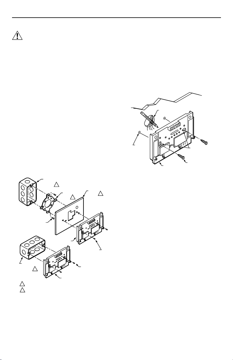
box, order part no. 193121A Adapter Assembly. See
Fig. 1. The assembly includes an adapter ring, two
screws, and a cover plate to cover marks on the
wall. Install the ring and cover plate on the vertical
outlet box.
For a wall installation, hold the subbase in position and
mark holes for the anchors. See Fig. 2. Obtain wall
anchors locally. Take care that the wires do not fall back
into the wall opening. Set aside the subbase. Drill four
3/16 in. (5 mm) holes and gently tap anchors into the
holes until flush with the wall.
WIRES THROUGH
WALL OPENING
WALL
ANCHORS
(2)
WALL
MOUNTING
HOLES
Mounting the Subbase
The thermostat subbase can be mounted on a vertical
outlet box, horizontal outlet box, or directly on the wall.
VERTICAL
OUTLET
1
BOX
ADAPTER
RING
MOUNTING
SCREWS (2)
SUBBASE
HORIZONTAL
OUTLET
1
BOX
NOT INCLUDED WITH UNIT.
1
ACCESSORY PARTS AVAILABLE (193121A).
2
SUBBASE
2
COVER
PLATE
MOUNTING
SCREWS (2)
MOUNTING
SCREWS (2)
Fig. 1. Installation of subbase on outlet box.
2
M925
M926
SUBBASE
MOUNTING
SCREWS (2)
Fig. 2. Installation of subbase on wall.
쐇 Pull wires through the cover plate (if used) and
subbase cable opening. See Fig. 12.
쐋 Secure the cover plate (if used) and subbase with
the screws provided. Do not fully tighten the
subbase screws.
쐏 Level the subbase using a spirit level, as shown in
Fig. 11, and firmly tighten the subbase mounting
screws. The subbase mounting holes provide for
minor out-of-level adjustments.
IMPORTANT
An incorrectly leveled subbase will cause the
temperature control to deviate from setpoint.
Wiring the Subbase
All wiring must comply with local electrical codes and
ordinances. Follow the equipment manufacturer wiring
instructions when available. To wire the subbase, proceed
as follows:
쐃 Connect system wires to the subbase. See Fig. 3
through 11. A letter code is located near each
terminal for identification. The terminal barrier
permits straight or conventional wraparound wiring
connection (Fig. 13).
쐇 Firmly tighten each terminal screw.
쐋 Fit wires as close as possible to the subbase. Push
excess wire back into the hole.
쐏 Plug the hole with nonflammable insulation to
prevent drafts from affecting the thermostat.
69-0268—11
2
Page 3
T874G,R MULTISTAGE HEAT PUMP THERMOSTATS AND Q674F,J,L SUBBASES
THERMOSTAT SUBBASE SYSTEM COMPONENTS
CO
FALL
H1
RISE
H1 ANTICIPATOR
H2
ANTICIPATOR
FALL
H2
C1
C1 ANTICIPATOR
RISE
1
2
4
6
8
9
10
11
12
FAN SWITCH
AUTO
ON
SYSTEM
SWITCH
OFF
EM. HT.
HEAT
AUTO
COOL
POWER SUPPLY. PROVIDE DISCONNECT MEANS AND
1
OVERLOAD PROTECTION AS REQUIRED.
TERMINAL LABELED C/X ON SOME MODELS.
2
W3 TERMINAL ON SOME MODELS ONLY.
3
O
COOL CHANGEOVER
VALVE
G
B
3
W3
R
E
L
EM. HT.
LED (RED)
2
X
AUX. HT.
LED (GREEN)
W2
Y
B RELAY
AUX HT. RELAY
EM. HT. RELAY
AUX. HT. RELAY
FAN RELAY
COMPRESSOR
CONTACTOR
M5986A
L1
(HOT)
L2
1
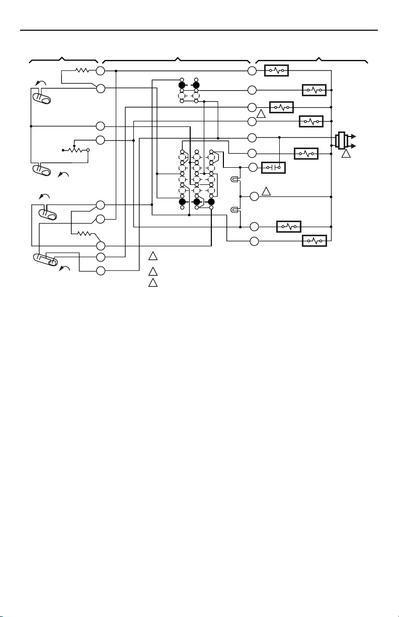
Fig. 3. Internal schematic and typical hookup for T874G/Q674F in heat pump system. Includes AUX. HT. and EM.
HT. LEDs.
3
69-0268—11
Page 4
T874G,R MULTISTAGE HEAT PUMP THERMOSTATS AND Q674F,J,L SUBBASES
THERMOSTAT
1
H1
H1
ANTICIPATOR
FALL
2
4
FALL
H2
H2 ANTICIPATOR
RISE
CO
C1
ANTICIPATOR
RISE
C1
POWER SUPPLY. PROVIDE DISCONNECT MEANS AND OVERLOAD PROTECTION AS REQUIRED.
1
REMOVE JUMPER FOR INDEPENDENT CONTROL OF W1 AND E TERMINALS.
2
6
8
9
10
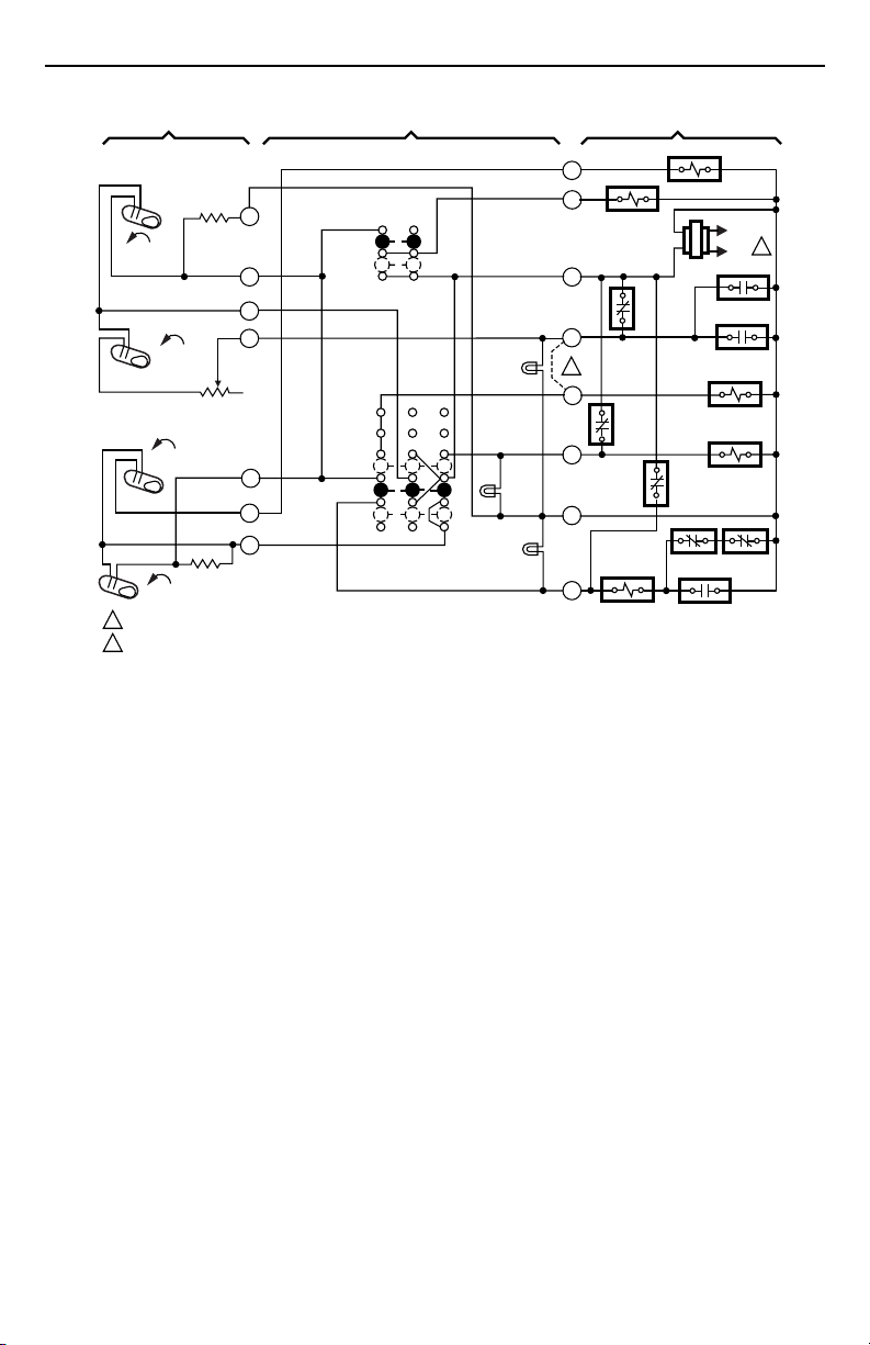
Fig. 4. Internal schematic and typical hookup for T874G/Q674J in heat pump system. Includes AUX. HT., CHECK
SUBBASE
FAN
SWITCH
AUTO
ON
SYSTEM
SWITCH
EM. HT.
AUTO
OFF
and SYSTEM LEDs.
AUX. HT.
LED
(YELLOW)
SYSTEM
LED
(GREEN)
CHECK
LED
(RED)
O
G
R
W1
2
E
X
C
Y
FAN RELAY
COMPRESSOR
CONTACTOR
SYSTEM COMPONENTS
COOL CHANGEOVER
VALVE
3R
4R
5R
HPS
4R
L2
L1
(HOT)
SEQ 2
SEQ 1
EM. HT.
RELAY
4R
1
4R
M1629
69-0268—11
4
Page 5

T874G,R MULTISTAGE HEAT PUMP THERMOSTATS AND Q674F,J,L SUBBASES
THERMOSTAT
2
H1
C1
FALL
H1/C1
ANTICIPATOR
H2
FALL
1
POWER SUPPLY. PROVIDE DISCONNECT
MEANS AND OVERLOAD PROTECTION
AS REQUIRED.
FACTORY-INSTALLED JUMPER.
2
H2 ANTICIPATOR
RESET
Fig. 5. Internal schematic and typical hookup for T874R/Q674L in heat pump system with outdoor reset. Includes
3
4
5
6
11
12
AUX. HT., CHECK and SYSTEM LEDs.
FAN
SWITCH
AUTO
ON
SYSTEM
SWITCH
EM. HT.
HEAT
OFF
COOL
SUBBASE
AUX. HT.
LED
(YELLOW)
CHECK
LED
(RED)
SYSTEM
LED (GREEN)
O
COOL
CHANGEOVER VALVE
G
R
W1
2
EM. HT. RELAY
E
X
C
C815A OUTDOOR
THERMISTOR
T
Y
SYSTEM COMPONENTS
FAN RELAY
L1
(HOT)
L2
1
COMPRESSOR
FAILURE
COMPRESSOR
CONTACTOR
M1628A
5
69-0268—11
Page 6

T874G,R MULTISTAGE HEAT PUMP THERMOSTATS AND Q674F,J,L SUBBASES
THERMOSTAT
2
FALL
H1
C1
H1/C1
ANTICIPATOR
H2
FALL
1
2
H2
ANTICIPATOR
POWER SUPPLY. PROVIDE DISCONNECT MEANS AND OVERLOAD PROTECTION AS REQUIRED.
REMOVE JUMPER FOR INDEPENDENT CONTROL OF W1 AND E TERMINALS.
RESET
3
4
SYSTEM
5
6
11
12
SWITCH
Fig. 6. Internal schematic and typical hookup for T874R/Q674L in heat pump system with outdoor reset. Includes
SUBBASE
AUX. HT.
LED
(YELLOW)
O
G
R
W1
E
X
C
C815A
OUTDOOR
THERMISTOR
T
Y
FAN
SWITCH
AUTO
ON
EM. HT.
HEAT
OFF
COOL
EM. HT.
LED
(RED)
SYSTEM
LED
(GREEN)
AUX. HT., EM. HT. and SYSTEM LEDs.
COOL CHANGEOVER
VALVE
3R
2
4R
SYSTEM COMPONENTS
FAN RELAY
SEQ 2
EM. HT. RELAY
5R
HPS
COMPRESSOR
CONTACTOR
L1
(HOT)
L2
SEQ 1
4R
1
4R
4R
M1858
L1
L2
H1
1 POWER SUPPLY. PROVIDE
M6565
H1/C1
C1
ANTICIPATOR
FALL
H2
ANTICIPATOR
H2
FALL
DISCONNECT MEANS AND
OVERLOAD PROTECTION
AS REQUIRED.
Fig. 7. Internal schematic and typical hookup for T874R/Q674L in heat pump system. Includes EM. HT and AUX.
69-0268—11
2
3
AUTO
4
ON
6
EM. HT.
HEAT
OFF
COOL
EMERGENCY
HEAT
(RED)
AUXILIARY
HEAT
(GREEN)
R
L
X
W2
G
O
E
Y
B
26.5 VAC
TRANSFORMER
AUXILIARY
HEAT RELAY
CHANGEOVER
RELAY
COMPRESSOR
RELAY
HT. LEDs.
6
(HOT)
EM. HT. RELAY
FAN RELAY
EM. HT. RELAY
B RELAY
1
Page 7

T874G,R MULTISTAGE HEAT PUMP THERMOSTATS AND Q674F,J,L SUBBASES
THERMOSTAT
H1
ANTICIPATOR
C ANTICIPATOR
H1
C
FALL
H2
ANTICIPATOR
H2
FALL
POWER SUPPLY. PROVIDE DISCONNECT MEANS AND OVERLOAD
1
PROTECTION AS REQUIRED.
2
REMOVE JUMPER WHEN W1 RELAY IS USED.
3
FACTORY-INSTALLED JUMPER.
1
2
3
4
5
6
11
Fig. 8. Internal schematic and typical hookup for T874R/Q674L in heat pump system. Includes CHECK, EM. HT.
SUBBASE
FAN
SWITCH
AUTO
ON
SYSTEM
SWITCH
EM. HT.
HEAT
OFF
COOL
and AUX. HT. LEDs.
EM. HT.
LED (RED)
AUX. HT.
LED (GRN)
SYSTEM COMPONENTS
W3
O
L
G
R
W2
AUX. HT. RELAY
E
EM. HT. RELAY
X
3
HEAT
CHANGEOVER
X2
VALVE
B
W1 RELAY
W1
COMPRESSOR
2
RELAY
Y
W3 RELAY
COOL CHANGEOVER
VALVE
COMPRESSOR
MONITOR
FAN RELAY
M5067
L1
(HOT)
L2
1
7
69-0268—11
Page 8

T874G,R MULTISTAGE HEAT PUMP THERMOSTATS AND Q674F,J,L SUBBASES
THERMOSTAT
H1/C1
ANTICIPATOR
FALL
H1
C1
H2
ANTICIPATOR
H2
FALL
1
POWER SUPPLY. PROVIDE DISCONNECT MEANS AND OVERLOAD PROTECTION AS REQUIRED.
2
AUXILIARY HEAT LED AVAILABLE ON SOME MODELS.
Fig. 9. Internal schematic and typical hookup for T874R/Q674L in heat pump system. Includes EM. HT. and AUX.
2
3
4
5
6
EM. HT.
HT. LEDs and W3 terminal for additional heat stage.
FAN SWITCH
AUTO
ON
SYSTEM
SWITCH
HEAT
OFF
COOL
SUBBASE
2
AUX. HT.
LED
(GREEN)
EM. HT.
LED (RED)
R
W3
W2
X
L
G
O
E
Y
B
SYSTEM COMPONENTS
RTD 1 EHR 1
SYSTEM
MONITOR
COOL CHANGEOVER
VALVE
LACO
(HOT) L1
ODT 1
ODT 2
EHR 2 RTD 3
RD
COMPRESSOR
CONTACTOR
L2
1
RTD 2
RTD 1
FAN RELAY
EM. HT.
RELAY
CHP
M5072A
69-0268—11
8
Page 9

T874G,R MULTISTAGE HEAT PUMP THERMOSTATS AND Q674F,J,L SUBBASES
THERMOSTAT
2
H1/C1
ANTICIPATOR
C1
H2
ANTICIPATOR
3
4
6
H1
FALL
H2
FALL
POWER SUPPLY. PROVIDE DISCONNECT MEANS AND OVERLOAD PROTECTION AS REQUIRED.
1
2
TERMINAL LABELED C/X ON SOME MODELS.
3
W3 TERMINAL AVAILABLE ON SOME MODELS ONLY.
Fig. 10. Internal schematic and typical wiring diagram for T874R/Q674L in heat pump system. Includes EM. HT.
SUBBASE
FAN
SWITCH
AUTO
ON
SYSTEM
SWITCH
EM. HT.
HEAT
OFF
COOL
and AUX. HT. LEDs.
SYSTEM COMPONENTS
R
L
EM. HT.
LED (RED)
3
W3
2
X
AUX. HT.
LED (GRN)
W2
G
COOL CHANGEOVER
VALVE
O
E
EM. HT. RELAY
Y
COMPRESSOR
CONTACTOR
B
AUX. HT.
RELAY
AUX. HT.
RELAY
FAN RELAY
"B" RELAY
M3683A
L1
(HOT)
L2
1
Mounting the Thermostat
쐃 Remove the thermostat cover by pulling the bottom
edge of the cover outward and away from the base
until it snaps free of the retaining posts.
NOTE: The cover is hinged at the top and must be
removed by pulling the bottom edge
outward and away from the base.
쐇 Carefully remove and discard the polystyrene
packing insert that protects the mercury switches
during shipment.
쐋 Turn over the thermostat base and note the spring
fingers that engage the subbase contacts. Make
sure the spring fingers are
proper electrical contact with the subbase.
쐏 Note the tabs along the top inside edge of the
thermostat base. The tabs fit into the corresponding
slots on the top of the subbase. Mount the
thermostat on the subbase.
쐄 Align the two captive mounting screws in the
thermostat base with the posts on the subbase. See
Fig. 14. Tighten both screws.
screws
or damage to subbase can result.
not
bent flat, preventing
Do not overtighten
9
69-0268—11
Page 10

T874G,R MULTISTAGE HEAT PUMP THERMOSTATS AND Q674F,J,L SUBBASES
1
L1
(HOT)
L2
CHECK
LED
(RED)
SYSTEM
LED
(GREEN)
O
G
R
W
2
E
X
C
T
Y
COMPRESSOR
CONTACTOR
CHANGEOVER
RELAY
FAN RELAY
3R
4R
5R
SEQ 2
SEQ 1
EM. HT. RELAY
4R
HPS 4R
4R
M1627A
FALL
H1
C1
H1/C1
ANTICIPATOR
FALL
H2
H2
ANTICIPATOR
1 POWER SUPPLY. PROVIDE DISCONNECT MEANS AND OVERLOAD PROTECTION AS REQUIRED.
REMOVE JUMPER FOR INDEPENDENT CONTROL OF W AND E TERMINALS.
2
Fig. 11. Internal schematic and typical hookup for T874R/Q674L in heat pump system. Includes AUX. HT., CHECK
FAN
SWITCH
AUTO
ON
SYSTEM
SWITCH
EM. HT.
HEAT
OFF
COOL
and SYSTEM LEDs.
AUXILIARY
HEAT
LED
(YELLOW)
SPIRIT LEVEL
MOUNTING
HOLES (2)
TOP
MOUNTING
HOLES (2)
WIRING
TERMINAL
POST (2) FOR
MOUNTING
THERMOSTAT
THERMOSTAT
CABLE OPENING
TO SPRING FINGER
CONTACTS ON THE
THERMOSTAT
(UP TO 12)
M927
Fig. 12. Subbase components and leveling procedure.
69-0268—11
10
FOR STRAIGHT
INSERTION–
STRIP 5/16 in. (8 mm)
SUBBASE TERMINAL SCREW
Fig. 13. Wiring connections.
BARRIER
FOR WRAPAROUND–
STRIP 7/16 in. (11 mm)
M928
Page 11

T874G,R MULTISTAGE HEAT PUMP THERMOSTATS AND Q674F,J,L SUBBASES
THERMOSTAT
MOUNTING SLOTS (2)
THERMOSTAT
MOUNTING POST (2)
50 60 70 80
SUBBASE
THERMOSTAT
M3266
Fig. 14. Mounting thermostat on subbase.
HEAT
CAPTIVE MOUNTING
SCREWS (2)
SETTING
Temperature Setting
The T874R has one setpoint lever that controls both
heating and cooling. The T874G has one lever that
controls heating and another lever that controls cooling.
Move the setpoint lever(s) to the desired control
position(s).
Subbase Setting
System switching positions control thermostat operation as
follows:
EM. HT.: Emergency heating system is energized. Cooling
system is off. Compressor is de-energized.
HEAT: Heating system is controlled by the thermostat.
Cooling system is off.
OFF: Both the heating and cooling systems are off.
COOL: Cooling system is controlled by the thermostat.
Heating system is off.
AUTO: Thermostat automatically changes between heat
and cool modes depending on indoor temperature.
Fan switching positions control fan operation as follows:
ON: Fan operates continuously.
AUTO: Fan operates with equipment as controlled by the
thermostat.
To switch positions, use your thumb and index finger to
slide the lever to the desired position. The switch lever
must be set directly over the desired function indicator
mark for proper circuit operation.
Cooling
CAUTION
Do not operate cooling if outdoor temperature is
below 50°F (10°C). Refer to manufacturer
recommendations.
Move the system switch on the subbase to COOL. Move
the setpoint lever (cooling lever on T874G) on the thermostat about 10°F (6°C) below the room temperature.
Cooling and fan should start. Move the lever (cooling lever
on T874G) about 10°F (6°C) above the room temperature.
Cooling and fan should stop.
Emergency Heat
Move the system switch on the subbase to EM. HT. Move
the setpoint lever (heating lever on T874G) about 10°F
(6°C) above the room temperature. The electric strip
heater(s) should come on. Move the lever (heating lever
on T874G) about 10°F (6°C) below the room temperature.
The electric strip heater should de-energize.
Fan
Move the subbase system switch to OFF, and the fan
switch to ON. The fan should run continuously. When the
fan switch is in the AUTO position, fan operation is
controlled by the heating or cooling system.
Outdoor Reset Thermistor
Some systems are supplied with a Honeywell C815A1005
Thermistor for outdoor mounting. The thermistor must be
used; if not, thermostat performance will deviate radically
from proper operation.
The proper thermistor operation must be verified to assure
the correct operation of the thermostat. Check thermistor
operation as follows:
쐃 Disconnect the T wire on the subbase.
쐇 Use an ohmmeter to measure resistance between
the T wire and the transformer secondary common
or C terminal.
쐋 Take outdoor temperature at thermistor location
and find the correct thermistor resistance on chart
in Fig. 15.
쐏 If the resistance measured in step 2 and the
calculated resistance in step 3 vary by more than
15 percent, the thermistor requires replacement.
Contact the installation dealer for an outdoor
thermistor replacement.
CHECKOUT
Heating
Move the system switch on the subbase to HEAT and the
fan switch to AUTO. Move the setpoint lever (heating lever
on T874G) on the thermostat about 10°F (6°C) above the
room temperature. Heating and fan should start if there is
no time delay or outdoor temperature limiting system.
Move the lever (heating lever on T874G) about 10°F (6°C)
below the room temperature. Heating and fan should shut
off.
CALIBRATION
Thermostat
These thermostats are accurately calibrated at the factory.
They do not have provision for field calibration.
Thermometer
The thermometer in your thermostat has been accurately
calibrated at the factory. The thermometer should only
need adjustment if it has been dropped or jarred.
11
69-0268—11
Page 12

T874G,R MULTISTAGE HEAT PUMP THERMOSTATS AND Q674F,J,L SUBBASES
If the setpoint lever setting and the thermometer reading
do not agree, follow the procedure below.
쐃 Remove thermostat cover by pulling the bottom
edge of the cover outward and away from the base
until it clears the retaining posts.
쐇 Set the cover on a table near an accurate
thermometer.
쐋 After allowing five or ten minutes for stabilization,
compare the readings. If they are the same, replace
cover and put system into operation. If they are
different, recalibrate the thermostat thermometer;
see step 4.
4600
4400
4200
4000
3800
3600
3400
3200
3000
2800
2600
2400
2200
2000
1800
1600
1400
THERMISTOR RESISTANCE (ohms)
1200
1000
800
600
400
200
0
-20 0 20 40 60 80 100 120 140
C815A THERMISTOR RESISTANCE
R = 400 ohms ± 10% AT 77°F (25°C)
TEMPERATURE OF THERMISTOR (°F)
M1590A
Fig. 15. Thermistor resistance chart.
쐏 Insert a small screwdriver in the thermometer shaft
(Fig. 16) and turn it until the thermometers read the
same. When the thermometer is calibrated, replace
cover and place into operation.
NOTE: Radiant heat from your hands will offset the
thermometer reading. After making each
adjustment, wait five or ten minutes for the
thermometer to stabilize before comparing.
M5070
Fig. 16. Thermometer calibration.
Home and Building Control
Honeywell Inc.
1985 Douglas Drive North
Golden Valley, MN 55422
69-0268—11
69-0268—11 J.S. Rev. 12-95
Home and Building Control
Honeywell Limited-Honeywell Limitée
35 Dynamic Drive
Scarborough, Ontario M1V 4Z9
12
www.honeywell.com/yourhome
 Loading...