

Page 1
Put UPC Code Here
P7810C
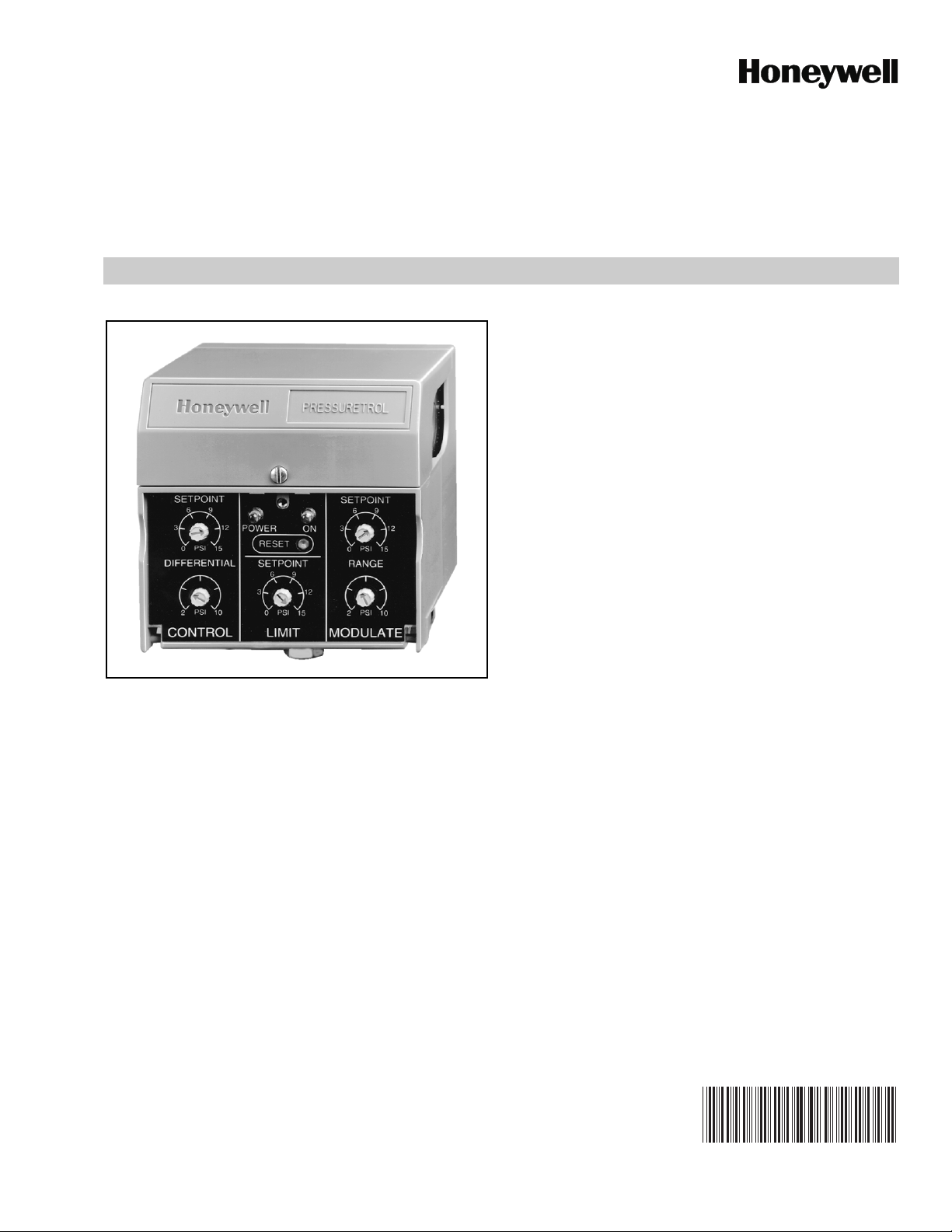
PressureTrol® Controller
FEATURES
• Use only with steam, air or noncombustible gases that
do not corrode the pressure sensing element.
• Models available in 15, 150 and 300 psi (103, 1034 and
2069 kPa) maximum setpoints.
• Light Emitting Diode (LED) indicators show power, call
for heat function and lockout status.
• Clear cover allows setpoint and differential to be read,
but not adjusted without opening the cover.
• Manual reset possible without opening the cover.
• Electronic maximum fixed stop limit.
PRODUCT DATA
APPLICATION
The P7810C PressureTrol® Controller is a line voltage
pressure controller for pressure systems up to 300 psi (2069
kPa). The P7810C provides On/Off Control, High Limit and 4
to 20 mA modulation.
Contents
Application 1
Features 1
Specifications 2
Installation 3
Wiring 4
Operation 6
Checkout 10
Troubleshooting 11
Service Information 11
65-0285—02
Page 2

P7810C PRESSURETROL® CONTROLLER
SPECIFICATIONS
Model:
P7810C PressureTrol® Controller with On/Off control,
modulate and safety high limit.
Electrical Ratings:
Power Input: 120 Vac (+10% /-15%), 50/60 Hz (±10%).
Power Consumption: See Table 1.
Output Impedance: 300 ohm maximum.
Table 1. Power consumption.
120 Vac
Rating 50 Hz 60 Hz
Watts 21.8 2.8
VA 7.0 7.0
Switch Contact Ratings: See Table 2.
Table 2. Switch contact ratings.
Relay Load Type 120 Vac
Control Amps Full Load (FLA) 9.8A
Amps Locked Rotor (ALR) 58.8A
Non-Inductive 10.0A
Alarm Pilot Duty 1.0A
Sensor Material: 304 stainless steel.
Pressure Connector: 1/2 in. NPT.
Case Material: Plastic.
Electrical Terminations: Screw terminals.
Accuracy: ±4.0 percent full scale output operating range,
over operating temperature.
Environmental Ratings:
Operating Temperature Range: 32°F to 140°F (0°C to 60°C).
Storage Temperature Range: -20°F to +150°F (-29°C to
+66°C).
Humidity: 5% to 95% relative humidity, noncondensing.
Vibration: 0.5G continuous maximum vibration.
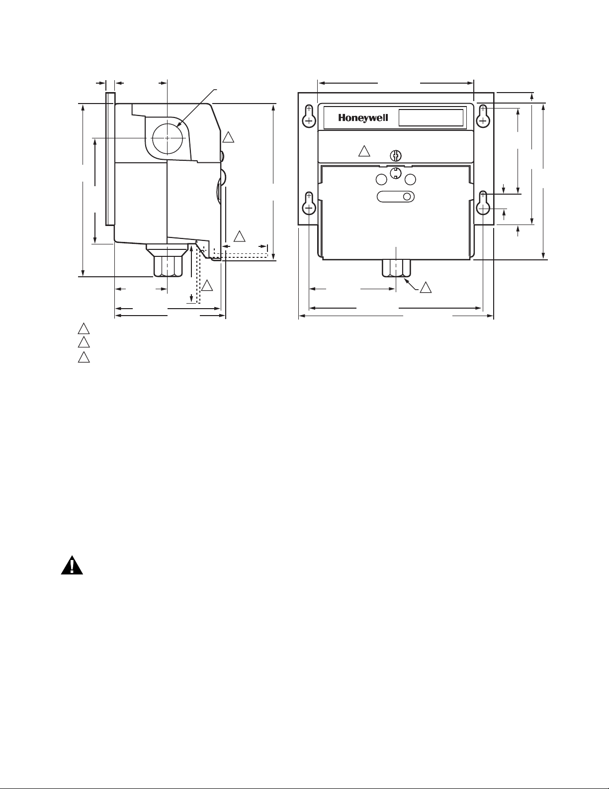
Dimensions: See Fig. 1.
Mounting Position: Upright, see Fig. 2.
Device Weight: 2.0 lb, 8 oz (1.15 kg).
Approvals:
Underwriters Laboratories Inc.: Listed; MP446-30-1.
Canadian Standards Association Certified; 158158-1355621.
Factory Mutual Approved: Approved; 3018936.
CSD-1 AFB (Control Safety Devices, Automatic Fired Boilers):
Acceptable.
FCC Class B, computing devices, part 15.
Accessories:
205860 Minimum Position Potentiometer for Series 70
Motors.
209731A Siphon Loop with 1/2 in. NPT threads.
4074EWD Mounting Bracket with six screws.
4074EDC or EED Bag Assembly to interface 4 to 20 mA with
Series 90 Firing Rate Motor.
Replacement Parts:
4074EWC Door Assembly with captive screw and adjusting
wrench (replacement part for P7810C).
4074EVP Door Wrench.
Pressure Ratings: See Table 3.
Table 3. Pressure ratings (psig).
Pressure Range Maximum Setpoint Differential Overpressure Burst Pressure
0 to 15 15 2 to 10 22.5 60
0 to 150 150 5 to 20 225 600
0 to 300 300 15 to 50 450 1200
ORDERING INFORMATION
When purchasing replacement and modernization products from your TRADELINE® wholesaler or distributor, refer to the
TRADELINE® Catalog or price sheets for complete ordering number.
If you have additional questions, need further information, or would like to comment on our products or services, please write or
phone:
1. Your local Honeywell Automation and Control Products Sales Office (check white pages of your phone directory).
2. Honeywell Customer Care
1885 Douglas Drive North
Minneapolis, Minnesota 55422-4386
In Canada—Honeywell Limited/Honeywell Limitée, 35 Dynamic Drive, Toronto, Ontario M1V 4Z9.
International Sales and Service Offices in all principal cities of the world. Manufacturing in Australia, Canada, Finland, France,
Germany, Japan, Mexico, Netherlands, Spain, Taiwan, United Kingdom, U.S.A.
65-0285—02 2
Page 3
P7810C PRESSURETROL® CONTROLLER
WARNING
1/4 (6) 2x1-5/8 (41)
5-1/4
(133)
2x
3-3/16
(81)
1-5/8 (41) 2-5/8 (67)
3-7/32 (82)
DIMENSIONS WITH DOOR IN OPEN POSITION.
1
22PIPE THREAD IS 1/4 INCH NATIONAL PIPE THREAD FOR P7810A,B; 1/2 INCH NATIONAL PIPE THREAD FOR P7810C,D.
WIRING COMPARTMENT ACCESS COVER.
3
2-17/32
(82)
3-3/8 (86)
1
2x27/32 (22)
DIAMETER
3
1
2-1/8 (55)
4-23/32
(120)
4-21/32 (119)
PRESSURETROL
3
RESET
2x5-1/4 (133)
5-29/32 (150)
¨
2-5/8
(67)
4
(102)
4-3/4
(120)
3/8
(10)
7/8
(22)
M11893B
Fig. 1. Approximate dimensions of P7810C PressureTrol® Controller in in. (mm).
INSTALLATION
When Installing This Product…
1. Read the instructions carefully. Failure to follow them
could damage the product or cause a hazardous
condition.
2. Check ratings (pressure and voltage, for example) and
description given in the specifications to make sure the
product is suitable for your application.
3. Installer must be a trained, experienced technician.
4. After installation is complete, check out product
operation as provided in these instructions.
Electrical Shock Hazard and Explosion Hazard.
Can cause severe injury, death or property damage.
1. Disconnect power supply before installation. More
than one disconnect may be involved.
2. Allow pressure to decrease to atmosphere from the
pressure vessel before removing old control.
3. Follow all installation and checkout procedures for
safe installation.
IMPORTANT
Do not remove the overpressure inlet seal until ready
to connect piping, to prevent contamination of inlet.
Location
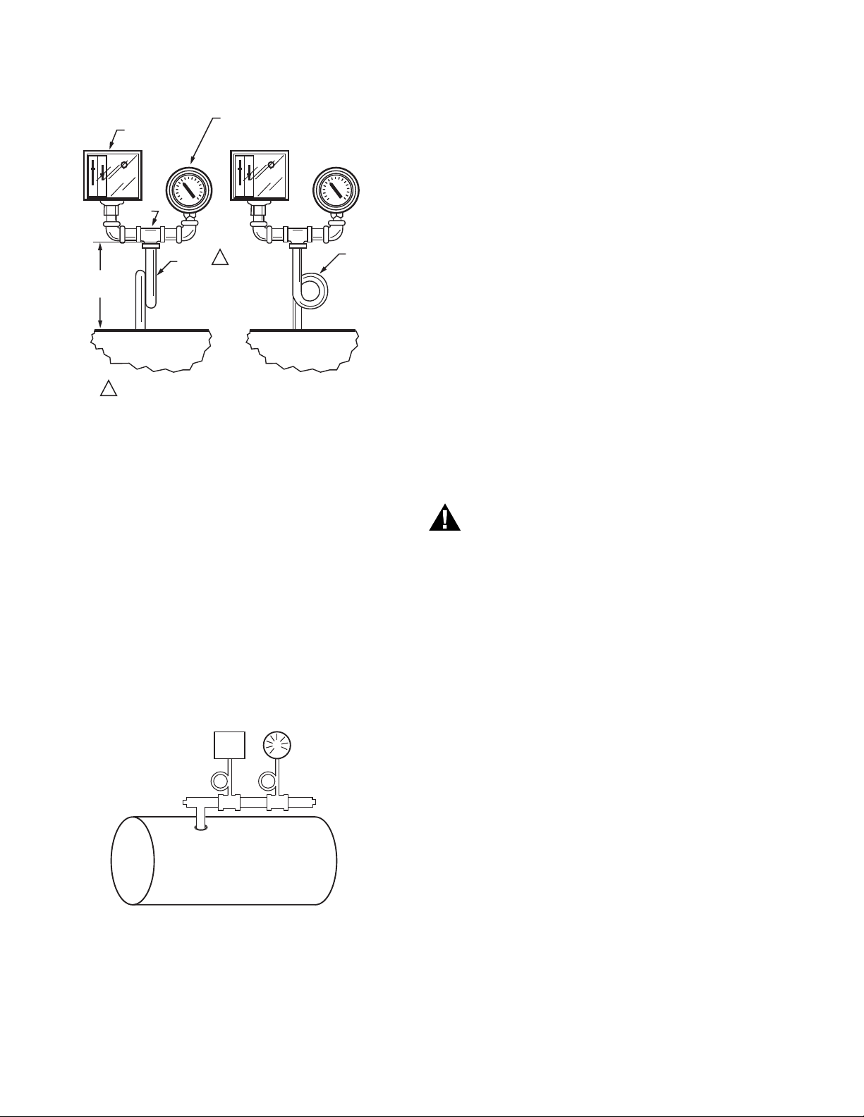
Install the P7810C PressureTrol® Controller above the boiler
water line when used with steam boilers. Connect the siphon
loop (part number 209731A or equivalent) between the
P7810C Controller and the boiler to prevent scale and
corrosive vapors from attacking the controller sensor element.
Mount the P7810C Controller next to the pressure gauge in the
manufacturer-provided fitting on the boiler. See Fig. 2 and 3.
Mount at a remote location to avoid excessive vibration, or
mount in a special mounting on a low water cutoff.
IMPORTANT
1. Locate the P7810C PressureTrol® Controller where
ambient temperature does not exceed 140°F (60°C).
2. Use pipe compound sparingly to avoid clogging the
hole in the pipe or the sensor element fitting.
3. Do not hand tighten the controller connection by holding the case. Use a wrench on the flats of the sensor
fitting to avoid leaks and damage to the case.
4. Level the controller for appearance.
5. Install the P7810C where the relative humidity never
reaches the saturation point. The P7810C is designed
to operate in a maximum 85 percent relative humidity,
continuous, noncondensing moisture environment.
Condensing moisture can cause a shutdown.
6. Do not install the P7810C where it could be subjected
to vibration in excess of 0.5G continuous maximum
vibration.
7. The P7810C is not designed to be weather-tight. If
installed outdoors, protect the P7810C with an
approved weather-tight enclosure.
3 65-0285—02
Page 4
P7810C PRESSURETROL® CONTROLLER
WARNING
4-1/2 TO 5-1/2
(114.3 TO 139.7)
BOILER
14026
STEAM TRAP
(SIPHON LOOP)
TEE
PRESSURE
GAUGE
PRESSURE
CONTROLLER
M8934A
1
1
1/4 IN. BLACK IRON PIPE WITH 1/4 - 18 NPT EXTERNAL
TRHEADS ON BOTH ENDS. BEND THE STEAM TRAP
(SIPHON LOOP) TO LEVEL THE CONTROLLER.
CORRECT
BOILER
2-1/4
(57.2)
DIA.
INCORRECT
P7810C
GAUGE
BOILER
M11891A
Fig. 2. Right and wrong mounting of steam trap (siphon
loop) for the P7810C, with approximate dimensions in in.
(mm).
4. If not convenient to mount the P7810C Controller next to
the pressure gauge, install a siphon loop in the
manufacturer-provided fitting.
5. If there is no fitting, mount the siphon loop at the boiler
manufacturer recommended location.
6. Attach the P7810C Controller directly to the siphon loop.
7. Level the P7810C Controller after the installation.
NOTE: The P7810C model requires 1/2 in. (13 mm)
mounting, either directly or on a siphon loop.
Remote Location Mounting
Excessive vibration at the boiler can damage the P7810C
Controller electronics.
1. Mount the P7810C Controller at a remote location to
eliminate vibration problems.
2. Make sure that all piping from the boiler is suitable to the
application and is solidly mounted.
3. Pitch the piping properly to drain the condensate back to
the boiler.
4. Mount the siphon loop between the remote piping and
the P7810C Controller.
5. Level the P7810C Controller after the installation.
WIRING
Mounting
Make all pipe connections in accordance with applicable local
standards. Use parallel jaw wrench to tighten P7810C
Controller hexagonal fitting to avoid leaks and damage to the
case.
Mounting P7810C Controller next to
pressure gauge
To mount the P7810C PressureTrol® Controller next to the
pressure gauge:
1. Remove the pressure gauge.
2. Replace the gauge with a siphon loop with tee connector
on top.
Fig. 3. Connecting P7810C PressureTrol® Controller to
3. Mount the P7810C Controller and pressure gauge on the
end of the tee.
steam boiler.
Electrical Shock Hazard.
Can cause severe injury, death or property damage.
Disconnect the power supply before wiring. More than
one disconnect may be involved.
All wiring must comply with applicable electrical codes,
ordinances and regulations. Use NEC Class 1 line voltage
wiring.
For nominal installation, use moisture-resistant No. 14 wire
(maximum size allowed) suitable for at least 167°F (75°C) or
194°F (90°C) for Flame Safeguard Primary Controls.
Use shielded wire for 4 to 20 mA modulating output and
terminate the shield to earth ground. Do not run these wires in
the same conduit as high voltage ignition wires.
All P7810C PressureTrol® Controllers have terminal screws
and 27/32 in. (22 mm) holes in both sides for conduit, cables
and wiring. Remove the top cover by loosening the screw at
the top of the P7810C Controller case.
Follow the burner or boiler manufacturer wiring diagram, if
provided. Make sure the loads do not exceed the contact
ratings in the Specifications section. See Fig. 4 for terminal
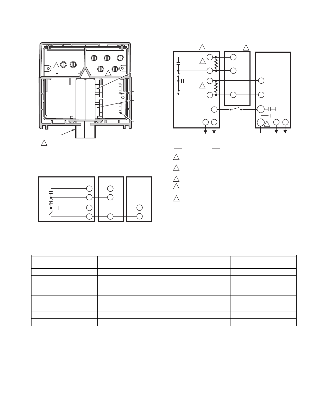
locations and Fig. 5 through 9 for typical wiring hookups.
Table 4 provides conversion wiring information for upgrading
older P7810 devices to newer series.
Replace the front cover after completing the wiring.
IMPORTANT
LIne voltage wiring terminals have changed between
Series 2 and Series 3 models.
65-0285—02 4
Page 5
P7810C PRESSURETROL® CONTROLLER
PROGRAMMER WIRING
HIGH FIRE
COMMON
MODULATE
LOW FIRE
F
-
–
+
MODUTROL®
MOTOR
P7810
CONTROLLER
M17130A
+
1
+mA -mA
(MODULATE)
1/2 IN. NPT
1 USE COPPER CONDUCTORS ONLY
OUT
NPT
Fig. 4. P7810C (Series 3 or greater)
PressureTrol® Controller.
LINE VOLTAGE
L2
1
ALARM
7800 SERIES
PROGRAMMER
GND
IN
1/4 IN. NPT
STEAM
PRESSURE
CONTROL
SENSOR
1/4 IN. NPT
STEAM
PRESSURE
HIGH LIMIT
CONTROL
SENSOR
M22024A
8K1
8K2
MODULATION
9K1
9K2
FIELD WIRING
1
7800 SERIES SHOWN. REFER TO SPECIFICATIONS PACKED WITH THE
PROGRAMMER FOR WIRING OF OTHER PRIMARY SAFETY CONTROLLERS.
2
MODUTROL® MOTOR MUST BE MODUTROL III OR MODUTROL IV,
SERIES 90, ELECTRONIC BALANCE RELAY TO OPERATE AS SHOWN.
3
PART OF 4074EDC OR 4074EED BAG ASSEMBLY ORDERED SEPARATELY.
4
LINE VOLTAGE TO PROGRAMMER AND CONTROLLER SHOULD
BE IN PHASE.
SEE CONVERSION WIRING TABLE FOR CONVERTING OLDER SERIES
5
DEVICES.
1
HIGH
3
COMMON
3
LOW
12
237
OHM
13
15
66.5
OHM
14
L2
120 VAC LINE
VOLTAGE
MODUTROL®
MOTOR
6
4
DEVICE WIRING
B
R
W
OTHER
LIMITS
P7810 PRESSURETROL®
2
CONTROLLER
–
4 TO 20mA
+
2K1
OUT
3K1
4
ALARM
1K1
IN
L2
120 VAC LINE
VOLTAGE
M13698
4 to 20 mA signal output (-) - - -
4 to 20 mA signal output (+) + + +
Limit string output to
programmer
L1 (Hot) COM
120 Vac Power Supply (L2) L2 L2 L2
120 Vac Power Supply (L1) L1
External Alarm Device — ALARM ALARM
a
If any additional/external limits are used, make sure they are inserted between the P7810C PressureTrol® Controller and the Pro-
grammer in the Limit string.
b When converting to a newer series from Series 1, L1 (120 Vac Power Supply) lead wire is not used, remove or wire-nut and tuck
away.
Fig. 6. Wiring diagram for typical P7810 installation,
Series 3 and greater, using Series 90 Modutrol® Motor.
Fig. 5. Firing rate wiring diagram using 4 to 20 mA
controller and series 70 Modutrol® Motor.
Table 4. Conversion wiring information for upgrading older P7810 devices to newer series.
Signal/Input Series 1 Terminals Series 2 Terminals
N.O. OUTPUT OUT
a
L1
bb
Series 3 or Greater
Terminals
a
IN
5 65-0285—02
Page 6
P7810C PRESSURETROL® CONTROLLER
14
LOW FIRE
15
MODULATE
13
COMMON
8K1
8K2
9K2
9K1
AUTO
MAN
66.5
OHM
237
OHM
12
HIGH FIRE
7800 SERIES
PROGRAMMER
W
M20568C
R
B
+
–
MODUTROL IV
MOTOR
CONTROLLER
P7810
(4-2O mA)
SERIES 90
1K
OHM
7800 SERIES SHOWN. REFER TO SPECIFICATIONS PACKED WITH THE
PROGRAMMER FOR WIRING OF OTHER PRIMARY SAFETY CONTROLLERS.
1
1
LOW FIRE
14
MODULATE
15
COMMON
8K1
8K2
9K2
9K1
AUTO
MAN
13
HIGH FIRE
7800 SERIES
PROGRAMMER
12
+
M20569C
205860
1
2
24V AC
MOD MOTOR
3
4
–
F
+
–
+
–
MODUTROL IV
MOTOR
CONTROLLER
P7810
(4-2O mA)
REMOTE
MINIMUM
POSITION
POTENTIONMETER
SERIES 70
(M7284)
1
1
7800 SERIES SHOWN. REFER TO SPECIFICATIONS PACKED WITH THE
PROGRAMMER FOR WIRING OF OTHER PRIMARY SAFETY CONTROLLERS.
ONLY 50% MOTOR AUTHORITY IS AVAILABLE WHEN USING THE 205860
POTENTIOMETER WITH THE SWITCH IN THE MANUAL POSITION.
2
2
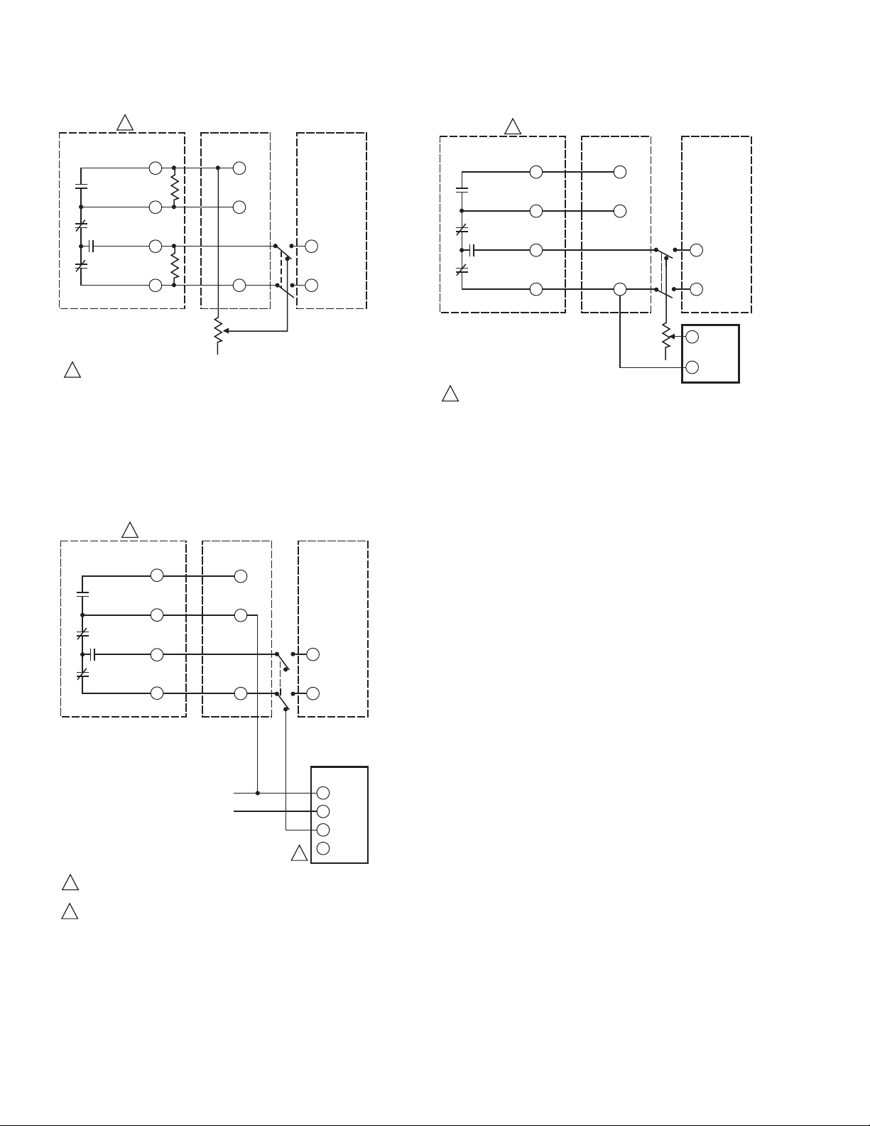
Fig. 7. Firing rate wiring diagram using P7810C
PressureTrol® Controller and Series 90 Modutrol® Motor
with manual position potentiometer and auto-manual
switch.
1
7800 SERIES
PROGRAMMER
HIGH FIRE
8K1
COMMON
8K2
MODULATE
9K1
9K2
LOW FIRE
1
7800 SERIES SHOWN. REFER TO SPECIFICATIONS PACKED WITH THE
PROGRAMMER FOR WIRING OF OTHER PRIMARY SAFETY CONTROLLERS.
12
13
15
14
SERIES 70
(M7284)
MODUTROL IV
MOTOR
F
–
+
OHM
5K
CONTROLLER
(4-2O mA)
AUTO
–
+
MAN
–
+
Fig. 9. Series 70 Motor with auto/manual switch
and 12 Vdc source.
OPERATION
P7810
12V DC
M20570C
Fig. 8. Series 70 Motor with auto/manual switch, using
205860 Minimum Position Potentiometer.
65-0285—02 6
The P7810 uses integral electronic pressure sensors to sense
pressure at the inlet through an internal manifold. The control
sensor connects to the internal manifold with 1/4 inch NPT
threads and provides the pressure signal to control a relay for
the on/off control function. The same sensor provides the
information for the 4 to 20 mA firing rate modulation output.
A separate integral electronic pressure sensor is required to
provide the high limit function. This sensor also connects to the
internal manifold with 1/4 inch NPT threads P7810C devices
contain two internal sensors and require a 1/2 inch NPT
mounting to the steam pressure header. Devices with high
limits lock out at setpoint and require manual reset when
pressure returns below the setpoint. Devices will not reset with
power interruption.
The P7810C has on/off function, 4 to 20 mA modulation control
output, and safety high limit function in one control. A 1/2 inch
NPT mounting is required to the steam pressure header.
Pressure On/Off Control Function
When pressure increases to the control setpoint, the control
relay contacts open. The relay contacts close when the
pressure decreases to a level at or below (differential) the
control range differential setting. This cycle continues until
power is removed, opening the relay. See Fig. 10.
Page 7
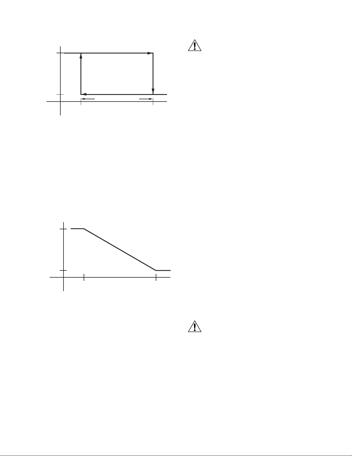
Fig. 10. P7810 on/off control function versus pressure.
CAUTION
CAUTION
ON
OFF
CONTROL
RELAY
(K)
CONTROL
RANGE
PRESSURE
CONTROL
SETPOINT
M4881B
DIFFERENTIAL SETTING
Modulate Control Function
When the pressure decreases to or below the modulation
setpoint, the current is 20 mA. The current remains constant at
all pressures below the modulation setpoint.
The modulation range is an additive value to the modulation
setpoint value.
When the pressure increases above the modulation setpoint,
the current decreases linearly until the modulation range point
is reached. The output current is 4 mA at and above this
pressure. See Fig. 11.
20 mA
MODULATION
CURRENT
4 mA
P7810C PRESSURETROL® CONTROLLER
Equipment Damage Hazard.
Exceeding pressure vessel limits can damage
equipment.
The Maximum Fixed Stop Limit pressure setting must
not exceed the maximum working pressure rating of
the pressure vessel. Adjust the Maximum Fixed Stop
Limit setting to the maximum working pressure rating
that is stamped on the pressure vessel by the
manufacturer.
b. To set the High Limit Setpoint. This is the desired
pressure value to which the P7810C control is
adjusted at at which it performs its intended function
(i.e., safety shutdown).
The High Limit Setpoint can be set lower than the internal
stored Maximum Fixed Stop Limit Value and will provide
system lockout at the knob setting. For example, the internal
stored Maximum Fixed Stop Limit Value is 12 psi and the knob
is set at 10 psi. System lockout is at 10 psi. The LED pattern
will be green on and yellow blinking slowly.
The High Limit Setpoint can be set above the internal stored
Maximum Fixed Stop Limit Value but it will have no functional
effect. For example, the internal stored Maximum Fixed Stop
Limit Value is 12 psi and knob is set at 14 psi. Lockout will
occur at 12 psi. The LED pattern will be green on and yellow
blinking fast.
When pressure increases to the high limit setpoint, the relay
contacts (1K1, 2K1) open and the P7810C indicates a safety
lockout by alternately flashing the yellow and green LED. The
P7810C remains in this condition until the manual reset button
(see Fig. 1) is pressed. The Alarm relay contacts (3K1) will
close, providing a 120 Vac output on the Alarm terminal.
Reset Switch Functions
The Reset Switch has the functions listed in Table 5.
MODULATION
SETPOINT
PRESSURE
Fig. 11. P7810C modulation current versus pressure.
Limit Function
The Limit potentiometer has two functions:
a. To set the Maximum Fixed Stop Limit. This is the
maximum pressure setting that the P7810C control
can be adjusted to and still perform its intended function (i.e., safety shutdown).
MODULATION
RANGE
M4882
P7810C PressureTrol® Controller Setup
For the P7810C PressureTrol® Controllers with more than one
function (control, modulate and high limit), adjust setpoints and
differentials separately for each function.
Equipment Damage Hazard.
Improper setting of control setpoint and control
range knob errors can damage the P7810C.
Adjust setpoints and differentials using the knobs on
the front of the P7810C PressureTrol® Controller.
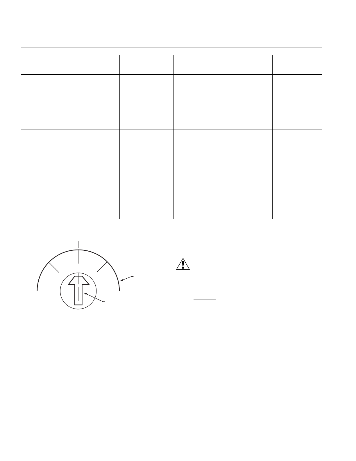
Set the knobs to the desired points by aligning the center of the
knob arrow with the desired mark on the scale plate. See Fig.
12.
7 65-0285—02
Page 8
P7810C PRESSURETROL® CONTROLLER
CAUTION
DIAL ARROW
SCALE
PLATE
M4880A
Table 5. Reset switch function, P7810C.
Reset Switch
Action Lockout Unconfigured
Press and
Continuously Hold.
Press and release. Clear the fault code
Blink existing fault
code until the reset
switch is released.
and reset the
P7810C.
Both LED turn on after
three seconds,
indicating the
Maximum Fixed Stop
Limit Value has been
stored. Wait for up to
30 seconds for a
release. Enter lockout
after 30 seconds.
Press and release of
the Reset Switch
within three seconds
is ignored. If the Reset
Switch is pressed for
more than three
seconds, both LED
turn on and the
Maximum Fixed Stop
Limit Value is stored
into non-volatile (NV)
memory. Upon
release, the device
will recycle and enter
normal operation.
P7810C Modes of Operation
(Run) Normal
Operation
The green LED
turns off and the
yellow LED turns
on, waiting until the
reset switch is
released.
Resets the control. Enter normal
Both LED turn on.
Wait for up to 30
seconds for a
release. Lockout
after 30 seconds. If
released within 30
seconds, enter
normal operation.
operation.
Power-up
(Configuration
Time Expired)
Power-up
(Configuration
Time Not Expired)
Enter unconfigured
mode of operation.
Enter unconfigured
mode of operation.
Fig. 12. Setting control setpoint and control range knobs.
IMPORTANT
P7810C devices must set Maximum Fixed Stop Limit
Value function first.
Setting Maximum Fixed Stop Limit Value
Equipment Damage Hazard.
Exceeding pressure vessel limits can damage
equipment.
The Maximum Fixed Stop Limit pressure setting
must not
rating of the pressure vessel. Adjust the Maximum
Fixed Stop Limit setting to maximum working
pressure rating that is stamped on the pressure vessel
by the manufacturer.
IMPORTANT
The Maximum Fixed Stop LImit Value must be
programmed first for the P7810C to operate.
1. Initial Startup—Maximum Fixed Stop Limit Value is
unprogrammed.
a. Green LED (Control LED)—Blinking rapidly (1/2 sec-
b. Yellow LED (Power LED)—On steady and bright.
2. Setting the Maximum Fixed Stop Limit Value.
a. Monitor the 4 to 20 mA output. Long filtering delays
b. Turn the Limit Setpoint knob to the desired setting
exceed the maximum working pressure
ond on, 1/2 second off).
cause a lag between the 4 to 20 mA output and the
limit setting, i.e., 20 to 25 seconds for a full-scale
change.
and confirm by comparing the current noted to the
corresponding reading in Table 6. Ensure that the
mA output is stable before using the value.
65-0285—02 8
Page 9

P7810C PRESSURETROL® CONTROLLER
c. Press and hold the Reset Switch.
d. Release the Reset Switch when both LED turn on.
e. The Maximum Fixed Stop Limit Value is set and the
device will recycle and attempt to enter the Run
mode.
f. After an accumulated run time (Call for Heat) of one
hour (Series 1 and 2) or eight hours (Series 3 or
greater), the Maximum Fixed Stop Limit Value setting
will be permanently stored in the P7810C memory.
Changing the Maximum Fixed Stop Limit Value
setting after this time will then be ineffective.
Table 6. Setting maximum fixed stop limit value—
current readings.
15 psi 150 psi 300 psi 4 to 20 mA Output
00 04.00
110205.07
220406.13
330607.20
440808.27
550 1009.33
6 60 120 10.40
77014011.47
8 80 160 12.53
9 90 180 13.60
10 100 200 14.67
11 11 0 22 0 15 .73
12 120 240 16.80
13 130 260 17.87
14 140 280 18.93
15 150 300 20.00
Changing the Maximum Fixed Stop Limit Value Setting (if Run Time is less than one hour [For Series 1 and 2] or less than eight hours [For Series 3 or greater])
1. Remove power from the P7810C.
2. Press and hold the Reset Switch, then apply power to
the P7810C.
3. When the green LED blinks rapidly, release the Reset
Switch.
4. Follow the steps in Setting the Maximum Fixed Stop
Limit Value, above.
NOTE: If both LED turn on, the configuration timer (one hour)
has expired. Release the Reset Switch and continue
normal operation. Changing the Maximum Fixed Stop
Limit Value Setting is no longer allowed.
Checking the Maximum Fixed Stop Limit Value (Stored in Memory)
1. Record the original location of the Limit setpoint knob.
Make sure that the Limit setpoint knob is set (moved to)
a lower value than the Maximum Fixed Stop Limit Value
setpoint. The green LED will be reflective of the call for
heat status and the yellow LED will blink slowly.
IMPORTANT
Do not decrease the Limit Setpoint knob far enough
to cause a lockout.
2. Very slowly increase the Limit setpoint knob until the yel-
low LED begins to blink fast. The current position of the
Limit setpoint now represents the Maximum Fixed Stop
Limit Value setpoint stored in memory.
3. Return the Limit setpoint knob to the original location
(step 1).
Setting High Limit Setpoint
After the Maximum Fixed Stop Limit Value has been stored into
memory, adjust the Limit setpoint knob to the desired pressure
value at which safety shutdown (lockout) will occur when the
vessel pressure exceeds this setpoint value.
NOTE: The High Limit setpoint value can be less than or
equal to the Maximum Fixed Stop Limit Value but cannot be set to a value higher than the Maximum Fixed
Stop Limit Value.
Pressure On/Off Control
Adjust the setpoint and differential using the potentiometer
knobs on the front of the controller. The differential is a
subtractive value from the setpoint adjustment. The upper
operating point is determined by the control setpoint, while the
lower operating point is determined by the control range setting
(control setpoint minus the differential setting).
Set the potentiometer knobs to the desired point by aligning
the center of the arrow on the potentiometer knob with the
desired mark on the scale plate. See Fig. 12.
Yellow LED ON constantly indicates power applied; green LED
On indicates closed contact or call for heat.
Modulate Control
The P7810C adds 4 to 20 mA modulation output and uses two
additional potentiometers. The pressure sensor output is fed to
an error and gain amplifier to perform the modulation
determined by the control potentiometer settings.
The potentiometer knobs mounted on the P7810C face adjust
the current output for a given set of pressures.
The modulation range is an additive value to the modulation
setpoint value.
LED Display (Tables 7 and 8)
The yellow LED is always lit with power applied to the P7810C
PressureTrol® Controller. The microprocessor changes the
brightness of the yellow LED to indicate normal operation,
turns the green LED on and off to indicate call for heat status
and flashes both LED to indicate a fault.
NOTE: The P7810C must be powered and in the Run mode.
NOTE: The term “flashing” means on/off/on/off for the green
LED and bright/dim/bright/dim for the yellow LED.
9 65-0285—02
Page 10
P7810C PRESSURETROL® CONTROLLER
WARNING
Press and hold the Reset Switch to access internal
diagnostics. The green (right) LED will flash a series of long
followed by a series of short flashes. Count the long and short
flashes and check the fault code table (Table 8) for information.
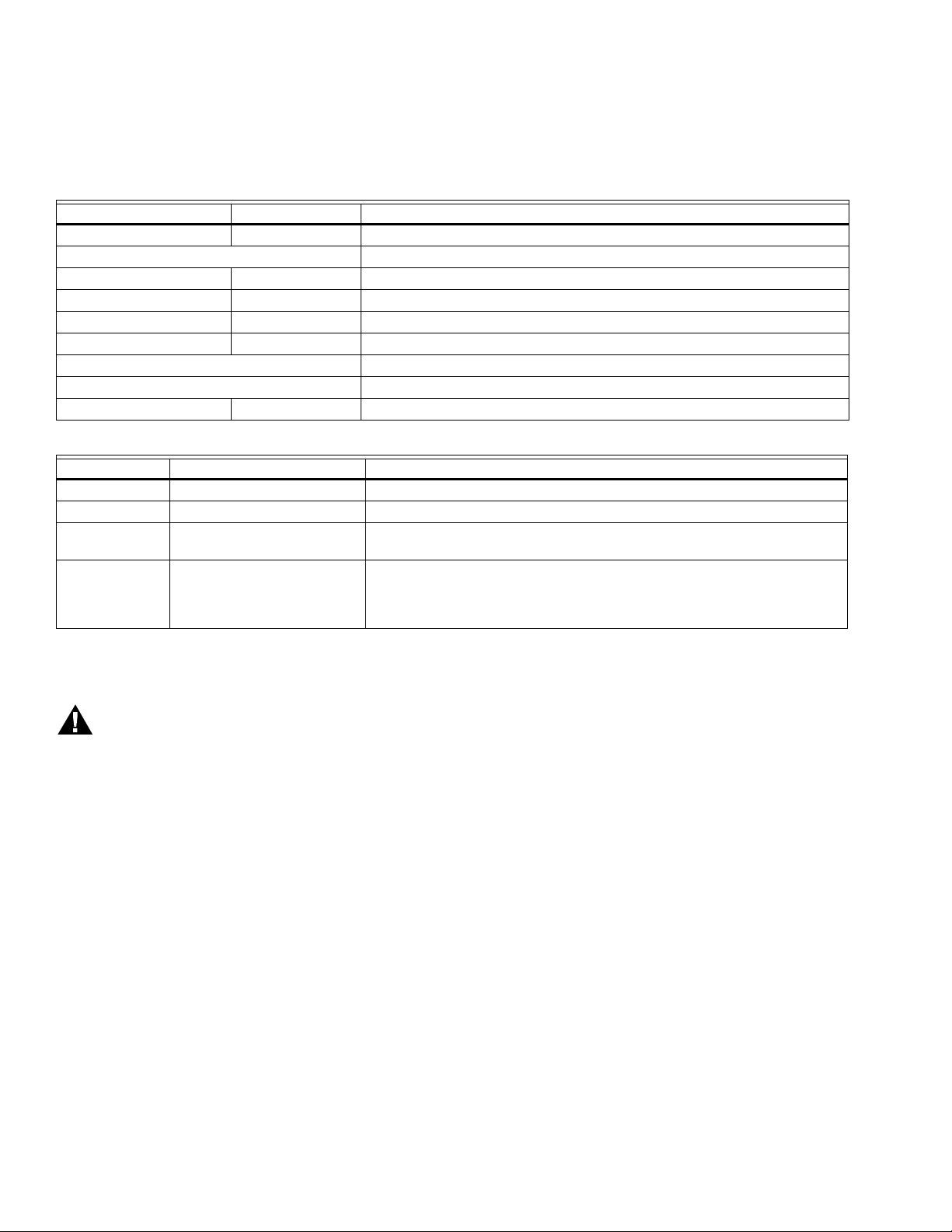
Table 7. P7810 blink bodes.
Yellow Green Control State
Off Off Device off.
No LED blinking Device on, Central Processing Unit (CPU) malfunction.
Slow Blink Off Run mode, output off, Limit potentiometer setpoint used.
Slow Blink On Run mode, output on, Limit potentiometer setpoint used.
Fast Blink Off Run mode, output off, Internal Maximum Fixed Stop Value setting used.
Fast Blink On Run mode, output on, Internal Maximum Fixed Stop Value setting used.
Alternating Fast Blinks Lockout, output off, high limit exceeded, Alarm output engaged.
Simultaneous Fast Blinks Lockout, output off, internal fault, Alarm output engaged.
On, Bright Fast Blink Output off, internal Maximum Fixed Stop Value setting not set.
Table 8. LED fault codes and recommended troubleshooting.
Fault Code System Failure Recommended Troubleshooting
11 High Limit Setpoint Exceeded. When pressure in vessel returns to normal, P7810C can be reset.
12-32, 71-90, 92 Internal fault. Reset P7810C; if same fault occurs again, replace P7810C.
51, 54, 61 Internal fault—internal relays
welded.
52-69, 91 Relay fault. Verify that no voltage potential exists on Output terminal. If code repeats after
Verify loads do not exceed rating of P7810C contacts, then replace P7810C.
normal operation, look for back feed of voltage greater than 50V (ac or dc)
any time during boiler sequence. Replacing P7810C will only result in same
lockout on new control.
For example: four long and three short flashes is code 43. If
you miss the code the first time, keep holding the Reset Switch
down and the code will repeat. Letting go of the Reset Switch
clears the fault information and resets the P7810.
CHECKOUT
Electrical Shock Hazard and Explosion Hazard.
Can cause severe injury, death or property damage.
1. Line voltage is present at the P7810C and all
controller circuits. Use extreme care during
checkout.
2. This checkout procedure disables the Safety High
Limit function.
IMPORTANT
1. Do not put the system into service until all applicable
tests described in the Checkout section of the
instructions for the primary safety control and any
additional tests required by the burner or boiler
manufacturer are satisfactorily completed.
2. Close all manual fuel shutoff valves when trouble
occurs.
After installation and wiring, check out the P7810C
PressureTrol® Controller with the system in operation.
Checkout
1. Allow the system to stabilize.
2. Observe the operation of the P7810C while raising and
lowering the setpoint. Pressure increases when the
setpoint is increased and decreases when the setpoint is
decreased.
3. Check the make and break points of the P7810C. If they
do not agree with a separate, accurately calibrated
pressure gauge, make a slight adjustment according to
the scale. Use accurate pressure testing equipment
when checking out the P7810C. Do not rely on
inexpensive gauges. The P7810C is carefully calibrated
at the factory.
Test the P7810C PressureTrol® Controller as follows:
NOTE: Make sure the P7810C is operating properly by
checking the LED indicators. If the P7810C LED
indicate a lockout condition, press the manual Reset
Switch.
NOTE: This procedure simulates pressure changes using
knob setpoint adjustments. Make knob adjustments
very slowly because of filtering delays within the
P7810C (20 to 25 seconds for full scale changes).
Inaccuracy can result if knob adjustments are not
made very slowly. To observe actual P7810C control
accuracy, set the knobs to normal operating values.
Compare the knob settings to the boiler pressure
readings where P7810C actions occur.
To check the control setpoint of the P7810C:
65-0285—02 10
Page 11

P7810C PRESSURETROL® CONTROLLER
WARNING
CAUTION
WARNING
1. Note the boiler pressure by checking the boiler pressure
gauge. To properly perform these tests, the boiler
pressure should be near the middle of the P7810C
pressure range.
2. Turn the P7810C Limit setpoint knob fully clockwise to
make sure this limit does not interfere during steps 4 and
5. This setting must be returned to the proper operating
position when return the system to normal operation.
3. Check the control setpoint and control differential.
4. Set the control differential knob to the center of its range.
5. Turn the control setpoint knob fully counterclockwise and
make sure the P7810C control circuit is open and the
green LED is off (no call for heat).
6. Read the boiler pressure gauge and add this number to
the control differential setting.
7. Turn the control setpoint knob slowly clockwise and
make sure the control circuit closes and the P7810C
indicates a call for heat (green LED on) when the
P7810C control setpoint passes through the value determined in step 6.
8. Turn the control setpoint knob slowly counterclockwise
and make sure the control circuit opens and the P7810C
no longer indicates a call for heat (green LED off) when
the control setpoint passes through the boiler pressure
gauge value.
Check the modulation setpoint and modulation range of the
P7810C as follows:
1. Set the P7810C modulation range knob to the center of
the range.
2. Turn the modulation setpoint knob fully clockwise and
make sure the firing rate motor travels to the fully open
position (boiler is firing).
3. Turn the modulation knob slowly counterclockwise and
make sure the firing rate motor starts moving toward the
closed position when the modulation setpoint passes
through the boiler pressure gauge value. (Alternately,
make sure the current starts decreasing toward 4 mA.)
4. Determine the pressure point at which minimum
modulation output will occur by checking the boiler
pressure gauge and subtracting the modulation range
knob setting (at midpoint).
5. Turn the modulation setpoint knob slowly
counterclockwise and make sure the firing rate motor
continues to move to the closed position. Make sure the
firing rate motor reaches the lowfire position when the
modulation setpoint reaches the pressure point identified
in step 4 above. (Alternately, make sure the measured
current decreases gradually toward 4 mA.)
Check the limit setpoint as follows (boiler pressure required):
1. Turn the control setpoint knob clockwise until the control
circuit closes. Make sure the yellow LED is flashing and
the green LED is on, indicating normal operation with a
call for heat.
2. Turn the limit setpoint knob slowly counterclockwise and
make sure that the P7810C opens the circuit and
indicates a safety lockout by alternately flashing the
yellow and green LED (see LED Display section) when
the limit setpoint passes through the boiler pressure
gauge value.
3. Make sure that the Alarm output is energized.
Check for normal system operation as follows:
1. Set all knobs to the required operating position.
2. Press the Reset Switch to clear the safety lockout
condition.
3. Start the system and observe the operation through at
least one complete cycle to make sure the P7810C
functions properly as described in the Operation section.
TROUBLESHOOTING
Electrical Shock Hazard.
Can cause severe injury, death or property damage.
Line voltage is present in the P7810C and in all
controller circuits. Use extreme care when
troubleshooting.
To determine control malfunctions, use checkout procedures
as listed in the Checkout section.
Equipment Damage Hazard.
Can cause equipment damage or improper
operation.
Do not put the system into service until you have
satisfactorily completed all applicable tests described in
this checkout section, and also all tests in the Checkout
section of the applicable instructions for the primary
safety control and any other tests the burner and boiler
manufacturer require.
SERVICE INFORMATION
Electrical Shock Hazard.
Can cause severe injury, death or property damage.
1. Only qualified Flame Safeguard technicians should
attempt to service Flame Safeguard controls and
burners.
2. Line voltage is present in the electrical circuits to the
P7810C PressureTrol® Controller. Open the master
electrical switch before replacing the device. More
than one power supply disconnect may be involved.
Scheduled Inspection and Maintenance
Calibration
The P7810C PressureTrol® Controller was carefully calibrated
during manufacturing and does not require field calibration.
Maintenance
Keep the cover of the P7810C PressureTrol® Controller in
place at all times to protect the internal components from dust,
dirt and physical damage. Routine maintenance consists of
occasional inspection and removal of accumulated dirt and
dust. Make sure the P7810C PressureTrol® Controller is
functioning properly by performing an operation check of the
entire system during routine maintenance checks.
11 65-0285—02
Page 12

P7810C PRESSURETROL® CONTROLLER
Automation and Control Solutions
Honeywell International Inc.
1985 Douglas Drive North
Golden Valley, MN 55422
Honeywell Limited-Honeywell Limitée
35 Dynamic Drive
Toronto, Ontario M1V 4Z9
customer.honeywell.com
® U.S. Registered Trademark
© 2009 Honeywell International Inc.
65-0285—02 K.K. Rev. 12-09
Printed in U.S.A.
 Loading...