

Page 1
Orbit 7120plus/7190g
Hybrid Presentation Scanner
User Guide
Page 2

Disclaimer
Honeywell International Inc. (“HII”) reserves the right to make changes in specifications and other information contained in
this document without prior notice, and the reader should in all cases consult HII to determine whether any such changes
have been made. The information in this publication does not represent a commitment on the part of HII.
HII shall not be liable for technical or editorial errors or omissions contained herein; nor for incidental or consequential
damages resulting from the furnishing, performance, or use of this material. HII disclaims all responsibility for the selection and use of software and/or hardware to achieve intended results.
This document contains proprietary information that is protected by copyright. All rights are reserved. No part of this document may be photocopied, reproduced, or translated into another language without the prior written consent of HII.
2017 Honeywell International Inc. All rights reserved.
Web Address:
Microsoft® Windows®, Windows NT®, Windows 2000, Windows ME, Windows XP, and the Windows logo are trademarks or
registered trademarks of Microsoft Corporation.
Other product names or marks mentioned in this document may be trademarks or registered trademarks of other companies and are the property of their respective owners.
For patent information, refer to www.hsmpats.com.
www.honeywellaidc.com
Page 3

TABLE OF CONTENTS
Customer Support ........................................................................................................................ xi
Technical Assistance ............................................................................................................. xi
Product Service and Repair ................................................................................................ xi
Limited Warranty .................................................................................................................... xi
Send Feedback ........................................................................................................................ xi
Chapter 1 - Get Started ....................................................................................1
About This Manual......................................................................................................................... 1
Unpack Your Device....................................................................................................................... 1
Power Information ......................................................................................................................... 1
Connect the Device........................................................................................................................ 2
Connect with USB....................................................................................................................2
Connect with Keyboard Wedge .......................................................................................... 2
Connect with RS232 Serial Port ........................................................................................ 4
Connect with RS485............................................................................................................... 5
Reading Techniques...................................................................................................................... 5
Menu Bar Code Security Settings............................................................................................ 5
Set Custom Defaults ..................................................................................................................... 6
Reset the Custom Defaults......................................................................................................... 6
Chapter 2 - Program the Interface ................................................................ 7
Introduction...................................................................................................................................... 7
Program the Interface - Plug and Play.................................................................................. 7
Keyboard Wedge............................................................................................................................. 7
Orbit 7120plus/7190g User Guide i
Page 4

Laptop Direct Connect .................................................................................................................8
RS232 Serial Port............................................................................................................................8
RS485..................................................................................................................................................8
RS485 Packet Mode................................................................................................................9
USB IBM SurePos ........................................................................................................................10
USB PC or Macintosh Keyboard ............................................................................................10
USB HID........................................................................................................................................... 11
USB Serial .......................................................................................................................................11
CTS/RTS Emulation .............................................................................................................11
ACK/NAK Mode......................................................................................................................11
Remote MasterMind™ for USB............................................................................................... 12
Verifone® Ruby Terminal............................................................................................................12
Gilbarco® Terminal.......................................................................................................................13
Honeywell Bioptic Aux Port .....................................................................................................13
Datalogic™ Magellan® Aux Port..............................................................................................13
NCR Bioptic Aux Port..................................................................................................................14
Wincor Nixdorf Terminal...........................................................................................................14
Wincor Nixdorf Beetle™ Terminal.......................................................................................... 14
Wincor Nixdorf RS232 Mode A...............................................................................................15
Keyboard Country Layout.........................................................................................................15
Keyboard Wedge Modifiers......................................................................................................23
ALT Mode..................................................................................................................................23
Keyboard Style ..............................................................................................................................23
Keyboard Conversion .................................................................................................................24
Control Character Output.........................................................................................................25
Keyboard Modifiers.....................................................................................................................25
RS232 Modifiers ..........................................................................................................................27
RS232 Baud Rate ..................................................................................................................27
RS232 Word Length: Data Bits, Stop Bits, and Parity ............................................28
RS232 Receiver Time-Out .................................................................................................29
RS232 Handshaking............................................................................................................29
ii Orbit 7120plus/7190g User Guide
Page 5

RS232 Timeout.......................................................................................................................30
XON/XOFF ...............................................................................................................................30
ACK/NAK...................................................................................................................................31
Scanner to Bioptic Communication .....................................................................................31
Scanner-Bioptic Packet Mode..........................................................................................31
Scanner-Bioptic ACK/NAK Mode....................................................................................32
Scanner-Bioptic ACK/NAK Timeout ..............................................................................32
Chapter 3 - Input/Output Settings .............................................................33
Power Up Beeper..........................................................................................................................33
Good Read and Error Indicators.............................................................................................33
Beeper – Good Read .............................................................................................................33
Beeper Volume – Good Read ............................................................................................34
Beeper Pitch – Good Read .................................................................................................34
Beeper Pitch – Error .............................................................................................................35
Beeper Duration – Good Read..........................................................................................35
LED – Good Read...................................................................................................................35
Number of Beeps – Good Read........................................................................................36
Number of Beeps – Error....................................................................................................36
Good Read Delay....................................................................................................................36
User-Specified Good Read Delay ....................................................................................37
Serial Trigger Mode .....................................................................................................................37
Read Time-Out........................................................................................................................37
Presentation Mode ......................................................................................................................37
Presentation Idle Mode.......................................................................................................38
Presentation LED Behavior after Decode....................................................................38
Presentation Sensitivity ......................................................................................................38
Presentation Centering.......................................................................................................39
Poor Quality Codes......................................................................................................................41
Poor Quality 1D Codes ........................................................................................................41
Poor Quality PDF Codes......................................................................................................41
Mobile Phone Read Mode ........................................................................................................42
Reread Delay ..................................................................................................................................42
User-Specified Reread Delay ............................................................................................43
Orbit 7120plus/7190g User Guide iii
Page 6

2D Reread Delay ....................................................................................................................43
Illumination Lights......................................................................................................................43
Host Acknowledgment...............................................................................................................44
Host ACK On/Off ...................................................................................................................45
Host ACK Timeout................................................................................................................. 45
Host ACK Responses............................................................................................................45
Character Activation Mode ......................................................................................................46
Activation Character ............................................................................................................46
End Character Activation After Good Read.................................................................47
Character Activation Timeout ..........................................................................................47
Character Deactivation Mode.................................................................................................48
Deactivation Character....................................................................................................... 48
D/E Character (Disable/Enable) ........................................................................................... 48
Beep on BEL Character ............................................................................................................. 49
Centering ........................................................................................................................................49
Single Code Centering ........................................................................................................49
Custom Centering Settings............................................................................................... 49
Preferred Symbology..................................................................................................................51
High Priority Symbology ....................................................................................................52
Low Priority Symbology ...................................................................................................... 52
Preferred Symbology Time-out........................................................................................52
Preferred Symbology Default ........................................................................................... 53
Output Sequence Overview .....................................................................................................53
Output Sequence Editor.....................................................................................................53
To Add an Output Sequence .............................................................................................53
Other Programming Selections.......................................................................................54
Output Sequence Example................................................................................................54
Output Sequence Editor.....................................................................................................55
Partial Sequence ...................................................................................................................56
Require Output Sequence .................................................................................................56
No Read ...........................................................................................................................................57
Video Reverse ................................................................................................................................57
Working Orientation ...................................................................................................................58
iv Orbit 7120plus/7190g User Guide
Page 7

Chapter 4 - Data Edit ......................................................................................59
Prefix/Suffix Overview ...............................................................................................................59
Points to Keep In Mind ........................................................................................................59
Add a Prefix or Suffix............................................................................................................60
Add a Tab Suffix to All Symbologies ...............................................................................60
Clear One or All Prefixes or Suffixes...............................................................................61
To Add a Line Feed/Carriage Return Suffix to All Symbologies..........................61
Add an ETX Suffix to All Symbologies ...........................................................................61
Add an STX Prefix to All Symbologies............................................................................61
Prefix Selections...........................................................................................................................62
Suffix Selections...........................................................................................................................62
Function Code Transmit............................................................................................................62
Intercharacter, Interfunction, and Intermessage Delays .............................................63
Intercharacter Delay.............................................................................................................63
User Specified Intercharacter Delay ..............................................................................63
Interfunction Delay ...............................................................................................................64
Intermessage Delay..............................................................................................................64
Chapter 5 - Data Format ................................................................................65
Data Format Editor Introduction ...........................................................................................65
Add a Data Format.......................................................................................................................66
Other Programming Selections.......................................................................................67
Terminal ID Table...................................................................................................................68
Data Format Editor Commands .............................................................................................68
Send Commands ...................................................................................................................68
Move Commands...................................................................................................................73
Search Commands................................................................................................................75
Miscellaneous Commands ................................................................................................77
Data Formatter..............................................................................................................................81
Primary/Alternate Data Formats ...........................................................................................82
Single Scan Data Format Change...................................................................................82
Orbit 7120plus/7190g User Guide v
Page 8

Chapter 6 - Symbologies............................................................................... 85
All Symbologies ............................................................................................................................86
Message Length Description.................................................................................................. 86
Codabar ...........................................................................................................................................87
Code 39............................................................................................................................................ 89
Interleaved 2 of 5 .........................................................................................................................93
NEC 2 of 5.......................................................................................................................................95
NEC 2 of 5 Message Length.............................................................................................96
Code 93............................................................................................................................................ 96
Straight 2 of 5 Industrial (three-bar start/stop)..............................................................98
Straight 2 of 5 IATA (two-bar start/stop)............................................................................99
Matrix 2 of 5................................................................................................................................ 100
Code 11......................................................................................................................................... 101
Code 128...................................................................................................................................... 102
ISBT 128 Concatenation ................................................................................................. 102
GS1-128 ....................................................................................................................................... 104
Telepen.......................................................................................................................................... 105
UPC-A............................................................................................................................................ 106
UPC-A/EAN-13 with Extended Coupon Code.............................................................. 108
Coupon GS1 DataBar Output .............................................................................................. 109
UPC-E0 ......................................................................................................................................... 110
UPC-E0 Addenda Required............................................................................................ 110
UPC-E1 ......................................................................................................................................... 112
EAN/JAN-13 ............................................................................................................................... 113
ISBN Translate..................................................................................................................... 120
EAN/JAN-8.................................................................................................................................. 120
MSI.................................................................................................................................................. 122
Plessey Code............................................................................................................................... 124
GS1 DataBar Omnidirectional............................................................................................. 126
GS1 DataBar Limited .............................................................................................................. 126
GS1 DataBar Expanded ......................................................................................................... 127
vi Orbit 7120plus/7190g User Guide
Page 9

Trioptic Code ...............................................................................................................................127
Codablock A.................................................................................................................................128
Codablock F.................................................................................................................................129
Label Code...................................................................................................................................129
PDF417 .........................................................................................................................................130
MacroPDF417............................................................................................................................131
MicroPDF417 .............................................................................................................................131
GS1 Composite Codes ............................................................................................................132
GS1 Emulation ...........................................................................................................................133
TCIF Linked Code 39 (TLC39)..............................................................................................134
QR Code ........................................................................................................................................134
Data Matrix ..................................................................................................................................136
MaxiCode......................................................................................................................................137
Aztec Code ...................................................................................................................................138
Chinese Sensible (Han Xin) Code.......................................................................................139
Postal Codes - 2D......................................................................................................................140
Planet Code Check Digit..................................................................................................144
Postnet Check Digit...........................................................................................................144
Australian Post Interpretation.......................................................................................144
Postal Codes - Linear ..............................................................................................................145
China Post (Hong Kong 2 of 5)......................................................................................145
Korea Post..............................................................................................................................146
Chapter 7 - EAS Settings ............................................................................149
EAS Considerations .................................................................................................................149
EAS Deactivation.......................................................................................................................149
EAS Deactivation Zone.....................................................................................................150
EAS Controller............................................................................................................................150
EAS Mode of Operation..........................................................................................................150
EAS Interlocked Duration Timeout..............................................................................151
Checkpoint® Systems ..............................................................................................................151
Orbit 7120plus/7190g User Guide vii
Page 10

Chapter 8 - Imaging Commands ...............................................................153
Single-Use Basis....................................................................................................................... 153
Command Syntax .....................................................................................................................153
Image Snap - IMGSNP............................................................................................................ 154
IMGSNP Modifiers............................................................................................................. 154
Image Ship - IMGSHP............................................................................................................. 157
IMGSHP Modifiers............................................................................................................. 158
Image Size Compatibility ................................................................................................166
Intelligent Signature Capture - IMGBOX ........................................................................167
Signature Capture Optimize.......................................................................................... 167
IMGBOX Modifiers............................................................................................................. 168
Chapter 9 - Utilities......................................................................................173
Add a Test Code I.D. Prefix to All Symbologies.............................................................. 173
Show Decoder Revision.......................................................................................................... 173
Show Scan Driver Revision.................................................................................................... 173
Show Software Revision ......................................................................................................... 174
Show Data Format.................................................................................................................... 174
Test Menu .................................................................................................................................... 174
TotalFreedom.............................................................................................................................. 174
Application Plug-Ins (Apps) ................................................................................................. 175
EZConfig Cloud for Scanning Introduction ................................................................... 175
EZConfig Cloud for Scanning Operations................................................................ 176
Install EZConfig Cloud for Scanning.......................................................................... 176
Reset the Factory Defaults.................................................................................................... 177
Chapter 10 - Swivel Base Accessory.........................................................179
Mount the Swivel Base ........................................................................................................... 180
Use the Swivel Base ................................................................................................................. 180
Chapter 11 - Serial Programming Commands.......................................183
Conventions................................................................................................................................ 183
viii Orbit 7120plus/7190g User Guide
Page 11

Menu Command Syntax.........................................................................................................183
Query Commands .....................................................................................................................184
Trigger Commands...................................................................................................................186
Reset the Custom Defaults ...................................................................................................187
Menu Commands .....................................................................................................................188
Chapter 12 - Product Specifications........................................................209
Orbit 7120plus Product Specifications............................................................................209
Orbit 7190g Product Specifications..................................................................................210
Standard Connector Pinouts................................................................................................212
Keyboard Wedge .................................................................................................................212
Serial Output ........................................................................................................................212
RS485 Output ......................................................................................................................213
USB...........................................................................................................................................213
Required Safety Labels...........................................................................................................214
Chapter 13 - Maintenance and Troubleshooting ..................................215
Repairs...........................................................................................................................................215
Maintenance...............................................................................................................................215
Clean the Scanner..............................................................................................................215
Inspect Cords and Connectors......................................................................................215
Replace Cables........................................................................................................................... 216
Replace an Interface Cable.............................................................................................216
Troubleshoot the Scanner .....................................................................................................216
Appendix A - Reference Charts..................................................................219
Symbology Charts.....................................................................................................................219
Linear Symbologies...........................................................................................................219
2D Symbologies ..................................................................................................................220
Postal Symbologies ...........................................................................................................221
ASCII Conversion Chart (Code Page 1252) ....................................................................222
Lower ASCII Reference Table................................................................................................223
ISO 2022/ISO 646 Character Replacements ................................................................226
Orbit 7120plus/7190g User Guide ix
Page 12

Keyboard Key References ...................................................................................................... 229
Sample Symbols........................................................................................................................ 231
Programming Chart................................................................................................................. 233
x Orbit 7120plus/7190g User Guide
Page 13

Customer Support
Technical Assistance
To search our knowledge base for a solution or to log in to the Technical Support
portal and report a problem, go to www.hsmcontactsupport.com.
Product Service and Repair
Honeywell International Inc. provides service for all of its products through service
centers throughout the world. To obtain warranty or non-warranty service, you
must first obtain a Return Material Authorization number (RMA #) and then return
your product to Honeywell (postage paid) with a copy of the dated purchase record.
To learn more, go to www.honeywellaidc.com and select Service & Repair at the
bottom of the page.
Limited Warranty
For warranty information, go to www.honeywellaidc.com and click Get Resources >
Product Warranty.
Send Feedback
Your feedback is crucial to the continual improvement of our documentation. To
provide feedback about this manual, contact the Honeywell Technical Communications department at ACSHSMTechnicalCommunications@honeywell.com.
Orbit 7120plus/7190g User Guide xi
Page 14

xii Orbit 7120plus/7190g User Guide
Page 15

CHAPTER
1
GET STARTED
About This Manual
This User’s Guide provides installation and programming instructions for the Orbit
7120plus and Orbit 7190g hybrid presentation scanners. Product specifications,
dimensions, warranty, and customer support information are also included.
Honeywell bar code scanners are factory programmed for the most common terminal and communications settings. If you need to change these settings, programming is accomplished by scanning the bar codes in this guide.
An asterisk (*) next to an option indicates the default setting.
Unpack Your Device
After you open the shipping carton containing the product, take the following
steps:
• Check for damage during shipment. Report damage immediately to the carrier
who delivered the carton.
• Make sure the items in the carton match your order.
• Save the shipping container for later storage or shipping.
Power Information
Use only a Listed Limited Power Source (LPS) or Class 2 type power supply with
output rated 5 to 5.2Vdc, 1A.
Orbit 7120plus/7190g User Guide 1
Page 16
Connect the Device
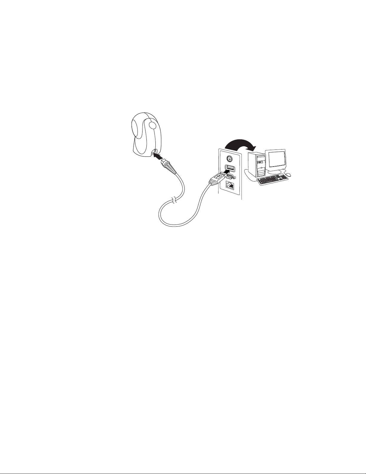
Connect with USB
The scanner can be connected to the USB port of a computer.
a. Connect the appropriate interface cable to the scanner first, then to the USB
port on the computer.
b. The scanner beeps.
c. Verify the scanner operation by scanning a bar code from the Sample
Symbols on page 231.
The unit defaults to a USB PC Keyboard. Refer to page 10 for other USB terminal
settings.
For additional USB programming and technical information, refer to “USB Application Note,” available at www.honeywellaidc.com.
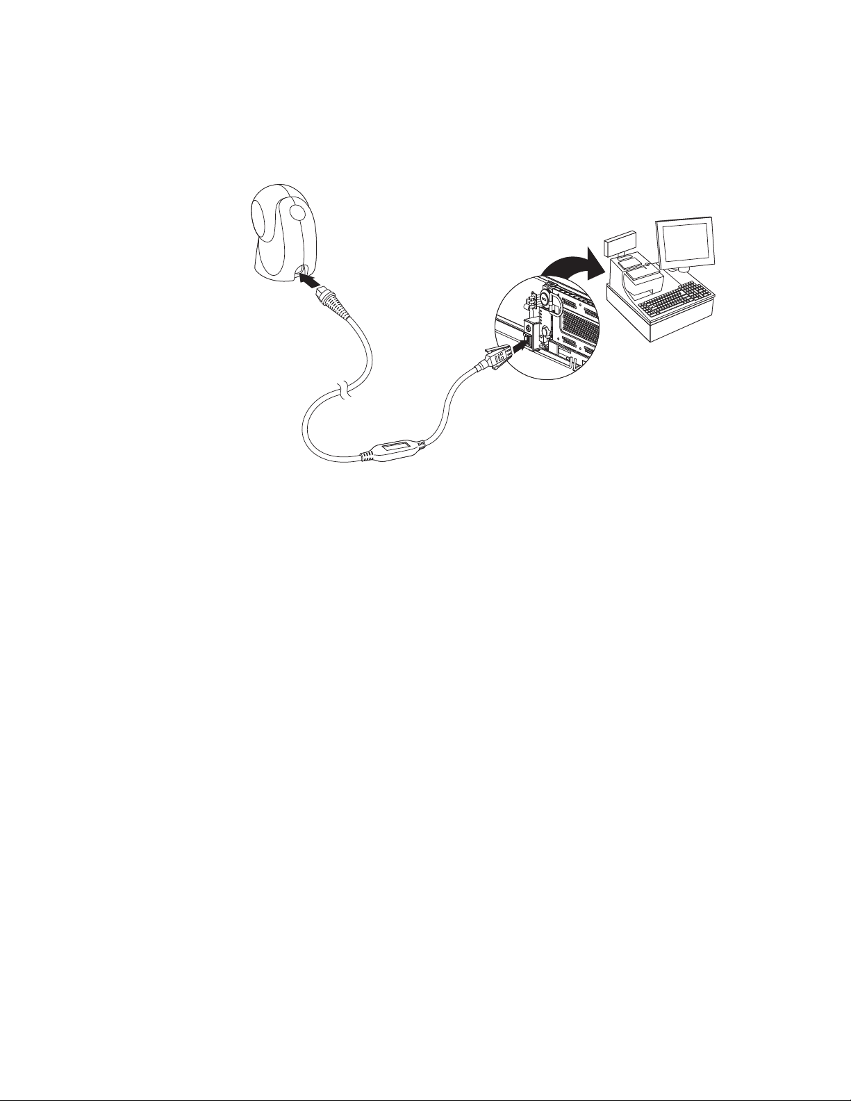
Connect with Keyboard Wedge
The scanner can be connected between the keyboard and PC as a “keyboard
wedge,” where the scanner provides data output that is similar to keyboard entries.
The following is an example of a keyboard wedge connection:
2 Orbit 7120plus/7190g User Guide
Page 17
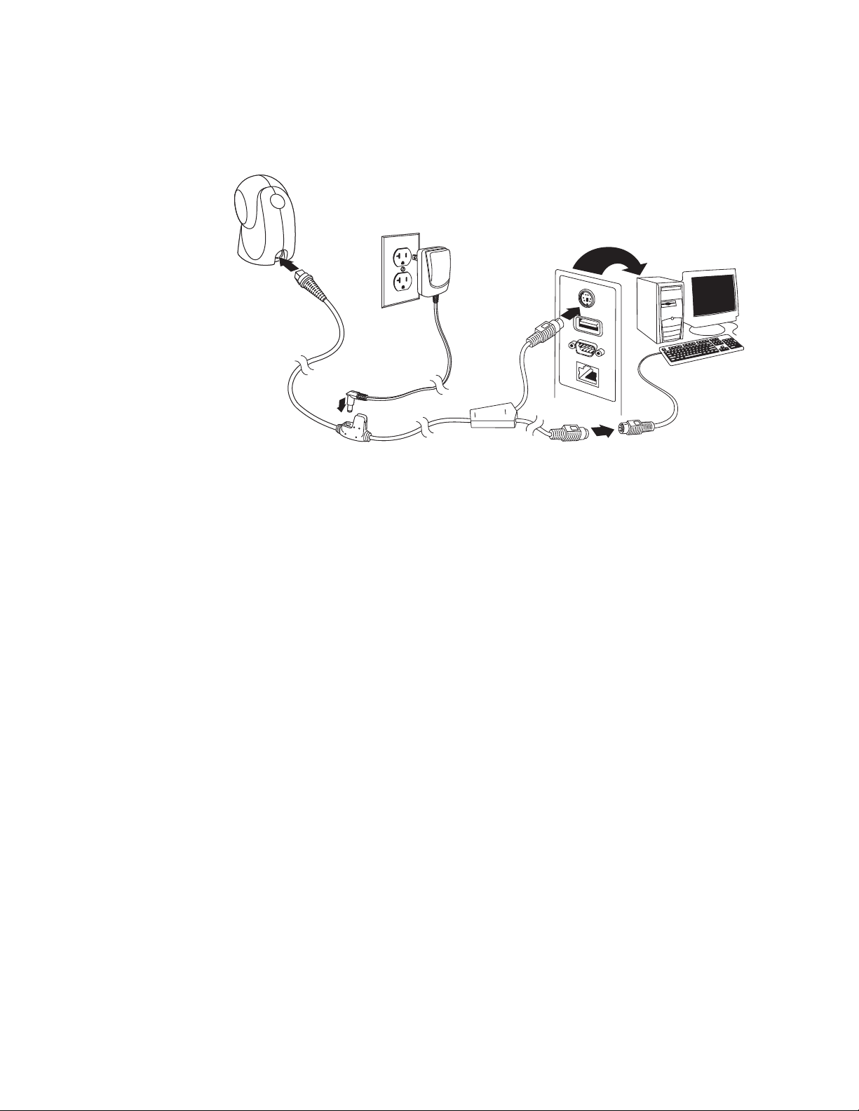
1. Turn off power and disconnect the keyboard cable from the back of the terminal/computer.
2. Connect the appropriate interface cable to the device and to the terminal/
computer.
Note: The power supply must be ordered separately, if needed.
3. Turn the terminal/computer power back on. The scanner beeps.
4. Verify the scanner operation by scanning a bar code from the Sample Symbols
on page 231. The scanner beeps once.
The unit defaults to an IBM PC AT and compatibles keyboard wedge interface with
a USA keyboard. A carriage return (CR) suffix is added to bar code data.
Orbit 7120plus/7190g User Guide 3
Page 18
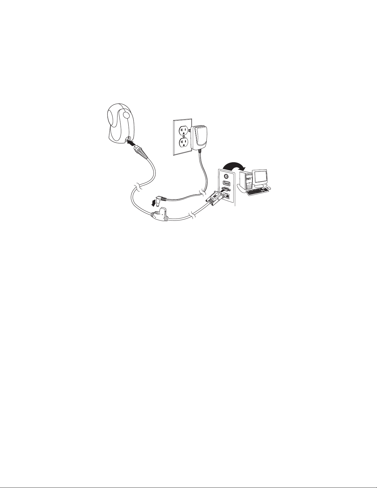
Connect with RS232 Serial Port
1. Turn off power to the terminal/computer.
2. Connect the appropriate interface cable to the scanner.
Note: For the scanner to work properly, you must have the correct cable for your type of
terminal/computer.
Note: For RS232, you must use the power supply.
3. Plug the serial connector into the serial port on your computer. Tighten the two
screws to secure the connector to the port.
4. Once the scanner has been fully connected, power up the computer.
This interface programs 115,200 baud, 8 data bits, no parity, and 1 stop bit.
4 Orbit 7120plus/7190g User Guide
Page 19
Connect with RS485
The scanner can be connected for an IBM POS terminal interface.
1. Connect the appropriate interface cable to the device, then to the computer.
2. Turn the terminal/computer power back on. The scanner beeps.
3. Verify the scanner operation by scanning a bar code from the Sample Symbols
on page 231. The scanner beeps once.
For further RS485 settings, refer to RS485,page 8.
Reading Techniques
Present the bar code to the scanner. When using an Orbit 7190g, the LEDs turn up
to read the code. If the light level in the room is not high enough, the code may not
be read.
Menu Bar Code Security Settings
Honeywell scanners are programmed by scanning menu bar codes or by sending
serial commands to the scanner. If you want to restrict the ability to scan menu
codes, you can use the Menu Bar Code Security settings. Contact the nearest technical support office (see Technical Assistance on page xi) for further information.
Orbit 7120plus/7190g User Guide 5
Page 20

Set Custom Defaults
Set Custom Defaults
Save Custom Defaults
Activate Custom Defaults
You have the ability to create a set of menu commands as your own, custom
defaults. To do so, scan the Set Custom Defaults bar code below before scanning
the menu commands for your custom defaults. If a menu command requires scanning numeric codes from the Programming Chart, beginning on page 233, then a
Save code, that entire sequence will be saved to your custom defaults. When you
have entered all the commands you want to save for your custom defaults, scan the
Save Custom Defaults bar code.
You may have a series of custom settings and want to correct a single setting. To do
so, just scan the new setting to overwrite the old one. For example, if you had previously saved the setting for Beeper Volume at Low to your custom defaults, and
decide you want the beeper volume set to High, just scan the Set Custom Defaults
bar code, then scan the Beeper Volume High menu code, and then Save Custom
Defaults. The rest of the custom defaults will remain, but the beeper volume setting will be updated.
Reset the Custom Defaults
If you want the custom default settings restored to your scanner, scan the Activate
Custom Defaults bar code below. This is the recommended default bar code for
most users. It resets the scanner to the custom default settings. If there are no custom defaults, it will reset the scanner to the factory default settings. Any settings
that have not been specified through the custom defaults will be defaulted to the
factory default settings.
6 Orbit 7120plus/7190g User Guide
Page 21

CHAPTER
2
PROGRAM THE INTERFACE
IBM PC AT and Compatibles with
CR suffix
Introduction
This chapter describes how to program your system for the desired interface.
Program the Interface - Plug and Play
Plug and Play bar codes provide instant scanner set up for commonly used interfaces.
Note: After you scan one of the codes, power cycle the host terminal to have the interface in
effect.
Keyboard Wedge
If you want your system programmed for an IBM PC AT and compatibles keyboard
wedge interface with a USA keyboard, scan the bar code below. Keyboard wedge is
the default interface.
Note: The following bar code also programs a carriage return (CR) suffix.
Orbit 7120plus/7190g User Guide 7
Page 22
Laptop Direct Connect
Laptop Direct Connect
with CR suffix
RS232 Interface
IBM Port 5B Interface
IBM Port 9B
HHBCR-1 Interface
For most laptops, scanning the Laptop Direct Connect bar code allows operation of
the scanner in parallel with the integral keyboard. The following Laptop Direct
Connect bar code also programs a carriage return (CR) suffix and turns on Emulate External Keyboard (page 24).ppp
RS232 Serial Port
The RS232 Interface bar code is used when connecting to the serial port of a PC or
terminal. The following RS232 Interface bar code also programs a carriage return
(CR) and a line feed (LF) suffix, baud rate, and data format as indicated below. It
also changes the trigger mode to presentation.
Option Setting
Baud Rate 115,200 bps
Data Format 8 data bits, no parity bit, 1 stop bit
RS485
Scan one of the following “Plug and Play” codes to program the scanner for an IBM
POS terminal interface.
Note: After scanning one of these codes, you must power cycle the cash register.
8 Orbit 7120plus/7190g User Guide
Page 23

Each bar code above also programs the following suffixes for each symbology:
IBM Port 17 Interface
IBM Port 9B
HHBCR-2 Interface
* Packet Mode Off
Packet Mode On
Packet Length
* Suffixes programmed for Code 128 with IBM 4683 Port 5B, IBM 4683 Port 9B HHBCR-1, and IBM 4683
Port 17 Interfaces
**Suffixes programmed for Code 128 with IBM 4683 Port 9 HHBCR-2 Interface
RS485 Packet Mode
The following selection allows you to break up large bar code data into smaller
packets on an IBM POS terminal. To break up large bar codes into small packets,
scan the Packet Mode On bar code below. Scan the Packet Mode Off bar code if
you want large bar code data to be sent to the host in a single chunk. Default =
Packet Mode Off.
Symbology Suffix Symbology Suffix
EAN 8 0C Code 39 00 0A 0B
EAN 13 16 Interleaved 2 of 5 00 0D 0B
UPC A 0D Code 128 * 00 0A 0B
UPC E 0A Code 128 ** 00 18 0B
MaxiCode 00 2F 0B
RS485 Packet Length
If you are using Packet mode, you can specify the size of the data “packet” that is
sent to the host. Scan the Packet Length bar code, then the packet size (from 20 -
256) from the Programming Chart, beginning on page 233 of this manual, then
Save. Default = 40.
Orbit 7120plus/7190g User Guide 9
Page 24
USB IBM SurePos
USB IBM SurePos
(USB Handheld Scanner)
Interface
USB IBM SurePos
(USB Tabletop Scanner)
Interface
U
S
B
K
e
y
b
o
a
r
d
(
P
C
)
USB Keyboard (Mac)
USB Japanese Keyboard (PC)
Scan one of the following “Plug and Play” codes to program the scanner for an IBM
SurePos (USB handheld scanner) or IBM SurePos (USB tabletop scanner) interface.
Note: After scanning one of these codes, you must power cycle the cash register.
Each bar code above also programs the following suffixes for each symbology:
Symbology Suffix Symbology Suffix
EAN 8 0C Code 39 00 0A 0B
EAN 13 16 Interleaved 2 of 5 00 0D 0B
UPC A 0D Code 128 00 18 0B
UPC E 0A Code 39 00 0A 0B
USB PC or Macintosh Keyboard
Scan one of the following codes to program the scanner for USB PC Keyboard or
USB Macintosh Keyboard. Scanning these codes also adds a CR suffix.
10 Orbit 7120plus/7190g User Guide
Page 25
USB HID
USB HID Bar Code Scanner
USB Serial
CTS/RTS Emulation On
* CTS/RTS Emulation Off
ACK/NAK Mode On
USB Serial
Scan the following code to program the scanner for USB HID bar code scanners.
Scan the following code to program the scanner to emulate a regular RS232-based
COM Port. If you are using a Microsoft® Windows® PC, you will need to download a
driver from the Honeywell website (www.honeywellaidc.com) and go to Get
Resources - Downloads - Software. The driver will use the next available COM
Port number. Apple® Macintosh computers recognize the scanner as a USB CDC
class device and automatically use a class driver.
Note: No extra configuration (e.g., baud rate) is necessary.
CTS/RTS Emulation
ACK/NAK Mode
Orbit 7120plus/7190g User Guide 11
Page 26

Remote MasterMind™ for USB
* ACK/NAK Mode Off
ReM Off
* ReM On
Verifone Ruby Settings
When using a USB interface, you may wish to configure your scanner to communicate with Remote MasterMind Scanner Management Software (ReM). Scan the
ReM On bar code to communicate with ReM. To disable this capability, scan ReM
Off. Default = ReM On.
Verifone® Ruby Terminal
Scan the following Plug and Play code to program the scanner for a Verifone Ruby
terminal. This bar code sets the baud rate to 1200 bps and the data format to 8
data bits, mark parity bit, 1 stop bit. It also adds a line feed (LF) suffix and programs the following prefixes for each symbology:
Symbology Prefix
UPC-A A
UPC-E A
EAN-8 FF
EAN-13 F
12 Orbit 7120plus/7190g User Guide
Page 27

Gilbarco® Terminal
Gilbarco Settings
Honeywell Bioptic Settings
Datalogic Magellan Settings
Scan the following Plug and Play code to program the scanner for a Gilbarco terminal. This bar code sets the baud rate to 2400 bps and the data format to 7 data bits,
even parity, 2 stop bits. It also adds a carriage return (CR) suffix and programs the
following prefixes for each symbology:
Symbology Prefix
UPC-A A
UPC-E E0
EAN-8 FF
EAN-13 F
Honeywell Bioptic Aux Port
Scan the following Plug and Play code to program the scanner for a Honeywell
bioptic scanner auxiliary port configuration. This bar code sets the baud rate to
38400 bps and the data format to 8 data bits, no parity, 1 stop bit.
Datalogic™ Magellan® Aux Port
Scan the following Plug and Play code to program the scanner for a Datalogic
Magellan auxiliary port configuration. This bar code sets the baud rate to 9600 bps
and the data format to 8 data bits, no parity, 1 stop bit.
Orbit 7120plus/7190g User Guide 13
Page 28
NCR Bioptic Aux Port
NCR Bioptic Settings
Wincor Nixdorf Terminal Settings
Scan the following Plug and Play code to program the scanner for an NCR bioptic
scanner auxiliary port configuration. The following prefixes are programmed for
each symbology:
Symbology Prefix Symbology Prefix
UPC-A A Interleaved 2 of 5 b
UPC-E E0 Code 128 f
EAN-8 FF Code 39 a
EAN-13 F
Wincor Nixdorf Terminal
Scan the following Plug and Play code to program the scanner for a Wincor Nixdorf
terminal. This bar code sets the baud rate to 9600 bps and the data format to 8
data bits, no parity, 1 stop bit.
Code 32
Pharmaceutical
(PARAF)
a
Wincor Nixdorf Beetle™ Terminal
Scan the following Plug and Play code to program the scanner for a Wincor Nixdorf
Beetle terminal. The following prefixes are programmed for each symbology:
Symbology Prefix Symbology Prefix
Aztec Code V Interleaved 2 of 5 I
Codabar N MaxiCode T
Code 93 L MicroPDF417 S
Code 128 K PDF417 Q
Data Matrix R QR Code U
EAN-8 B Straight 2 of 5 IATA H
EAN-13 A UPC-A A0
GS1 DataBar E UPC-E C
GS1-128 P All other bar codes M
14 Orbit 7120plus/7190g User Guide
Page 29
Wincor Nixdorf RS232 Mode A
Wincor Nixdorf Beetle Settings
Wincor Nixdorf RS232 Mode A
Settings
* United States
Albania
Scan the following Plug and Play code to program the scanner for a Wincor Nixdorf
RS232 Mode A terminal. This bar code sets the baud rate to 9600 bps and the data
format to 8 data bits, odd parity, 1 stop bit. The following prefixes are programmed
for each symbology:
Symbology Prefix Symbology Prefix
Code 128 K EAN-13 A
Code 93 L GS1-128 K
Codabar N Interleaved 2 of 5 I
UPC-A A0 Plessey O
UPC-E C Straight 2 of 5 IATA H
EAN-8 B GS1 DataBar E
All other bar codes M
Keyboard Country Layout
If your interface is USB Keyboard or Keyboard Wedge, your keyboard layout default
is a US keyboard. To change this layout, scan the appropriate Keyboard Country
bar code below. By default, national character replacements are used for the following characters: # $ @ [ \ ] ^ ‘ { | } ~. Refer to the ISO 2022/ISO 646
Character Replacements on page 226 to view the character replacements for each
country.
Keyboard Countries
Orbit 7120plus/7190g User Guide 15
Page 30
Keyboard Countries (Continued)
Azeri (Cyrillic)
Azeri (Latin)
Belarus
Belgium
Bosnia
Brazil
Brazil (MS)
Bulgaria (Cyrillic)
Bulgaria (Latin)
Canada (French legacy)
Canada (French)
16 Orbit 7120plus/7190g User Guide
Page 31

Keyboard Countries (Continued)
Canada (Multilingual)
Croatia
Czech
Czech (Programmers)
Czech (QWERTY)
Czech (QWERTZ)
Denmark
Dutch (Netherlands)
Estonia
Faroese
Finland
Orbit 7120plus/7190g User Guide 17
Page 32

Keyboard Countries (Continued)
France
Gaelic
Germany
Greek
Greek (220 Latin)
Greek (220)
Greek (319 Latin)
Greek (319)
Greek (Latin)
Greek (MS)
Greek (Polytonic)
18 Orbit 7120plus/7190g User Guide
Page 33

Keyboard Countries (Continued)
Hebrew
Hungarian (101 key)
Hungary
Iceland
Irish
Italian (142)
Italy
Japan ASCII
Kazakh
Kyrgyz (Cyrillic)
Latin America
Orbit 7120plus/7190g User Guide 19
Page 34

Keyboard Countries (Continued)
Latvia
Latvia (QWERTY)
Lithuania
Lithuania (IBM)
Macedonia
Malta
Mongolian (Cyrillic)
Norway
Poland
Polish (214)
Polish (Programmers)
Portugal
20 Orbit 7120plus/7190g User Guide
Page 35

Keyboard Countries (Continued)
Romania
Russia
Russian (MS)
Russian (Typewriter)
SCS
Serbia (Cyrillic)
Serbia (Latin)
Slovakia
Slovakia (QWERTY)
Slovakia (QWERTZ)
Slovenia
Spain
Orbit 7120plus/7190g User Guide 21
Page 36

Keyboard Countries (Continued)
Spanish variation
Sweden
Switzerland (French)
Switzerland (German)
Tatar
Turkey F
Turkey Q
Ukrainian
United Kingdom
United States (Dvorak)
United States (Dvorak left)
United Stated (Dvorak
22 Orbit 7120plus/7190g User Guide
Page 37

Keyboard Countries (Continued)
United States (International)
Uzbek (Cyrillic)
* Off
4 Characters
* Regular
Keyboard Wedge Modifiers
ALT Mode
If your bar code contains special characters from the extended ASCII chart, for
example, an e with an accent grave (è), you will use ALT Mode. (See "Extended
ASCII Characters" on page 223.)
Note: Scan the ALT mode bar code after scanning the appropriate Keyboard Country code.
If your keystrokes require the ALT key and 4 characters, scan the 4 Characters bar
code. The data is then output with the special character(s). Default = Off.
Keyboard Style
Orbit 7120plus/7190g User Guide 23
This programs keyboard styles, such as Caps Lock and Shift Lock. If you have used
Keyboard Conversion settings, they will override any of the following Keyboard
Style settings. Default = Regular.
Regular is used when you normally have the Caps Lock key off.
Page 38

Caps Lock is used when you normally have the Caps Lock key on.
Caps Lock
Shift Lock
Automatic Caps Lock
Autocaps via NumLock
Emulate External Keyboard
Shift Lock is used when you normally have the Shift Lock key on (not common to
U.S. keyboards).
Automatic Caps Lock is used if you change the Caps Lock key on and off. The software tracks and reflects if you have Caps Lock on or off . This selection can only be
used with systems that have an LED that notes the Caps Lock status (AT keyboards).
The Autocaps via NumLock bar code should be scanned in countries (e.g., Germany, France) where the Caps Lock key cannot be used to toggle Caps Lock. The
NumLock option works similarly to the regular Autocaps, but uses the NumLock
key to retrieve the current state of the Caps Lock.
Emulate External Keyboard should be scanned if you do not have an external keyboard (IBM AT or equivalent).
Note: After scanning the Emulate External Keyboard bar code, you must power cycle your
computer.
Keyboard Conversion
Alphabetic keyboard characters can be forced to be all upper case or all lowercase.
So if you have the following bar code: “abc569GK,” you can make the output
“ABC569GK” by scanning Convert All Characters to Upper Case, or to “abc569gk”
by scanning Convert All Characters to Lower Case.
24 Orbit 7120plus/7190g User Guide
Page 39

These settings override Keyboard Style selections.
* Keyboard Conversion Off
Convert All Characters
to Upper Case
Convert All Characters
to Lower Case
Control Character Output On
* Control Character Output Off
Note: If your interface is a keyboard wedge, first scan the menu code for Automatic Caps
Lock (page 24). Otherwise, your output may not be as expected.
Default = Keyboard Conversion Off.
Control Character Output
This selection sends a text string instead of a control character. For example, when
the control character for a carriage return is expected, the output would display
[CR] instead of the ASCII code of 0D. Refer to ASCII Conversion Chart (Code Page
1252) on page 222. Only codes 00 through 1F are converted (the first column of
the chart). Default = Off.
Note: Control + X (Control + ASCII) Mode overrides this mode.
Keyboard Modifiers
This modifies special keyboard features, such as CTRL+ ASCII codes and Turbo
Mode.
Orbit 7120plus/7190g User Guide 25
Page 40

Control + X (Control + ASCII) Mode On: The scanner sends key combinations for
Windows Mode Control + X
Mode On
* Control + X Mode Off
DOS Mode Control + X Mode On
Windows Mode Prefix/Suffix
Turbo Mode On
* Turbo Mode Off
Numeric Keypad Mode On
ASCII control characters for values 00-1F. Windows is the preferred mode. All keyboard country codes are supported. DOS mode is a legacy mode, and it does not
support all keyboard country codes. New users should use the Windows mode.
Refer to ASCII Conversion Chart (Code Page 1252), page 222 for CTRL+ X Values.
Windows Mode Prefix/Suffix Off: The scanner sends key combinations for ASCII
control characters for values 00-1F, but it does not translate prefix or suffix information.
Default = Control + X Mode Off.
Turbo Mode: The scanner sends characters to a terminal faster. If the terminal
drops characters, do not use Turbo Mode. Default = Off.
Numeric Keypad Mode: Sends numeric characters as if entered from a numeric
keypad. Default = Off.
26 Orbit 7120plus/7190g User Guide
Page 41

Automatic Direct Connect Mode: This selection can be used if you have an IBM
* Numeric Keypad Mode Off
Automatic Direct Connect
Mode On
* Automatic Direct Connect
Mode Off
300
600
1200
2400
4800
AT style terminal and the system is dropping characters. Default = Off.
RS232 Modifiers
RS232 Baud Rate
Baud Rate sends the data from the scanner to the terminal at the specified rate.
The host terminal must be set for the same baud rate as the scanner. Default =
115,200.
Orbit 7120plus/7190g User Guide 27
Page 42

RS232 Word Length: Data Bits, Stop Bits, and Parity
9600
19200
38400
57,600
* 115,200
7 Data, 1 Stop, Parity Even
7 Data, 1 Stop, Parity None
7 Data, 1 Stop, Parity Odd
7 Data, 2 Stop, Parity Even
Data Bits sets the word length at 7 or 8 bits of data per character. If an application
requires only ASCII Hex characters 0 through 7F decimal (text, digits, and punctuation), select 7 data bits. For applications that require use of the full ASCII set, select
8 data bits per character. Default = 8.
Stop Bits sets the stop bits at 1 or 2. Default = 1.
Parity provides a means of checking character bit patterns for validity. Default =
None.
28 Orbit 7120plus/7190g User Guide
Page 43

RS232 Receiver Time-Out
7 Data, 2 Stop Parity None
7 Data, 2 Stop, Parity Odd
8 Data, 1 Stop, Parity Even
* 8 Data, 1 Stop, Parity None
8 Data, 1 Stop, Parity Odd
8 Data, 1 Stop, Parity Mark
RS232 Receiver Time-Out
The unit stays awake to receive data until the RS232 Receiver Time-Out expires. A
manual or serial trigger resets the time-out. When an RS232 receiver is sleeping, a
character may be sent to wake up the receiver and reset the time-out. A transaction
on the CTS line will also wake up the receiver. The receiver takes 300 milliseconds
to completely come up. Change the RS232 receiver time-out by scanning the bar
code below, then scanning digits from the inside back cover of this manual, then
scanning Save. The range is 0 to 300 seconds. Default = 0 seconds (no time-out -
always on).
RS232 Handshaking
RS232 Handshaking allows control of data transmission from the scanner using
software commands from the host device. When RTS/CTS is turned Off, no data
flow control is used.
Flow Control, No Timeout: The scanner asserts RTS when it has data to send, and
will wait indefinitely for CTS to be asserted by the host.
Orbit 7120plus/7190g User Guide 29
Page 44

Two-Direction Flow Control: The scanner asserts RTS when it is OK for the host to
Flow Control, No Timeout
Two-Direction Flow Control
Flow Control with Timeout
* RTS/CTS Off
RS232 Timeout
XON/XOFF On
transmit. The host asserts CTS when it is OK for the device to transmit.
Flow Control with Timeout: The scanner asserts RTS when it has data to send and
waits for a delay (see RS232 Timeout on page 30) for CTS to be asserted by the
host. If the delay time expires and CTS is not asserted, the device transmit buffer is
cleared and scanning may resume. Default = RTS/CTS Off.
RS232 Timeout
When using Flow Control with Timeout, you must program the length of the delay
you want to wait for CTS from the host. Set the length (in milliseconds) for a timeout by scanning the bar code below, then setting the timeout (from 1-5100 milliseconds) by scanning digits from the inside back cover, then scanning Save.
XON/XOFF
Standard ASCII control characters can be used to tell the scanner to start sending
data (XON/XOFF On) or to stop sending data (XON/XOFF Off). When the host
sends the XOFF character (DC3, hex 13) to the scanner, data transmission stops.
To resume transmission, the host sends the XON character (DC1, hex 11). Data
transmission continues where it left off when XOFF was sent. Default = XON/XOFF
Off.
30 Orbit 7120plus/7190g User Guide
Page 45

ACK/NAK
* XON/XOFF Off
ACK/NAK On
* ACK/NAK Off
* Packet Mode Off
Packet Mode On
After transmitting data, the scanner waits for an ACK character (hex 06) or a NAK
character (hex 15) response from the host. If ACK is received, the communications
cycle is completed and the scanner looks for more bar codes. If NAK is received, the
last set of bar code data is retransmitted and the scanner waits for ACK/NAK again.
Turn on the ACK/NAK protocol by scanning the ACK/NAK On bar code below. To
turn off the protocol, scan ACK/NAK Off. Default = ACK/NAK Off.
Scanner to Bioptic Communication
The following settings are used to set up communication between Honeywell scanners and bioptic scanners.
Note: The scanner’s baud rate must be set to 38400 and the RS232 timeout must be set to
3000 in order to communicate with a bioptic scanner. See RS232 Modifiers on page
27, and RS232 Timeout on page 30 for further information.
Scanner-Bioptic Packet Mode
Packet Mode On must be scanned to set the scanner’s format so it is compatible
with a bioptic scanner. Default = Packet Mode Off.
Orbit 7120plus/7190g User Guide 31
Page 46

Scanner-Bioptic ACK/NAK Mode
* Bioptic ACK/NAK Off
Bioptic ACK/NAK On
ACK/NAK Timeout
Bioptic ACK/NAK On must be scanned so the scanner will wait for an ACK or NAK
from a bioptic scanner after each packet is sent. The Scanner-Bioptic ACK/NAK
Timeout (below) controls how long the scanner will wait for a response. Default =
Bioptic ACK/NAK Off.
Scanner-Bioptic ACK/NAK Timeout
This allows you to set the length (in milliseconds) for a timeout for a bioptic scanner’s ACK/NAK response. Scan the bar code below, then set the timeout (from 130,000 milliseconds) by scanning digits from the inside back cover, then scanning
Save. Default = 5100.
32 Orbit 7120plus/7190g User Guide
Page 47

CHAPTER
3
INPUT/OUTPUT SETTINGS
Power Up Beeper Off -
Scanner
* Power Up Beeper On -
Scanner
Power Up Beeper Off -
Cordless Base
Power Up Beeper On -
Cordless Base
Power Up Beeper
The scanner can be programmed to beep when it’s powered up. Scan the Off bar
code(s) if you don’t want a power up beep. Default = Power Up Beeper On - Scanner.
Good Read and Error Indicators
Beeper – Good Read
The beeper may be programmed On or Off in response to a good read. Turning this
option off only turns off the beeper response to a good read indication. All error and
menu beeps are still audible. Default = Beeper - Good Read On.
Orbit 7120plus/7190g User Guide 33
Page 48

Beeper Volume – Good Read
Beeper - Good Read Off
* Beeper - Good Read On
Low
Medium
* High
Off
Low (1600 Hz)
* Medium (2591 Hz)
High (4200 Hz)
The beeper volume codes modify the volume of the beep the scanner emits on a
good read. Default = High.
Beeper Pitch – Good Read
34 Orbit 7120plus/7190g User Guide
The beeper pitch codes modify the pitch (frequency) of the beep the scanner emits
on a good read. Default = Medium.
Page 49

Beeper Pitch – Error
* Razz (250 Hz)
Medium (3250 Hz)
High (4200 Hz)
* Normal Beep
Short BeepShort Beep
* LED - Good Read On
LED - Good Read Off
The beeper pitch codes modify the pitch (frequency) of the sound the scanner
emits when there is a bad read or error. Default = Razz.
Beeper Duration – Good Read
The beeper duration codes modify the length of the beep the scanner emits on a
good read. Default = Normal.
LED – Good Read
The LED indicator can be programmed On or Off in response to a good read.
Default = On.
Orbit 7120plus/7190g User Guide 35
Page 50

Number of Beeps – Good Read
Number of Good Read Beeps/LED Flashes
Number of Error Beeps/LED Flashes
* No Delay
Short Delay (500 ms)
Medium Delay (1,000 ms)
Long Delay (1,500 ms)
The number of beeps of a good read can be programmed from 1 - 9. The same
number of beeps will be applied to the beeper and LED in response to a good read.
For example, if you program this option to have five beeps, there will be five beeps
and five LED flashes in response to a good read. The beeps and LED flashes are in
sync with one another. To change the number of beeps, scan the bar code below
and then scan a digit (1-9) bar code and the Save bar code from the Programming
Chart, beginning on page 233. Default = 1.
Number of Beeps – Error
The number of beeps and LED flashes emitted by the scanner for a bad read or
error can be programmed from 1 - 9. For example, if you program this option to
have five error beeps, there will be five error beeps and five LED flashes in response
to an error. To change the number of error beeps, scan the bar code below and then
scan a digit (1-9) bar code and the Save bar code from the Programming Chart,
beginning on page 233. Default = 1.
Good Read Delay
This sets the minimum amount of time before the scanner can read another bar
code. Default = 0 ms (No Delay).
36 Orbit 7120plus/7190g User Guide
Page 51

User-Specified Good Read Delay
User-Specified Good Read Delay
Read Time-Out
Presentation Mode
If you want to set your own length for the good read delay, scan the bar code below,
then set the delay (from 0 - 30,000 milliseconds) by scanning digits from the inside
back cover, then scanning Save.
Serial Trigger Mode
You can activate the scanner by using a serial trigger command (see Trigger
Commands on page 186). When in serial mode, the scanner scans until a bar code
has been read or until the deactivate command is sent. The scanner can also be set
to turn itself off after a specified time has elapsed (see Read Time-Out, which follows).
Read Time-Out
Use this selection to set a time-out (in milliseconds) of the scanner’s trigger when
using serial commands to trigger the scanner. Once the scanner has timed out, you
can activate the scanner by using a serial trigger command. After scanning the
Read Time-Out bar code, set the time-out duration (from 0-300,000 milliseconds)
by scanning digits from the Programming Chart, beginning on page 233, then
scanning Save. Default = 30,000 ms.
Presentation Mode
Note: Presentation Mode is not supported by the Orbit 7120plus scanner.
Orbit 7120plus/7190g User Guide 37
Presentation Mode uses laser or scanner illumination to detect bar codes. When in
Presentation Mode, the LEDs remain dim until a bar code is presented to the scanner, then the LEDs turn up to read the code. If the light level in the room is not high
enough, Presentation Mode may not work properly.
Scan the following bar code to program your scanner for Presentation Mode.
Page 52

Presentation Idle Mode
Presentation Idle Mode
Off
LEDs On
* LEDs Off
When Presentation Idle Mode is selected, when there is no activity, the scanner
illumination turns off for a length of time. After scanning the Presentation Idle
Mode bar code, set the idle time duration (from 0-300,000 milliseconds) by scanning digits from the Programming Chart, beginning on page 233, then scanning
Save. Default = 500 (0.5 seconds).
When Off is selected, the scanner remains powered on.
Note: This selection is unavailable when the Illumination Lights are set to off.
Presentation LED Behavior after Decode
Note: This feature is not supported by the Orbit 7120plus scanner.
If you wish to turn off the LEDs immediately after a bar code is decoded, scan the
LEDs Off bar code, below. Default = LEDs Off.
Presentation Sensitivity
Note: This feature is not supported by the Orbit 7120plus scanner.
38 Orbit 7120plus/7190g User Guide
Page 53

Presentation Sensitivity is a numeric range that increases or decreases the scan-
Sensitivity
ner's reaction time to bar code presentation. To set the sensitivity, scan the Sensitivity bar code, then scan the degree of sensitivity (from 0-20) from the
Programming Chart, beginning on page 233, and Save. 0 is the most sensitive set-
ting, and 20 is the least sensitive. Default = 5.
Presentation Centering
Use Presentation Centering to narrow the imager’s field of view to make sure the
scanner reads only those bar codes intended by the user. For instance, if multiple
codes are placed closely together, Presentation Centering will insure that only the
desired codes are read.
If a bar code is not touched by a predefined window, it will not be decoded or output
by the scanner. If Presentation Centering is turned on by scanning Presentation
Centering On, the imager only reads codes that pass through the centering window you specify using the Top of Presentation Centering Window, Bottom of
Presentation Centering Window, Left, and Right of Presentation Centering Window bar codes.
Example: In the example below, the white box is the centering window. The centering window
has been set to 20% left, 30% right, 8% top, and 25% bottom. Since Bar Code 1
passes through the centering window, it will be read. Bar Code 2 does not pass
through the centering window, so it will not be read.
Orbit 7120plus/7190g User Guide 39
Page 54

Note: A bar code needs only to be touched by the centering window in order to be read. It
0
Bar Code 1
Bar Code 2
10 20 30 40 50 60 70 80 90 100%
100
90
80
70
60
50
40
30
20
10
0%
Presentation Centering On
* Presentation Centering Off
Top of Presentation
Centering Window
Bottom of Presentation
Centering Window
does not need to pass completely through the centering window.
Scan Presentation Centering On, then scan one of the following bar codes to
change the top, bottom, left, or right of the centering window. Then scan the percent you want to shift the centering window using digits from the Programming
Chart, beginning on page 233, then scan Save. Default Presentation Centering =
40% for Top and Left, 60% for Bottom and Right.
40 Orbit 7120plus/7190g User Guide
Page 55

Poor Quality Codes
Left of
Presentation Centering
Window
Right of Presentation
Centering Window
Poor Quality 1D Reading On
* Poor Quality 1D Reading Off
Poor Quality PDF Reading On
Poor Quality 1D Codes
This setting improves the scanner’s ability to read damaged or badly printed linear
bar codes. When Poor Quality 1D Reading On is scanned, poor quality linear bar
code reading is improved, but the scanner’s snappiness is decreased, making it
less aggressive when reading good quality bar codes. This setting does not affect
2D bar code reading. Default = Poor Quality 1D Reading Off.
Poor Quality PDF Codes
Orbit 7120plus/7190g User Guide 41
This setting improves the scanner’s ability to read damaged or badly printed PDF
codes by combining information from multiple images. When Poor Quality PDF
On is scanned, poor quality PDF code reading is improved, but the scanner’s snappiness is decreased, making it less aggressive when reading good quality bar
codes. This setting does not affect 1D bar code reading. Default = Poor Quality PDF
Reading Off.
Page 56

Mobile Phone Read Mode
* Poor Quality PDF Reading
Off
Presentation Scanning -
Mobile Phone
* Short (500 ms)
* Medium (750 ms)
Long (1000 ms)
Extra Long (2000 ms)
Note: This feature is the default for the Orbit 7120plus scanner and cannot be changed. It
is only configurable for the Orbit 7190g scanner.
When this mode is selected, your scanner is optimized to read bar codes from a
mobile phone or other LED displays. However, the speed of scanning printed bar
codes may be slightly lower when this mode is enabled.
Reread Delay
This sets the time period before the scanner can read the same 1D bar code a second time. Setting a reread delay protects against accidental rereads of the same
1D bar code. Longer delays are effective in minimizing accidental rereads. Use
shorter delays in applications where repetitive 1D bar code scanning is required.
Reread Delay only works when in a Presentation Mode (see page 37). Default =
Short.
42 Orbit 7120plus/7190g User Guide
Page 57

User-Specified Reread Delay
User-Specified Reread Delay
Short (500 ms)
* Medium (750ms)
Long (1000ms)
Extra Long (2000ms)
2D Reread Delay Off
If you want to set your own length for the reread delay, scan the bar code below,
then set the delay (from 0-30,000 milliseconds) by scanning digits from the
Programming Chart, beginning on page 233, then scanning Save.
2D Reread Delay
Sometimes 2D bar codes can take longer to read than other bar codes. If you wish
to set a separate Reread Delay for 2D bar codes, scan one of the programming
codes that follows. 2D Reread Delay Off indicates that the time set for Reread
Delay is used for both 1D and 2D bar codes. Default = 2D Reread Delay Off.
Illumination Lights
Note: This feature is not supported by the Orbit 7120plus scanner.
Orbit 7120plus/7190g User Guide 43
If you want the illumination lights on while reading a bar code, scan the Lights On
bar code, below. However, if you want to turn just the lights off, scan the Lights Off
bar code. Default = Lights On.
Page 58

Host Acknowledgment
* Lights On
Lights Off
Some applications require that the host terminal (or server) validate incoming bar
code data (database look-up) and provide acknowledgment to the scanner
whether or not to proceed. In Host ACK Mode, the scanner waits for this acknowledgment after each scan. Visual and audible acknowledgments provide valuable
feedback to the scan operator. The Host ACK functionality is controlled via a number of pre-defined escape commands that are sent to the scanner to make it
behave in different ways.
Note: System performance degrades when using Host ACK at rates lower than 9600 baud.
The following criteria must be met for the Host ACK to work correctly:
• The scanner must be configured for Host Port RS232 (terminal ID = 000) or USB
COM Emulation (terminal ID = 130).
• RTS/CTS is defaulted off. You must enable it if the host system requires it.
• Host ACK must be set to On (page 45).
• A comma must be used as a terminator.
• The host terminal software must be capable of interpreting the bar code data,
make decisions based on the data content, and send out appropriate escape
commands to the scanner.
The commands to which the scanner responds are listed on page 45. The [ESC] is a
1B in hex. A typical command string is [ESC] x, where “[ESC] x” is the escape command and the comma is the terminator, which is required.
Example: Commands may be strung together to create custom response sequences. An
example of a command string is listed below.
• [ESC]4,[ESC]5,[ESC]6,
The above example will make a scanner zero beep low, then medium, then high.
Example: A good read beep is required for any item on file, but a razz or error tone is required
if the item is not on file. In this case,
• [ESC]7, is sent from the host to the scanner for an on-file product
• [ESC]8,[ESC]8, is sent from the host to the scanner for a not-on-file product
44 Orbit 7120plus/7190g User Guide
Page 59

When a bar code is scanned, the scanner enters a timeout period until either the
Host ACK On
* Host ACK Off
Host ACK Timeout
host ACK sequence is received, or the timeout expires (in 10 seconds, by default).
Once Host ACK is enabled, the system works as follows when a bar code is
scanned:
• The scanner reads the code and sends data to the host system. No audible or
visual indication is emitted until the scanner receives an escape command. The
scanner read illumination goes out when there’s a successful read.
• Scanner operation is suspended until 1) a valid escape string is received from
the host system or 2) the scanner times out.
• Once condition 1 or 2 above has been met, the scanner is ready to scan again,
and the process repeats.
A time-out occurs if the scanner does not receive a valid escape command within
10 seconds. A time-out is indicated by an error tone. If a time-out occurs, the operator should check the host system to understand why a response to the scanner
was not received.
Host ACK On/Off
Host ACK Timeout
You can set a timeout for the length of time the scanner waits for a valid escape
command when using Host Acknowledgment Mode. Set the length (in seconds) for
a timeout by scanning the following bar code, then setting the timeout (from 1-90
seconds) by scanning digits from the Programming Chart, beginning on page 233,
then scanning Save. Default = 10.
Host ACK Responses
Command Action
[ESC] a, Double beeps to indicate a successful menu change was made.
Orbit 7120plus/7190g User Guide 45
Page 60

Command Action
* Off
On
[ESC] b, Razz or error tone to indicate a menu change was unsuccessful.
[ESC] 1, The white LED illuminates for 135 milliseconds followed by a pause.
[ESC] 2, The white LED illuminates for 2 seconds followed by a pause.
[ESC] 3, The white LED illuminates for 5 seconds followed by a pause.
[ESC] 4, Emits a beep at a low pitch.
[ESC] 5, Emits a beep at a medium pitch.
[ESC] 6, Emits a beep at a high pitch.
[ESC] 7, Beeps to indicate a successful decode and communication to host.
[ESC] 8,[ESC] 8, Razz or error tone to indicate a decode/communication to host was
unsuccessful.
Character Activation Mode
Y2ou may use a character sent from the host to trigger the scanner to begin scanning. When the activation character is received, the scanner continues scanning
until either the Character Activation Timeout (page 47), the deactivation character
is received (see Deactivation Character on page 48), or a bar code is transmitted.
Scan the following On bar code to use character activation, then use Activation
Character (following) to select the character you will send from the host to start
scanning. Default = Off.
Activation Character
This sets the character used to trigger scanning when using Character Activation
Mode. On the ASCII Conversion Chart (Code Page 1252), page 222, find the hex
value that represents the character you want to use to trigger scanning. Scan the
46 Orbit 7120plus/7190g User Guide
Page 61

following bar code, then scan the alphanumeric combination that represents that
Activation Character
Do Not End Character
Activation After Good Read
* End Character Activation
After Good Read
Character Activation Timeout
ASCII character from the Programming Chart, beginning on page 233, then scan
Save. Default = 12 [DC2].
End Character Activation After Good Read
After a bar code is successfully detected and read from the scanner, the illumination can be programmed either to remain on and scanning, or to turn off. When
End Character Activation After Good Read is enabled, the illumination turns off
and stops scanning after a good read. If you scan Do Not End Character Activa-
tion After Good Read, the illumination remains on after a good read. Default = End
Character Activation After Good Read.
Character Activation Timeout
You can set a timeout for the length of time the illumination remains on and
attempting to decode bar codes when using Character Activation Mode. Set the
length (in milliseconds) for a timeout by scanning the following bar code, then setting the timeout (from 1-300,000 milliseconds) by scanning digits from the
Programming Chart, beginning on page 233, then scanning Save. Default = 30,000
ms.
Orbit 7120plus/7190g User Guide 47
Page 62

Character Deactivation Mode
* Off
On
Deactivation Character
*D/E Character Off
D/E Character On
If you have sent a character from the host to trigger the scanner to begin scanning,
you can also send a deactivation character to stop scanning. Scan the following On
bar code to use character deactivation, then use Deactivation Character (following)
to select the character you will send from the host to terminate scanning. Default =
Off.
Deactivation Character
This sets the character used to terminate scanning when using Character Deactivation Mode. On the ASCII Conversion Chart (Code Page 1252), page 222, find the
hex value that represents the character you want to use to terminate scanning.
Scan the following bar code, then scan the alphanumeric combination that represents that ASCII character from the Programming Chart, beginning on page 233.
Scan Save to finish. Default = 14 [DC4].
D/E Character (Disable/Enable)
If you want to enable scanning by sending an E serial command, and disable scanning by sending a D, scan the D/E Character On bar code that follows. Scan the D/
E Character Off bar code to turn this feature off. Default = D/E Character Off.
48 Orbit 7120plus/7190g User Guide
Page 63

Beep on BEL Character
*Beep on BEL Off
Beep on BEL On
Single Code Centering
You may wish to force the scanner to beep upon a command sent from the host. If
you scan the Beep on BEL On bar code below, the scanner will beep every time a
BEL character is received from the host. Default = Beep on BEL Off.
Centering
Use Centering to narrow the scanner’s field of view to make sure that when the
scanner is hand-held, it reads only those bar codes intended by the user. For
instance, if multiple codes are placed closely together, centering will insure that
only the desired codes are read. Using the Centering features, the scanner can
emulate the operation of older systems, such as linear laser bar code scanners.)
Note: To adjust centering when the scanner is in Presentation Mode, see Presentation
Centering (page 39).
Single Code Centering
Scan Single Code Centering to target the bar code closest to the center of the
image. Singling out a bar code in this manner increases scanning accuracy when
there are multiple bar codes close together.
Custom Centering Settings
Use the following settings to customize your centering window. If a bar code is not
touched by a predefined window, it will not be decoded or output by the scanner. If
centering is turned on by scanning Centering On, the scanner only reads codes
that pass through the centering window you specify using the Top of Cente ring
Window, Bottom of Centering Window, Left, and Right of Centering Window bar
codes.
Orbit 7120plus/7190g User Guide 49
Page 64

In the example below, the white box is the centering window. The centering window
0
Bar Code 1
Bar Code 2
10 20 30 40 50 60 70 80 90 100%
100
90
80
70
60
50
40
30
20
10
0%
Centering On
* Centering Off
Top of Centering Window
Bottom of Centering Window
has been set to 20% left, 30% right, 8% top, and 25% bottom. Since Bar Code 1
passes through the centering window, it will be read. Bar Code 2 does not pass
through the centering window, so it will not be read.
Note: A bar code needs only to be touched by the centering window in order to be read. It
does not need to pass completely through the centering window.
Scan Centering On, then scan one of the following bar codes to change the top,
bottom, left, or right of the centering window. Then scan the percent you want to
shift the centering window from the Programming Chart, beginning on page 233,
then scan Save. Default Centering = 40% for Top and Left, 60% for Bottom and
Right.
50 Orbit 7120plus/7190g User Guide
Page 65

Preferred Symbology
Left of Centering Window
Right of Centering Window
Preferred Symbology On
* Preferred Symbology Off
The scanner can be programmed to specify one symbology as a higher priority over
other symbologies in situations where both bar code symbologies appear on the
same label, but the lower priority symbology cannot be disabled.
For example, you may be using the scanner in a retail setting to read U.P.C. symbols, but have occasional need to read a code on a drivers license. Since some
licenses have a Code 39 symbol as well as the PDF417 symbol, you can use Preferred Symbology to specify that the PDF417 symbol be read instead of the Code
39.
Preferred Symbology classifies each symbology as high priority, low priority, or as
an unspecified type. When a low priority symbology is presented, the scanner
ignores it for a set period of time (see Preferred Symbology Time-out, beginning on
page 52) while it searches for the high priority symbology. If a high priority symbology is located during this period, then that data is read immediately.
If the time-out period expires before a high priority symbology is read, the scanner
will read any bar code in its view (low priority or unspecified). If there is no bar code
in the scanner’s view after the time-out period expires, then no data is reported.
Note: A low priority symbol must be centered on the aiming pattern to be read.
Scan a bar code below to enable or disable Preferred Symbology. Default = Preferred Symbology Off.
Orbit 7120plus/7190g User Guide 51
Page 66

High Priority Symbology
High Priority Symbology
Low Priority Symbology
Preferred Symbology Time-out
To specify the high priority symbology, scan the High Priority Symbology bar code
below. On the Symbology Charts, beginning on page 219, find the symbology you
want to set as high priority. Locate the Hex value for that symbology and scan the 2
digit hex value from the Programming Chart, beginning on page 233. Scan Save to
save your selection. Default = None
Low Priority Symbology
To specify the low priority symbology, scan the Low Priority Symbology bar code
below. On the Symbology Charts, beginning on page 219, find the symbology you
want to set as low priority. Locate the Hex value for that symbology and scan the 2
digit hex value from the Programming Chart, beginning on page 233.
If you want to set additional low priority symbologies, scan FF, then scan the 2 digit
hex value from the Programming Chart for the next symbology. You can program
up to 5 low priority symbologies. Scan Save to save your selection. Default = None.
Preferred Symbology Time-out
Once you have enabled Preferred Symbology and entered the high and low priority
symbologies, you must set the time-out period. This is the period of time the scanner will search for a high priority bar code after a low priority bar code has been
encountered. Scan the bar code below, then set the delay (from 1-3,000 milliseconds) by scanning digits from the Programming Chart, beginning on page 233,
then scanning Save. Default = 500 ms.
52 Orbit 7120plus/7190g User Guide
Page 67

Preferred Symbology Default
Preferred Symbology Default
Scan the bar code below to set all Preferred Symbology entries to their default values.
Output Sequence Overview
Output Sequence Editor
This programming selection allows you to program the scanner to output data
(when scanning more than one symbol) in whatever order your application
requires, regardless of the order in which the bar codes are scanned. Reading the
Default Sequence symbol programs the scanner to the Universal values, shown
below. These are the defaults. Be certain you want to delete or clear all formats
before you read the Default Sequence symbol.
Note: To make Output Sequence Editor selections, you’ll need to know the code I.D., code
length, and character match(es) your application requires. Use the Alphanumeric
symbols from the Programming Chart, beginning on page 233 to scan these options.
To Add an Output Sequence
1. Scan the Enter Sequence symbol (see Require Output Sequence,page 56).
2. Code I.D.
On the Symbology Charts on page 219, find the symbology to which you want
to apply the output sequence format. Locate the Hex value for that symbology
and scan the 2 digit hex value from the Programming Chart, beginning on page
233.
3. Length
Specify what length (up to 9999 characters) of data output will be acceptable
for this symbology. Scan the four digit data length from the Programming
Chart, beginning on page 233.
Note: 50 characters is entered as 0050. 9999 is a universal number, indicating all lengths.
When calculating the length, you must count any programmed prefixes, suffixes, or
formatted characters as part of the length (unless using 9999).
4. Character Match Sequences
On the ASCII Conversion Chart (Code Page 1252), page 222, find the Hex value
that represents the character(s) you want to match. Use the Programming
Chart, beginning on page 233 to read the alphanumeric combination that
Orbit 7120plus/7190g User Guide 53
Page 68

represents the ASCII characters. (99 is the Universal number, indicating all
A - Code 39
B - Code 128
C - Code 93
characters.)
5. End Output Sequence Editor
Scan F F to enter an Output Sequence for an additional symbology, or Save to
save your entries.
Other Programming Selections
Discard exits without saving any Output Sequence changes.
Output Sequence Example
In this example, you are scanning Code 93, Code 128, and Code 39 bar codes, but
you want the scanner to output Code 39 1st, Code 128 2nd, and Code 93 3rd, as
shown below.
Note: Code 93 must be enabled to use this example.
You would set up the sequence editor with the following command line:
SEQBLK62999941FF6A999942FF69999943FF
The breakdown of the command line is shown below:
SEQBLK sequence editor start command
62 code identifier for Code 39
9999 code length that must match for Code 39, 9999 = all lengths
41 start character match for Code 39, 41h = “A”
FF termination string for first code
6A code identifier for Code 128
9999 code length that must match for Code 128, 9999 = all lengths
42 start character match for Code 128, 42h = “B”
FF termination string for second code
69 code identifier for Code 93
54 Orbit 7120plus/7190g User Guide
Page 69

9999 code length that must match for Code 93, 9999 = all lengths
Enter Sequence
Default Sequence
43 start character match for Code 93, 43h = “C”
FF termination string for third code
To program the previous example using specific lengths, you would have to count
any programmed prefixes, suffixes, or formatted characters as part of the length. If
you use the example on page 54, but assume a <CR> suffix and specific code
lengths, you would use the following command line:
SEQBLK62001241FF6A001342FF69001243FF
The breakdown of the command line is shown below:
SEQBLK sequence editor start command
62 code identifier for Code 39
0012 A - Code 39 sample length (11) plus CR suffix (1) = 12
41 start character match for Code 39, 41h = “A”
FF termination string for first code
6A code identifier for Code 128
0013 B - Code 128 sample length (12) plus CR suffix (1) = 13
42 start character match for Code 128, 42h = “B”
FF termination string for second code
69 code identifier for Code 93
0012 C - Code 93 sample length (11) plus CR suffix (1) = 12
43 start character match for Code 93, 43h = “C”
FF termination string for third code
Output Sequence Editor
Orbit 7120plus/7190g User Guide 55
Page 70

Partial Sequence
Transmit Partial Sequence
* Discard Partial Sequence
Required
On/Not Required
*Off
If an output sequence operation is terminated before all your output sequence criteria are met, the bar code data acquired to that point is a “partial sequence.”
Scan Discard Partial Sequence to discard partial sequences when the output
sequence operation is terminated before completion. Scan Transmit Partial
Sequence to transmit partial sequences. (Any fields in the sequence where no data
match occurred are skipped in the output.)
Require Output Sequence
When an output sequence is Required, all output data must conform to an edited
sequence or the scanner will not transmit the output data to the host device. When
it’s On/Not Required, the scanner will attempt to get the output data to conform to
an edited sequence but, if it cannot, the scanner transmits all output data to the
host device as is.
When the output sequence is Off, the bar code data is output to the host as the
scanner decodes it. Default = Off.
Note: This selection is unavailable when the Multiple Symbols Selection is turned on.
56 Orbit 7120plus/7190g User Guide
Page 71

No Read
On
* Off
Video Reverse Only
Video Reverse and Standard
Bar Codes
With No Read turned On, the scanner notifies you if a code cannot be read. If using
an EZConfig Cloud for Scanning Tool Scan Data Window (see page 175), an “NR”
appears when a code cannot be read. If No Read is turned Off, the “NR” will not
appear. Default = Off.
If you want a different notation than “NR,” for example, “Error,” or “Bad Code,” you
can edit the output message (see Data Format beginning on page 65). The hex
code for the No Read symbol is 9C.
Video Reverse
Note: This feature is not supported by the Orbit 7120plus scanner.
Video Reverse is used to allow the scanner to read bar codes that are inverted. The
Video Reverse Off bar code below is an example of this type of bar code. Scan
Video Reverse Only to read only inverted bar codes. Scan Video Reverse and
Standard Bar Codes to read both types of codes.
Note: After scanning Video Reverse Only, menu bar codes cannot be read. You must scan
Video Reverse Off or Video Reverse and Standard Bar Codes in order to read menu
bar codes.
Note: Images downloaded from the unit are not reversed. This is a setting for decoding only.
Orbit 7120plus/7190g User Guide 57
Page 72

Working Orientation
* Video Reverse Off
Upright:
Vertical, Top to Bottom:
(Rotate CW 90°)
Upside Down:
Vertical, Bottom to Top:
(Rotate CCW 90°)
* Upright
Vertical, Bottom to Top
Upside Down
Vertical, Top to Bottom
Some bar codes are direction-sensitive. For example, KIX codes can misread when
scanned sideways or upside down. Use the working orientation settings if your
direction-sensitive codes will not usually be presented upright to the scanner.
Default = Upright.
58 Orbit 7120plus/7190g User Guide
Page 73

CHAPTER
4
DATA EDIT
Prefix
Scanned Data
Suffix
1-11
alpha numeric &
control characters
variable length1-11
alpha numeric &
control characters
Prefix/Suffix Overview
When a bar code is scanned, additional information is sent to the host computer
along with the bar code data. This group of bar code data and additional,
user-defined data is called a “message string.” The selections in this section are
used to build the user-defined data into the message string.
Prefix and Suffix characters are data characters that can be sent before and after
scanned data. You can specify if they should be sent with all symbologies, or only
with specific symbologies. The following illustration shows the breakdown of a
message string:
Points to Keep In Mind
• It is not necessary to build a message string. The selections in this chapter are
only used if you wish to alter the default settings. Default prefix = None. Default
suffix = None.
• A prefix or suffix may be added or cleared from one symbology or all
symbologies.
• You can add any prefix or suffix from the ASCII Conversion Chart (Code Page
1252), beginning on page 222, plus Code I.D. and AIM I.D.
• You can string together several entries for several symbologies at one time.
Orbit 7120plus/7190g User Guide 59
Page 74

• Enter prefixes and suffixes in the order in which you want them to appear on the
output.
• When setting up for specific symbologies (as opposed to all symbologies), the
specific symbology ID value counts as an added prefix or suffix character.
• The maximum size of a prefix or suffix configuration is 200 characters, which
includes header information.
Add a Prefix or Suffix
1. Scan the Add Prefix or Add Suffix symbol (page 62).
2. Determine the 2 digit hex value from the Symbology Charts, beginning on page
219 for the symbology to which you want to apply the prefix or suffix. For
example, for Code 128, Code ID is “j” and Hex ID is “6A”.
3. Scan the 2 hex digits from the Programming Chart, beginning on page 233, or
scan 9, 9 for all symbologies.
a. To add the Code I.D., scan 5, C, 8, 0.
b. To add the AIM I.D., scan 5, C, 8, 1.
c. To add the serial number, scan 5, C, 8, 8.
d. To add a backslash (\), scan 5, C, 5, C.
Note: When adding a backslash (\), you must scan 5C twice – once to create the leading
backslash and then to create the backslash itself.
5. Repeat Steps 2 and 3 for every prefix or suffix character.
6. Scan Save to exit and save, or scan Discard to exit without saving.
Repeat the steps above to add a prefix or suffix for another symbology.
Add a Tab Suffix to All Symbologies
1. Scan Add Suffix.
2. Scan 9, 9 from the Programming Chart, beginning on page 233 to apply this
suffix to all symbologies.
3. Scan 0, 9 from the Programming Chart, beginning on page 233. This
corresponds with the hex value for a horizontal tab, shown in the ASCII
Conversion Chart (Code Page 1252), beginning on page 222.
4. Scan Save, or scan Discard to exit without saving.
60 Orbit 7120plus/7190g User Guide
Page 75

Clear One or All Prefixes or Suffixes
Add LF/CR Suffix to All Symbologies
Add ETX Suffix to All Symbologies
Add STX Prefix to All Symbologies
You can clear a single prefix or suffix, or clear all prefixes/suffixes for a symbology.
If you have been entering prefixes and suffixes for single symbologies, you can use
Clear One Prefix (Suffix) to delete a specific character from a symbology. When you
Clear All Prefixes (Suffixes), all the prefixes or suffixes for a symbology are deleted.
1. Scan the Clear One Prefix or Clear One Suffix symbol.
2. Determine the 2 digit Hex value from the Symbology Chart (included in the
Symbology Charts, beginning on page 219) for the symbology from which you
want to clear the prefix or suffix.
3. Scan the 2 digit hex value from the Programming Chart, beginning on page
233, or scan 9, 9 for all symbologies.
Your change is automatically saved.
To Add a Line Feed/Carriage Return Suffix to All Symbologies
Scan the following bar code if you wish to add a line feed and carriage return suffix
to all symbologies at once. This action first clears all current suffixes, then programs a line feed and carriage return suffix for all symbologies.
Add an ETX Suffix to All Symbologies
To add an ETX suffix to all symbologies, scan the bar code that follows.
Add an STX Prefix to All Symbologies
To add an STX prefix to all symbologies, scan the bar code that follows.
Orbit 7120plus/7190g User Guide 61
Page 76

Prefix Selections
Add Prefix
Clear One Prefix
Clear All Prefixes
Add Suffix
Clear One Suffix
Clear All Suffixes
* Enable
Disable
Suffix Selections
Function Code Transmit
When this selection is enabled and function codes are contained within the
scanned data, the scanner transmits the function code to the terminal. Charts of
these function codes are provided in ASCII Conversion Chart (Code Page 1252),
beginning on page 222. When the scanner is in keyboard wedge mode, the scan
code is converted to a key code before it is transmitted. Default = Enable.
62 Orbit 7120plus/7190g User Guide
Page 77

Intercharacter, Interfunction, and Intermessage Delays
1 234 5
Intercharacter Delay
Prefix Scanned Data Suffix
Intercharacter Delay
Delay Length
Character to Trigger Delay
Some terminals drop information (characters) if data comes through too quickly.
Intercharacter, interfunction, and intermessage delays slow the transmission of
data, increasing data integrity.
Intercharacter Delay
An intercharacter delay of up to 5000 milliseconds (in 5ms increments) may be
placed between the transmission of each character of scanned data. Scan the
Intercharacter Delay bar code below, then scan the number of 5ms delays, and
the Save bar code from the Programming Chart, beginning on page 233.
To remove this delay, scan the Intercharacter Delay bar code, then set the number
of delays to 0. Scan the Save bar code from the Programming Chart, beginning on
page 233.
Note: Intercharacter delays are not supported in USB serial emulation.
User Specified Intercharacter Delay
An intercharacter delay of up to 5000 milliseconds (in 5ms increments) may be
placed after the transmission of a particular character of scanned data. Scan the
Delay Length bar code below, then scan the number of 5ms delays, and the Save
bar code from the Programming Chart, beginning on page 233. Next, scan the
Character to Trigger Delay bar code, then the 2-digit hex value for a printable
character to trigger the delay (see Lower ASCII Reference Table on page 223.
)
Orbit 7120plus/7190g User Guide 63
Page 78

To remove this delay, scan the Delay Length bar code, and set the number of
Interfunction Delays
Prefix Scanned Data Suffix
1 2345STX HT CR LF
Interfunction Delay
2nd Scan Transmission1st Scan Transmission
Intermessage Delay
Intermessage Delay
delays to 0. Scan the Save bar code from the Programming Chart, beginning on
page 233.
Interfunction Delay
An interfunction delay of up to 5000 milliseconds (in 5ms increments) may be
placed between the transmission of each control character in the message string.
Scan the Interfunction Delay bar code below, then scan the number of 5ms
delays, and the Save bar code from the Programming Chart, beginning on page
233.
To remove this delay, scan the Interfunction Delay bar code, then set the number
of delays to 0. Scan the Save bar code from the Programming Chart, beginning on
page 233.
Intermessage Delay
An intermessage delay of up to 5000 milliseconds (in 5ms increments) may be
placed between each scan transmission. Scan the Intermessage Delay bar code
below, then scan the number of 5ms delays, and the Save bar code from the
Programming Chart, beginning on page 233.
To remove this delay, scan the Intermessage Delay bar code, then set the number
of delays to 0. Scan the Save bar code from the Programming Chart, beginning on
page 233.
64 Orbit 7120plus/7190g User Guide
Page 79

CHAPTER
5
DATA FORMAT
Data Format Editor Introduction
You may use the Data Format Editor to change the scanner’s output. For example,
you can use the Data Format Editor to insert characters at certain points in bar
code data as it is scanned. The selections in the following pages are used only if
you wish to alter the output. Default Data Format setting = None.
Normally, when you scan a bar code, it is output automatically. However, when you
create a format, you must use a “send” command (see Send Commands on page
68) within the format program to output data.
Multiple formats may be programmed into the scanner. They are stacked in the
order in which they are entered. However, the following list presents the order in
which formats are applied:
1. Specific Terminal ID, Actual Code ID, Actual Length
2. Specific Terminal ID, Actual Code ID, Universal Length
3. Specific Terminal ID, Universal Code ID, Actual Length
4. Specific Terminal ID, Universal Code ID, Universal Length
5. Universal Terminal ID, Actual Code ID, Actual Length
6. Universal Terminal ID, Actual Code ID, Universal Length
7. Universal Terminal ID, Universal Code ID, Actual Length
8. Universal Terminal ID, Universal Code ID, Universal Length
The maximum size of a data format configuration is 2000 bytes, which includes
header information.
If a bar code is read that fails the first data format, the next data format, if there is
one, will be used on the bar code data. If there is no other data format, the raw data
is output.
Orbit 7120plus/7190g User Guide 65
Page 80

If you have changed data format settings, and wish to clear all formats and return
* Default Data Format
to the factory defaults, scan the Default Data Format code below.
Add a Data Format
Step 1. Scan the Enter Data Format symbol (page 67).
Step 2. Select Primary/Alternate Format
Determine if this will be your primary data format, or one of 3 alternate
formats. This allows you to save a total of 4 different data formats. To
program your primary format, scan 0 from the Programming Chart,
beginning on page 233. If you are programming an alternate format,
scan 1, 2, or 3, depending on which alternate format you are
programming. (See Primary/Alternate Data Formats on page 82 for
further information.)
Step 3. Terminal Type
Refer to Terminal ID Table (page 68) and locate the Terminal ID number
for your PC. Scan three numeric bar codes from the Programming Chart,
beginning on page 233, to program the scanner for your terminal ID (you
must enter 3 digits). For example, scan 0 0 3 for an AT wedge.
Note: 099 indicates all terminal types.
Step 4. Code I.D.
In the Symbology Charts, beginning on page 219, find the symbology to
which you want to apply the data format. Locate the Hex value for that
symbology and scan the 2 digit hex value from the Programming Chart,
beginning on page 233.
If you wish to create a data format for all symbologies, with the exception
of some specific symbologies, refer to B8 (page 80).
If you are creating a data format for Batch Mode Quantity, use 35 for the
Code I.D.
Note: 99 indicates all symbologies.
Step 5. Length
Specify what length (up to 9999 characters) of data will be acceptable for
this symbology. Scan the four digit data length from the Programming
Chart, beginning on page 233. For example, 50 characters is entered as
0050.
Note: 9999 indicates all lengths.
Step 6. Editor Commands
Refer to Data Format Editor Commands (page 68). Scan the symbols that
represent the command you want to enter.
66 Orbit 7120plus/7190g User Guide
Page 81

Step 7. Scan Save to save your data format, or Discard to exit without saving your
Enter Data Format
Save
Discard
Clear One Data Format
Clear All Data Formats
Save
Discard
changes.
Other Programming Selections
• Clear One Data Format
This deletes one data format for one symbology. If you are clearing the primary
format, scan 0 from the Programming Chart, beginning on page 233. If you are
clearing an alternate format, scan 1, 2, or 3, depending on the format you are
clearing. Scan the Terminal Type and Code I.D. (see Symbology Charts on page
219), and the bar code data length for the specific data format that you want to
delete. All other formats remain unaffected.
• Clear all Data Formats
This clears all data formats.
• Save
Exit and save your data format changes.
• Discard
Exit without saving any data format changes.
Orbit 7120plus/7190g User Guide 67
Page 82

Terminal ID Table
Ter minal Model(s) Ter minal ID
USB PC keyboard (HID) 124
Mac Keyboard 125
PC Keyboard (Japanese) 134
Serial (COM driver required) 130
HID POS 131
USB SurePOS Handheld 128
USB SurePOS Tabletop 129
Serial RS232 TTL 000
RS232 True 000
RS485 (IBM-HHBCR 1+2, 46xx) 051
Keyboard PS2 compatibles 003
AT compatibles 002
Data Format Editor Commands
When working with the Data Format Editor, a virtual cursor is moved along your
input data string. The following commands are used to both move this cursor to
different positions, and to select, replace, and insert data into the final output.
Send Commands
Send all characters
F1 Include in the output message all of the characters from the input message, starting
from current cursor position, followed by an insert character. Syntax = F1xx where xx
stands for the insert character’s hex value for its ASCII code. Refer to the ASCII
Conversion Chart (Code Page 1252), beginning on page 222 for decimal, hex and
character codes.
Send a number of characters
F2 Include in the output message a number of characters followed by an insert
character. Start from the current cursor position and continue for “nn” characters or
through the last character in the input message, followed by character “xx.” Syntax
= F2nnxx where nn stands for the numeric value (00-99) for the number of
characters, and xx stands for the insert character’s hex value for its ASCII code.
Refer to the ASCII Conversion Chart (Code Page 1252), beginning on page 222 for
decimal, hex and character codes.
F2 Example: Send a number of characters
68 Orbit 7120plus/7190g User Guide
Page 83

Send the first 10 characters from the bar code above, followed by a carriage return.
Command string: F2100D
F2 is the “Send a number of characters” command
10 is the number of characters to send
0D is the hex value for a CR
The data is output as: 1234567890
F2 and F1 Example: Split characters into 2 lines
Send the first 10 characters from the bar code above, followed by a carriage return,
followed by the rest of the characters.
Command string: F2100DF10D
F2 is the “Send a number of characters” command
10 is the number of characters to send for the first line
0D is the hex value for a CR
F1 is the “Send all characters” command
0D is the hex value for a CR
The data is output as:
1234567890
ABCDEFGHIJ
<CR>
Send all characters up to a particular character
F3 Include in the output message all characters from the input message, starting with
the character at the current cursor position and continuing to, but not including, the
search character “ss,” followed by an insert character. The cursor is moved forward
to the “ss” character. Syntax = F3ssxx where ss stands for the search character’s hex
value for its ASCII code, and xx stands for the insert character’s hex value for its
ASCII code.
Refer to the ASCII Conversion Chart (Code Page 1252), beginning on page 222 for
decimal, hex and character codes.
F3 Example: Send all characters up to a particular character
Using the bar code above, send all characters up to but not including “D,” followed
by a carriage return.
Command string: F3440D
F3 is the “Send all characters up to a particular character” command
Orbit 7120plus/7190g User Guide 69
Page 84

44 is the hex value for a 'D”
0D is the hex value for a CR
The data is output as:
1234567890ABC
<CR>
Send all characters up to a string
B9 Include in the output message all characters from the input message, starting with
the character at the current cursor position and continuing to, but not including, the
search string “s...s.” The cursor is moved forward to the beginning of the “s...s” string.
Syntax = B9nnnns...s where nnnn stands for the length of the string, and s...s stands
for the string to be matched. The string is made up of hex values for the characters
in the string. Refer to the ASCII Conversion Chart (Code Page 1252), beginning on
page 222 for decimal, hex and character codes.
B9 Example: Send all characters up to a defined string
Using the bar code above, send all characters up to but not including “AB.”
Command string: B900024142
B9 is the “Send all characters up to a string” command
0002 is the length of the string (2 characters)
41 is the hex value for A
42 is the hex value for B
The data is output as: 1234567890
Send all but the last characters
E9 Include in the output message all but the last “nn” characters, starting from the
current cursor position. The cursor is moved forward to one position past the last
input message character included. Syntax = E9nn where nn stands for the numeric
value (00-99) for the number of characters that will not be sent at the end of the
message.
Insert a character multiple times
F4 Send “xx” character “nn” times in the output message, leaving the cursor in the
current position. Syntax = F4xxnn where xx stands for the insert character’s hex
value for its ASCII code, and nn is the numeric value (00-99) for the number of times
it should be sent. Refer to the ASCII Conversion Chart (Code Page 1252), beginning
on page 222 for decimal, hex and character codes.
70 Orbit 7120plus/7190g User Guide
Page 85

Insert a string
BA Send “ss” string of “nn” length in the output message, leaving the cursor in the
E9 and F4 Example: Send all but the last characters, followed by 2 tabs
Send all characters except for the last 8 from the bar code above, followed by 2
tabs.
Command string: E908F40902
E9 is the “Send all but the last characters” command
08 is the number of characters at the end to ignore
F4 is the “Insert a character multiple times” command
09 is the hex value for a horizontal tab
02 is the number of times the tab character is sent
The data is output as: 1234567890AB <tab><tab>
current position. Syntax = BAnnnns...s where nnnn stands for the length of the
string, and s...s stands for the string. The string is made up of hex values for the
characters in the string. Refer to the ASCII Conversion Chart (Code Page 1252),
beginning on page 222 for decimal, hex and character codes.
B9 and BA Example: Look for the string “AB” and insert 2 asterisks (**)
Using the bar code above, send all characters up to but not including “AB.” Insert 2
asterisks at that point, and send the rest of the data with a carriage return after.
Command string: B900024142BA00022A2AF10D
B9 is the “Send all characters up to a string” command
0002 is the length of the string (2 characters)
41 is the hex value for A
42 is the hex value for B
BA is the “Insert a string” command
0002 is the length of the string to be added (2 characters)
2A is the hex value for an asterisk (*)
2A is the hex value for an asterisk (*)
F1 is the “Send all characters” command
Orbit 7120plus/7190g User Guide 71
Page 86

0D is the hex value for a CR
The data is output as:
1234567890**ABCDEFGHIJ
<CR>
Insert symbology name
B3 Insert the name of the bar code’s symbology in the output message, without moving
the cursor. Only symbologies with a Honeywell ID are included (see Symbology
Charts on page 219). Refer to the ASCII Conversion Chart (Code Page 1252),
beginning on page 222 for decimal, hex and character codes.
Insert bar code length
B4 Insert the bar code’s length in the output message, without moving the cursor. The
length is expressed as a numeric string and does not include leading zeros.
B3 and B4 Example: Insert the symbology name and length
Send the symbology name and length before the bar code data from the bar code
above. Break up these insertions with spaces. End with a carriage return.
Command string: B3F42001B4F42001F10D
B3 is the “Insert symbology name” command
F4 is the “Insert a character multiple times” command
20 is the hex value for a space
01 is the number of times the space character is sent
B4 is the “Insert bar code length” command
F4 is the “Insert a character multiple times” command
20 is the hex value for a space
01 is the number of times the space character is sent
F1 is the “Send all characters” command
0D is the hex value for a CR
The data is output as:
Code128 20 1234567890ABCDEFGHIJ
<CR>
72 Orbit 7120plus/7190g User Guide
Page 87

Insert key strokes
B5 Insert a key stroke or combination of key strokes. Key strokes are dependent on your
keyboard (see Keyboard Key References on page 229). Any key can be inserted,
including arrows and functions. Syntax = 5CB5xxssnn where xx is the number of
keys pressed (without key modifiers), ss is the key modifier from the table below, and
nn is the key number from the Keyboard Key References,page 229.
• For example, B501021F inserts an “A” on a 104 key, U.S. style keyboard. B5 = the
If there are three keystrokes, the syntax would change from B5xxssnn for one keystroke to B5xxssnnssnnssnn. An example that would insert "abc" is as follows:
B503001F00320030F833.
Key Modifiers Hex
No Key Modifier 00
Shift Left 01
Shift Right 02
Alt Left 04
Alt Right 08
Control Left 10
Control Right 20
command, 01 = number of key press events (without the key modifier), 02 is the
key modifier for Shift Right, and 1F is the “a” key. If a lower case “a” were to be
inserted, B501001F would be entered.
Note: Key modifiers can be added together when needed. The sum is converted to
hexadecimals.
Example: Control Left+Shift Left = 17, converted to hexadecimal = 11.
Move Commands
Move the cursor forward a number of characters
F5 Move the cursor ahead “nn” characters from current cursor position.
Syntax = F5nn where nn is the numeric value (00-99) for the number of characters
the cursor should be moved ahead.
F5 Example: Move the cursor forward and send the data
Move the cursor forward 3 characters, then send the rest of the bar code data from
the bar code above. End with a carriage return.
Command string: F503F10D
F5 is the “Move the cursor forward a number of characters” command
Orbit 7120plus/7190g User Guide 73
Page 88

03 is the number of characters to move the cursor
F1 is the “Send all characters” command
0D is the hex value for a CR
The data is output as:
4567890ABCDEFGHIJ
<CR>
Move the cursor backward a number of characters
F6 Move the cursor back “nn” characters from current cursor position.
Syntax = F6nn where nn is the numeric value (00-99) for the number of characters
the cursor should be moved back.
Move the cursor to the beginning
F7 Move the cursor to the first character in the input message. Syntax = F7.
FE and F7 Example: Manipulate bar codes that begin with a 1
Search for bar codes that begin with a 1. If a bar code matches, move the cursor
back to the beginning of the data and send 6 characters followed by a carriage
return. Using the bar code above:
Command string: FE31F7F2060D
FE is the “Compare characters” command
31 is the hex value for 1
F7 is the “Move the cursor to the beginning” command
F2 is the “Send a number of characters” command
06 is the number of characters to send
0D is the hex value for a CR
The data is output as:
123456
<CR>
Move the cursor to the end
EA Move the cursor to the last character in the input message. Syntax = EA.
74 Orbit 7120plus/7190g User Guide
Page 89

Search Commands
Search forward for a character
F8 Search the input message forward for “xx” character from the current cursor
position, leaving the cursor pointing to the “xx” character. Syntax = F8xx where xx
stands for the search character’s hex value for its ASCII code.
Refer to the ASCII Conversion Chart (Code Page 1252), beginning on page 222 for
decimal, hex and character codes.
F8 Example: Send bar code data that starts after a particular character
Search for the letter “D” in bar codes and send all the data that follows, including
the “D.” Using the bar code above:
Command string: F844F10D
F8 is the “Search forward for a character” command
44 is the hex value for “D”
F1 is the “Send all characters” command
0D is the hex value for a CR
The data is output as:
DEFGHIJ
<CR>
Search backward for a character
F9 Search the input message backward for “xx” character from the current cursor
position, leaving the cursor pointing to the “xx” character. Syntax = F9xx where xx
stands for the search character’s hex value for its ASCII code.
Refer to the ASCII Conversion Chart (Code Page 1252), beginning on page 222 for
decimal, hex and character codes.
Search forward for a string
B0 Search forward for “s” string from the current cursor position, leaving cursor
pointing to “s” string. Syntax = B0nnnnS where nnnn is the string length (up to
9999), and S consists of the ASCII hex value of each character in the match string.
For example, B0000454657374 will search forward for the first occurrence of the 4
character string “Test.”
Refer to the ASCII Conversion Chart (Code Page 1252), beginning on page 222 for
decimal, hex and character codes.
Orbit 7120plus/7190g User Guide 75
Page 90

B0 Example: Send bar code data that starts after a string of characters
Search for the letters “FGH” in bar codes and send all the data that follows, including “FGH.” Using the bar code above:
Command string: B00003464748F10D
B0 is the “Search forward for a string” command
0003 is the string length (3 characters)
46 is the hex value for “F”
47 is the hex value for “G”
48 is the hex value for “H”
F1 is the “Send all characters” command
0D is the hex value for a CR
The data is output as:
FGHIJ
<CR>
Search backward for a string
B1 Search backward for “s” string from the current cursor position, leaving cursor
pointing to “s” string. Syntax = B1nnnnS where nnnn is the string length (up to
9999), and S consists of the ASCII hex value of each character in the match string.
For example, B1000454657374 will search backward for the first occurrence of the
4 character string “Test.”
Refer to the ASCII Conversion Chart (Code Page 1252), beginning on page 222 for
decimal, hex and character codes.
Search forward for a non-matching character
E6 Search the input message forward for the first non-“xx” character from the current
cursor position, leaving the cursor pointing to the non-“xx” character. Syntax = E6xx
where xx stands for the search character’s hex value for its ASCII code. Refer to the
ASCII Conversion Chart (Code Page 1252), beginning on page 222 for decimal, hex
and character codes.
E6 Example: Remove zeros at the beginning of bar code data
76 Orbit 7120plus/7190g User Guide
Page 91

This example shows a bar code that has been zero filled. You may want to ignore
the zeros and send all the data that follows. E6 searches forward for the first character that is not zero, then sends all the data after, followed by a carriage return.
Using the bar code above:
Command string: E630F10D
E6 is the “Search forward for a non-matching character” command
30 is the hex value for 0
F1 is the “Send all characters” command
0D is the hex value for a CR
The data is output as:
37692
<CR>
Search backward for a non-matching character
E7 Search the input message backward for the first non-“xx” character from the
current cursor position, leaving the cursor pointing to the non-“xx” character.
Syntax = E7xx where xx stands for the search character’s hex value for its ASCII code.
Refer to the ASCII Conversion Chart (Code Page 1252), beginning on page 222 for
decimal, hex and character codes.
Miscellaneous Commands
Suppress characters
FB Suppress all occurrences of up to 15 different characters, starting at the current
cursor position, as the cursor is advanced by other commands. When the FC
command is encountered, the suppress function is terminated. The cursor is not
moved by the FB command.
Syntax = FBnnxxyy . .zz where nn is a count of the number of suppressed characters
in the list, and xxyy .. zz is the list of characters to be suppressed.
FB Example: Remove spaces in bar code data
This example shows a bar code that has spaces in the data. You may want to
remove the spaces before sending the data. Using the bar code above:
Command string: FB0120F10D
FB is the “Suppress characters” command
01 is the number of character types to be suppressed
20 is the hex value for a space
Orbit 7120plus/7190g User Guide 77
Page 92

F1 is the “Send all characters” command
0D is the hex value for a CR
The data is output as:
34567890
<CR>
Stop suppressing characters
FC Disables suppress filter and clear all suppressed characters. Syntax = FC.
Replace characters
E4 Replaces up to 15 characters in the output message, without moving the cursor.
Replacement continues until the E5 command is encountered. Syntax =
E4nnxx
in the list (characters to be replaced plus replacement characters); xx
characters to be replaced and xx
through zz
E4 Example: Replace zeros with CRs in bar code data
1xx2yy1yy2
and zz2.
1
...zz1zz2 where nn is the total count of the number of characters
defines
1
defines replacement characters, continuing
2
If the bar code has characters that the host application does not want included,
you can use the E4 command to replace those characters with something else. In
this example, you will replace the zeros in the bar code above with carriage returns.
Command string: E402300DF10D
E4 is the “Replace characters” command
02 is the total count of characters to be replaced, plus the replacement characters
(0 is replaced by CR, so total characters = 2)
30 is the hex value for 0
0D is the hex value for a CR (the character that will replace the 0)
F1 is the “Send all characters” command
0D is the hex value for a CR
The data is output as:
1234
5678
ABC
<CR>
78 Orbit 7120plus/7190g User Guide
Page 93

Stop replacing characters
E5 Terminates character replacement. Syntax = E5.
Compare characters
FE Compare the character in the current cursor position to the character “xx.” If
characters are equal, move the cursor forward one position. Syntax = FExx where xx
stands for the comparison character’s hex value for its ASCII code.
Refer to the ASCII Conversion Chart (Code Page 1252), beginning on page 222 for
decimal, hex and character codes.
Compare string
B2 Compare the string in the input message to the string “s.” If the strings are equal,
move the cursor forward past the end of the string. Syntax = B2nnnnS where nnnn
is the string length (up to 9999), and S consists of the ASCII hex value of each
character in the match string. For example, B2000454657374 will compare the
string at the current cursor position with the 4 character string “Test.”
Refer to the ASCII Conversion Chart (Code Page 1252), beginning on page 222 for
decimal, hex and character codes.
Check for a number
EC Check to make sure there is an ASCII number at the current cursor position. The
format is aborted if the character is not numeric.
EC Example: Only output the data if the bar code begins with a number
If you want only data from bar codes that begin with a number, you can use EC to
check for the number.
Command string: ECF10D
EC is the “Check for a number” command
F1 is the “Send all characters” command
0D is the hex value for a CR
If this bar code is read, the next data format, if there is one, will
be used on the data. If there is no other format, the format fails and the raw data is
output as AB1234.
If this bar code is read: the data is output as:
1234AB
<CR>
Orbit 7120plus/7190g User Guide 79
Page 94

Check for non-numeric character
ED Check to make sure there is a non-numeric ASCII character at the current cursor
position. The format is aborted if the character is numeric.
ED Example: Only output the data if the bar code begins with a letter
If you want only data from bar codes that begin with a letter, you can use ED to
check for the letter.
Command string: EDF10D
ED is the “Check for a non-numeric character” command
F1 is the “Send all characters” command
0D is the hex value for a CR
If this bar code is read, the next data format, if there is one, will be
used on this data. If there is no other format, the format fails and the raw data is
output as 1234AB.
If this bar code is read: the data is output as:
Insert a delay
EF Inserts a delay of up to 49,995 milliseconds (in multiples of 5), starting from the
Discard Data
B8 Discards types of data. For example, you may want to discard Code 128 bar codes
Note: The B8 command must be entered after all other commands.
AB1234
<CR>
current cursor position. Syntax = EFnnnn where nnnn stands for the delay in 5ms
increments, up to 9999. This command can only be used with keyboard emulation.a
that begin with the letter A. In step 4 (page 66), select 6A (for Code 128), and in step
5, select 9999 (for all lengths). Enter FE41B8 to compare and discard Code 128 bar
codes that begin with the letter A. Syntax = B8.
The Data Format must be Required (see page 81) in order for the B8 command to
work.
If Data Format is On, but Not Required (page 81), bar code data that meets the B8
format is scanned and output as usual.
Because the data format needs to be On and Required (page 81) for the B8
command, you must input data formats for all bar codes you wish to discard as well
as all bar codes you wish to output.
80 Orbit 7120plus/7190g User Guide
Page 95

Data Formatter
Data Formatter Off
* Data Formatter On,
Not Required,
Keep Prefix/Suffix
Data Formatter On,
Not Required,
Drop Prefix/Suffix
Data Format Required,
Keep Prefix/Suffix
When Data Formatter is turned Off, the bar code data is output to the host as read,
including prefixes and suffixes.
You may wish to require the data to conform to a data format you have created and
saved. The following settings can be applied to your data format:
• Data Formatter On, Not Required, Keep Prefix/Suffix
Scanned data is modified according to your data format, and prefixes and
suffixes are transmitted.
• Data Formatter On, Not Required, Drop Prefix/Suffix
Scanned data is modified according to your data format. If a data format is
found for a particular symbol, those prefixes and suffixes are not transmitted. If
a data format is not found for that symbol, the prefixes and suffixes are
transmitted.
• Data Format Required, Keep Prefix/Suffix
Scanned data is modified according to your data format, and prefixes and
suffixes are transmitted. Any data that does not match your data format
requirements generates an error tone and the data in that bar code is not
transmitted.
• Data Format Required, Drop Prefix/Suffix
Scanned data is modified according to your data format. If a data format is
found for a particular symbol, those prefixes and suffixes are not transmitted.
Any data that does not match your data format requirements generates an error
tone.
Choose one of the following options. Default = Data Formatter On, Not Required,
Keep Prefix/Suffix.
Orbit 7120plus/7190g User Guide 81
Page 96

Primary/Alternate Data Formats
Data Format Required,
Drop Prefix/Suffix
Primary Data Format
Data Format 1
Data Format 2
Data Format 3
Single Scan-Primary
Data Format
You can save up to four data formats, and switch between these formats. Your primary data format is saved under 0. Your other three formats are saved under 1, 2,
and 3. To set your device to use one of these formats, scan one of the bar codes
below.
Single Scan Data Format Change
You can also switch between data formats for a single scan. The next bar code is
scanned using an alternate data format, then reverts to the format you have
selected above (either Primary, 1, 2, or 3).
For example, you may have set your device to the data format you saved as Data
Format 3. You can switch to Data Format 1 for a single scan by scanning the Single
Scan-Data Format 1 bar code below. The next bar code that is scanned uses Data
Format 1, then reverts back to Data Format 3.
82 Orbit 7120plus/7190g User Guide
Page 97

Orbit 7120plus/7190g User Guide 83
Single Scan-Data Format 1
Single Scan-Data Format 2
Single Scan-Data Format 3
Page 98

84 Orbit 7120plus/7190g User Guide
Page 99

CHAPTER
6
SYMBOLOGIES
This programming section contains the following menu selections. Refer to
Chapter 11 for settings and defaults.
• All Symbologies • Korea Post
• Aztec Code • Label Code
• China Post (Hong Kong 2 of 5) • Matrix 2 of 5
• Chinese Sensible (Han Xin) Code • MaxiCode
• Codabar • MicroPDF417
• Codablock A • MSI
• Codablock F • NEC 2 of 5
• Code 11 • Plessey Code
• Code 128 • Postal Codes - 2D
• Code 32 Pharmaceutical (PARAF) • Postal Codes - Linear
• Code 39 • PDF417
• Code 93 • GS1 DataBar Omnidirectional
• Data Matrix • QR Code
• EAN/JAN-13
• EAN/JAN-8
• GS1 Composite Codes • TCIF Linked Code 39 (TLC39)
• GS1 DataBar Expanded • Telepen
• GS1 DataBar Limited • Trioptic Code
• GS1 DataBar Omnidirectional • UPC-A
• GS1 Emulation
• GS1-128 • UPC-E0
• Interleaved 2 of 5 • UPC-E1
• Straight 2 of 5 IATA (two-bar start/
stop)
• Straight 2 of 5 Industrial (three-bar
start/stop)
• UPC-A/EAN-13 with Extended
Coupon Code
Orbit 7120plus/7190g User Guide 85
Page 100

All Symbologies
All Symbologies On
All Symbologies Off
If you want to decode all the symbologies allowable for your scanner, scan the All
Symbologies On code. If on the other hand, you want to decode only a particular
symbology, scan All Symbologies Off followed by the On symbol for that particular
symbology.
Note: Scanner performance may reduce by scanning All Symbologies On. Only scan All
Symbologies On when needed.
Note: When All Symbologies On is scanned, 2D Postal Codes are not enabled. 2D Postal
Codes must be enabled separately.
Message Length Description
You are able to set the valid reading length of some of the bar code symbologies.
You may wish to set the same value for minimum and maximum length to force the
scanner to read fixed length bar code data. This helps reduce the chances of a misread.
Example: Decode only those bar codes with a count of 9-20 characters.
Min. length = 09
Max. length = 20
Example: Decode only those bar codes with a count of 15 characters.
Min. length = 15
Max. length = 15
For a value other than the minimum and maximum message length defaults, scan
the bar codes included in the explanation of the symbology, then scan the digit
value of the message length and Save bar codes from the Programming Chart,
beginning on page 233. The minimum and maximum lengths and the defaults are
included with the respective symbologies.
86 Orbit 7120plus/7190g User Guide
 Loading...