

Page 1

OmniClass Reader
Installation Guide
Date: June 21, 2005 Document 7-901036
© 2005 Honeywell International Revision 00
Page 2

OmniClass Reader Installation Guide
Copyright© 2005 Honeywell International. All rights reserved.
OmniClass is a registered trademark of Honeywell International. All
other product and brand names are the service marks, trademarks,
registered trademarks, or registered service marks of their respective
owners. Printed in the United States of America. Honeywell International
reserves the right to change any information in this document at any time
without prior notice.
Ordering Information
Please contact your local OmniClass representative or visit us on the web
at www.honeywell.com for information about ordering.
Feedback
Honeywell appreciates your comments about this manual. Please visit us
on the web at www.honeywell.com to post your comments.
© 2005 Honeywell International Part Number 7-901036-00
Page 3
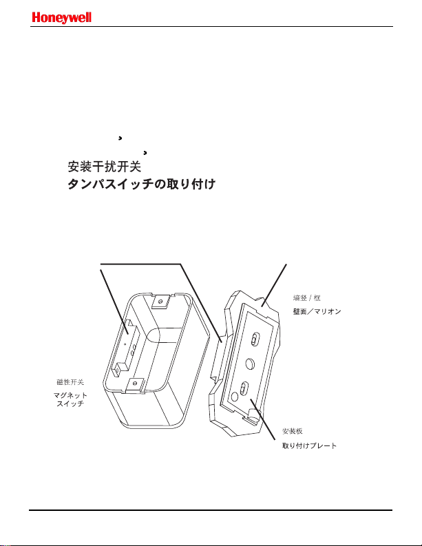
INSTALLTAMPER SWITCH
INSTALACION DEL INTERRUPTOR
1
DE SABOTAJE
`
INSTALLTAMPER SWITCH
INSTALACAO DO INTERRUPTOR
ANTI-VIOLACAO
~
~
INSTALLATION DES SABOTAGESCHUTZES
INSTALLAZIONE INTERRUTTORE
MANOMISSIONE
Magnetic
Switch
Interruptor
`
magnetico
Commutateur
`
magnetique
Interruptor
`
magnetico
Magnetschalter
Interruttore
magnetico
OmniClass Reader Installation Guide
Wall Surface
Muro / Mainel
Mur / Montant
Parede / Mainel
Wand / Mittelpfosten
Parete / Montante
Mounting Plate
Platina
Plaque de montage
Suporte de montagem
Montegeplatte
Piastra di montaggio
© 2005 Honeywell International. 1 Part Number 7-901036-00
Page 4

OmniClass Reader Installation Guide
INSTALLTAMPER SWITCH
INSTALACION DEL INTERRUPTOR
1
DE SABOTAJE
`
INSTALLTAMPER SWITCH
INSTALACAO DO INTERRUPTOR
ANTI-VIOLACAO
~
~
INSTALLATION DES SABOTAGESCHUTZES
INSTALLAZIONE INTERRUTTORE
MANOMISSIONE
An internal magnet provides tamper indication when used with a magnetic reed
switch connected to an external alarm system. (Except OM30).
`
Un iman interno permite la activacion de una senal de sabotaje cuando se utiliza
un conmutador de lamina externo.(Excepto en OM30).
Un aimant interne indique les intrusions lorsqu'il est utilise avec un commutateur
peigne magnetique connecte a un systeme d'alarme externe. (Sauf OM30).
~
`
Um ima interno proporciona a capacidade de indicacao de violacao quando
utilizado com um interruptor de lamina magnetico conectado a um sistema
de alarme externo. (Exceto no modelo OM30).
(OM30
Ein interner Magnet bietet Sabotageschutz, wenn er zusammen mit einem
magnetischen Reed-Schalter verwendet wird,der anein externes Alarmsystem
angeschlossen ist. (Au er OM30).
Un magnete interno fornisce indicazione di manomissione quando usato con un
interruttore a lamella magnetico collegato a un impianto di allarme esterno.
(Eccetto OM30).
`
``
(OM30
`
``
v
~
`
~
`
~
© 2005 Honeywell International 2 Part Number 7-901036-00
Page 5

ASSEMBLY AND DISASSEMBLY
MONTAJEY DESMONTAJE
2
MONTAGE ET DEMONTAGE
MONTAGEM E DESMONTAGEM
ZUSAMMENBAU UND ZERLEGUNG
MONTAGGIO E SMONTAGGIO
`
OM30 / OM40 / OM45
3
OmniClass Reader Installation Guide
1
2
OM55
© 2005 Honeywell International. 3 Part Number 7-901036-00
Page 6
OmniClass Reader Installation Guide
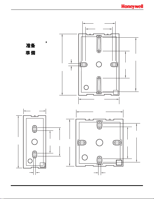
PREPARING
PREPARACION
3
PREPARATION
PREPARACAO
VORBEREITUNG
PREPARAZIONE
4.14 cm
3.75"
9.53 cm
`
1.63"
~
1.60"
4.06 cm
2.44"
`
.156"
.40 cm
4.49"
11.40 cm
6.20 cm
2.00"
5.08 cm
2.99"
7.59 cm
2.00"
5.08 cm
4.00"
10.16 cm
OM40
2.99"
7.59 cm
2.44"
6.20 cm
2.04"
5.18 cm
2.99"
7.59 cm
2.00"
5.08 cm
.156"
.40 cm
.156"
.40 cm
OM30 OM45
© 2005 Honeywell International 4 Part Number 7-901036-00
Page 7

PREPARING
PREPARACION
3
PREPARATION
PREPARACAO
VORBEREITUNG
PREPARAZIONE
OmniClass Reader Installation Guide
`
`
~
OM55
© 2005 Honeywell International. 5 Part Number 7-901036-00
Page 8

OmniClass Reader Installation Guide
4
ENGLISH Wiring digram
red +DC (10-16 VDC)
black ground
green Data 0 (data)
white Data 1 (clock)
drain **shield ground
orange *green LED
brown *red LED
yellow *speaker
blue *hold
violet *card presented
*optional connections
**Drain wire can be "data return"
line when a separate power
supply is used
FRANCAIS Schema de cablage
rouge +CC (5-16V cc)
noir terre
vert donnees 0 ("data")
blanc donnees 1 ("clock")
branch. supp. **mise a la terre
orange *voyant vert
marron *voyant rouge
jaune *bip
bleu *attente
violet *carte presente (OM55)
*connexions facultatives
**Le branchement supplementaire
peut servir de ligne de retour de
donnees en cas d'utilisation d'une
alimentation electrique separee
© 2005 Honeywell International 6 Part Number 7-901036-00
(OM55)
c
`
`
`
`
blindee
`
`
`
`
``
~
ESPANOL Diagrama de cableado
rojo +CC (10-16 VCC)
negro tierra
verde Data 0 (datos)
blanco Dato 1 (reloj)
malla **blindaje de tierra
naranja *LED verde
marron *LED rojo
amarillo *altavoz
azul *entrada de retencion
violeta *tarjeta presentada (OM55)
*conexiones opcionales
**El hilo de drenaje puede utilizarse
como linea de retorno cuando se
utiliza una fuente de alimentacion
independiente
PORTUGUES Diagrama de ligacoes
vermelho CA+ (5-16 V CA)
preto terra
verde Dados 0 (dados)
branco Dados 1 (clock)
dreno **terra do gabinete
laranja *LED verde
marrom *LED vermelho
amarelo *biper
azul *reserva
violeta *placa presente (OM55)
*conexoes opcionais
**O fio do dreno pode ser a linha de
"retorno de dados" quando usada
uma fonte de energia separada
v
`
`
`
~
c
Page 9

4
g
OmniClass Reader Installation Guide
(OM55)
DEUTSCH Schaltplan
rot +Gleichstrom
schwarz erde
grun Daten 0 (Daten)
weiss Daten 1 (Zeit)
drain **schirmerde
orange *grune LED
braun *rote LED
gelb *signal
blau *halten
violett *karte vorhanden
*optionale Verbindungen
**Drainanschluss kann bei Verwen-
dung separater Stromzufuhr
Datenruckleitun
© 2005 Honeywell International. 7 Part Number 7-901036-00
..
(5-16 VDC)
..
(OM55)
sein
ITALIANO Schema di collegamento
rosso +DC (5-16 VDC)
nero terra
verde Dato 0 (dato)
bianco Dato 1 (clock)
cavo di terra **schermo di terra
arancione *LED verde
marrone *LED rosso
giallo *ronzatore
blu *memoria
viola *scheda attiva (OM55)
*connessioni opzionali
**Il cavo puo fare da "ritorno dati" se
viene utilizatto un alimentatore
separato
(OM55)
Page 10

OmniClass Reader Installation Guide
TESTING
PRUEBA
5
TEST
TESTE
TESTEN
TESTARE
Turn pow er o n
Encienda la unidad
Mettez sous tension
Ligar energia
Strom einschalten
Accendere
© 2005 Honeywell International 8 Part Number 7-901036-00
Tes t ca rd
Pruebe la tarjeta
Testez la carte
Placadeteste
Kartentest
Tes t
Page 11

OmniClass Reader Installation Guide
OPTIONAL FEATURES
* Configuration Options - Configure LED, Speaker, keypad operation, keypad
6
lighting, and other features. See How to Order Guide or OmniClass
Application Note for details.
* Hold Input - when asserted, this line either buffers a card or disables a
card read until released,as configured.
CARACTERISTICAS OPCIONALES
* Opciones de configuracion - Permite configurar el Led, altavoz y otras
`
caracteristicas. Para mas detalles, consulte la Guia Como Hacer su Pedido
o la Nota de Aplicacion de OmniClass.
* Entrada de retencion - Segun sea la configuracion, cuando esta linea se
activa, se almacena el valor de la ultima tarjeta leida o se deshabilita la
lectura. Esto sucedera mientras esta linea permanezca activada.
`
`
``
`
`
`
`
`
`
`
`
`
FONCTIONNALITES EN OPTION
* Options de configuration - Configure l'affichage LED,le haut-parleur et
d'autres fonctionnalites.Voir le guide How To Order (Comment
commander) ou la note d'application intitulee OmniClass pour plus de
`
details.
* Entree suspendue - Quand il est mis en euvre, ce circuit met une carte en
`
tampon ou desactive provisoirement la lecture d'une carte, selon la
`
`
o
`
configuration choisie.
RECURSOS OPCIONAIS
~
c
* Opcoes de configuracao - configura o LED,o alto-falante e os outros
recursos. Para obter maiores detalhes, consulte o guia "Como fazer seu
pedido" ou a observacao de aplicacao do OmniClass.
* Bloqueio de entrada de sinal - quando ativada, esta linha impede a
~
c
utilizacao do cartao lido, ou desativa o cartao lido,ate o momento em
que for liberado,de acordo com a configuracao.
© 2005 Honeywell International. 9 Part Number 7-901036-00
~
c
~
c
~
~
c
~
`
~
c
Page 12

OmniClass Reader Installation Guide
6
*
*
*
*
OmniClassOmniClass
OmniClass
OPTIONALE FUNKTIONEN
* Konfigurationsoptionen - LED,Lautsprecher und anderes konfigurieren.
..
Nahere Informationen unter Auftragsleitfaden oder OmniClass
Anwendungshinweis.
* Halteeingang - wenn aktiviert, puffert diese Leitung entweder eine Karte
oder deaktiviert eine Kartenlesung bis zur Freigabe, je nach
Konfiguration.
FUNZIONI OPZIONALI
* Opzioni di configurazione - per configurare il LED,lo speaker e altre
funzioni. Per dettagli, vedere la guida alle ordinazioni o la nota applicativa
OmniClass.
* Ingresso trattenuta - quando viene attivata, questa linea mette in buffer
una scheda o diabilita una scheda, secondo la configurazione.
FCC Warning
This device complies with part 15 of the FCC rules.
Operation is subject to the following two conditions:
(1) This device may not cause harmful interference.
(2) This device must accept any interference that may cause undesired operation.
* For proper regulatory compliance, the drainwire should be disconnec tedat the power
supply end of the cable.
* Changes or modifications not expressly approved by the party responsible for
compliance could void the user's authority to operate the equipment.
* The Reader is intended to be powered from a limited power source output of a
previously certified power supply.
© 2005 Honeywell International 10 Part Number 7-901036-00
Page 13

OmniClass Reader Installation Guide
PAR TS
* 1 - Reader
* 1 - Installation Manual
7
* 2 - 3.5 mm x .6 pitch x 12 mm
Phillips machine screws
* 3 - 6-32 x .375" Phillips self-
tapping machine screws
* 2 - 6 x 1.5" Phillips sheet
metal screws
* 1 - 6-32 x .375 Spanner
security screw
* 1 - Mounting Gasket
RECOMMENDED
* Up to 10 wire splices
* Cable, 9 conductor,22AWG,
shielded (Wiegand)
* Cable, 6 conductor,22AWG,
shielded (Serial)
* Metal or plastic junction box
* Magnetic switch - Ademco
945T,Sentrol 1038T, GRI 100T,
or 110T or Aleph DC-2531
* Security Tool(for security
screw)
SPECIFICATIONS
Dimensions
Max. Read Range
Cable distance to host
Operating Temperature
Operating Humidity
Operating Voltage Range
Current
Tamper Output
1
Actual operating distance will vary depending upon installation environment
and proximity to metal
1
1.90 x 4.04 x .80 in.
4.83 x 10.26 x 2.03 cm
65 mA avg,225 mA
COMPONENTES
* 1 - lector
* 1 - manual de instalacion
* 2 - Tornillos Phillips de 3.5mm
x 12mm, paso 0.6
* 3 - Tornillos autoper forantes
o
N. 6 para metales Phillips
32 x 0.375"
* 1 - Tornillo de seguridad N.
contra sabotaje 0.375"
RECOMENDADO
* 9 empalmes para cable
* 1 cable, 5-9 conductores
(Wiegand o Rs-232) blindado
22AWG
* Fuente de alimentacion
lineal CC
* Caja de conexiones metalica
o de plastico
* Interruptor magnetico,
Ademco 945T,Sentrol 1038T,
GRI 100T,GRI110T o Aleph
DC-2531
* Herramienta de seguridad
(para tornillo contra sabotaje)
ESPECIFICACIONES
OM30
3.0" (7.6 cm)
500' (152 m) max
-30 to 150 deg F (-35 to 65 deg C)
5 - 95% relative humidity,non-condensing
peak at 12 VDC
10 - 16 VDC
No
`
`
3.30 x 4.80 x .85 in
8.38 x 12.19 x 2.16 cm
4.5" (11.4 cm)
80 mA avg,260 mA
peak at 12 VDC
Tamper magnet
`
o
`
`
OM40
© 2005 Honeywell International. 11 Part Number 7-901036-00
Page 14

OmniClass Reader Installation Guide
`
PIECES
* 1 - lecteur
* 1 - manuel d'installation
7
`
* Vis mecaniques Phillips 2 3,5
mm x 0.66 (pas) x 12
* 3 - Vis mecaniques Phillips
* 1 - vis de securite anti-intrusion
RECOMMANDES
* 9 flutes de jonction de fil
* 1 cable, 5-9 conducteurs (Wie-
* Alimentation c.c. lineaire
* Boitier de jonction metallique
* Commutateur magnetique -
* Outil de securite (pour vis anti-
`
autotaraudeuses #6-32 x
0,375"
`
`
v
`
a tete carree #6 x 0.375"
gand ou RS-232), calibre
22AWG,blinde
ou plastique
Ademco 945T,Sentrol 1038T,
GRI 100T ou 110T ou Aleph
DC-2531
intrusion)
`
v
v
`
`
`
`
`
`
`
FICHE TECHNIQUE
OM45
Dimensions
Max. Read Range
Cable distance to host
Operating Temperature
Operating Humidity
Operating Voltage Range
Current
Tamper Output
1
Actual operating distance will vary depending upon installation environment
and proximity to metal
1
3.30 x 3.30 x .75 in.
8.38 x 8.38 x 1.91 cm
3.0" (7.6 cm)
5 - 95% relative humidity,non-condensing
80 mA avg,260 mA
peak at 12 VDC
c
PECAS
*1-leitora
* 1 - manual de instalacao
* 2 - parafusos Phillips para
aplicacao a maquina de
3,5 mm x 0,6 de passo x
12 mm
* 3 - parafusos Phillips no 6 de
auto-rosqueamento para
aplicacao a maquina de 32
x 0,375 pol.
* 1 - parafusos de seguranca de
pino no 6 x 0,375 pol., antiviolacao
RECOMENDA-SE
* 9 emendas de fio
* 1 cabo,condutor 5-9, (Wiegand
ou RS232), 22AWG revestido
* Fonte de energia CD linear
* Caixa de juncao metalica ou
`
plastica
* Interruptor magnetico - Ademco
945T,Sentrol 1038T, GRI 100T ou
110T,ou Aleph DC2531
* Ferramenta de seguranca (para
o parafuso anto-violacao)
ESPECIFICACOES
500' (152 m) max
-30 to 150 deg F (-35 to 65 deg C)
10-16VDC
Tamper magnet
~
`
c
`
~
`
`
c
~
c
~
c
`
~
c
OM55
3.30 x 4.80 x .93 in
8.38 x 12.19 x 2.36 cm
4.0" (10.1 cm)
72 mA avg,244 mA
peak at 12 VDC
~
c
c
`
c
~
c
© 2005 Honeywell International 12 Part Number 7-901036-00
Page 15

OmniClass Reader Installation Guide
*
7
*
*
*
*
*
*
*
*
*
*
Dimensions
Max. Read Range
Cable distance to host
Operating Temperature
Operating Humidity
Operating Voltage Range
Current
Tamper Output
1
Actual operating distance will vary depending upon installation environment
and proximity to metal
1
4.83 x 10.26 x 2.03 cm
*
*
*
*
*
*
*
*
*
*
*
OM30
1.90 x 4.04 x .80 in.
3.0" (7.6 cm)
5 - 95% relative humidity,non-condensing
65 mA avg,225 mA
peak at 12 VDC
500' (152 m) max
-30 to 150 deg F (-35 to 65 deg C)
10 - 16 VDC
No
OM40
3.30 x 4.80 x .85 in
8.38 x 12.19 x 2.16 cm
4.5" (11.4 cm)
80 mA avg,260 mA
peak at 12 VDC
Tamper magnet
© 2005 Honeywell International. 13 Part Number 7-901036-00
Page 16

OmniClass Reader Installation Guide
TEILE
* 1 - Lesegerat
* 1 - Installationshandbuch
7
* 2 - 3,5 mm x 12 mm Sech-
* 3 - 32 x 0,375" Sechskant-
* 1 - 0,375" Sechskantsicher-
EMPFOHLEN
* 9 Kabelverbinder
* 1 Kabel, 5-9 Leiter (Wiegand
oder RS-232), 22 AWG
geschirmt
* Lineare Gleichstromver-
sorgung
* Kabelkasten aus Metall oder
Plastik
* Magnetschalter,Ademco
945T,Sentrol 1038T, GRI 100T
oder 110T oder Aleph Dc-2531
* Sicherheitswerkzeug (fur die
Sabotage-Schutz-schraube)
..
skantschraube (Gewindesteigung 6)
schneidschraube Nr.6
heitsschraube, SabotageSchutz
..
TECHNISCHE DATEN
Dimensions
Max. Read Range
Cable distance to host
Operating Temperature
Operating Humidity
Operating Voltage Range
Current
Tamper Output
1
Actual operating distance will vary depending upon installation environment
and proximity to metal
1
3.30 x 3.30 x .75 in.
8.38 x 8.38 x 1.91 cm
3.0" (7.6 cm)
5 - 95% relative humidity,non-condensing
80 mA avg,260 mA
peak at 12 VDC
COMPONENTI
*1-Lettore
* 1 - manuale di installazione
* 2 - viti da macchina Phillips 3,5
mm x passo 0,6 x 12 mm
* 3 - viti da macchina autofilettanti
Phillips numero 6-32 x 0,375
pollici
*1-vitedisicurezzaaprovadi
manomissione Spanner numero
6-32 x 0,375 pollici
CONSIGLIATI
* 9 giunti conduttore
* 1 cavo,5-9 conduttore ( Wiegand
o RS-232), schermato 22 AWG
* Alimentatore lineare c.c.
* Scatola di diunzione metallica o
in plastica
* Inerruttore magnetico Ademco
945T,Sentrol 1038T, GRI 100T o
Aleph DC-2531
* Utensile sicurezza (per vite a prova
di manomissione)
DATI TECNICI
OM45
500' (152 m) max
-30 to 150 deg F (-35 to 65 deg C)
10-16VDC
Tamper magnet
OM55
3.30 x 4.80 x .93 in
8.38 x 12.19 x 2.36 cm
4.0" (10.1 cm)
72 mA avg,244 mA
peak at 12 VDC
© 2005 Honeywell International 14 Part Number 7-901036-00
Page 17

OmniClass Reader Installation Guide
© 2005 Honeywell International. 15 Part Number 7-901036-00
Page 18

Honeywell Access Systems
135 West Forest Hill Avenue,
Oak Creek, WI 53154
Ph (414) 766-1700
Fax (414) 766-1798
www.honeywellaccess.com
NexWatch – Europe
Boblingerstrasse 17, 71101
Schonaich, Germany
Ph +49 7031637784
Fax +49 7031637786
Specifications subject to change without notice.
© Honeywell International. All rights reserved.
Document 7-901036
Revision 00
 Loading...