

Honeywell NS2 Configuration Manual

NS2 Configuration Guide
Contents
Description . . . . . . . . . . . . . . . . . . . . . . . . . . . . . . . . . . . . . . . 1
Specifications . . . . . . . . . . . . . . . . . . . . . . . . . . . . . . . . . . . . . 1
Power . . . . . . . . . . . . . . . . . . . . . . . . . . . . . . . . . . . . . . . . 1
Backup Battery. . . . . . . . . . . . . . . . . . . . . . . . . . . . . . . . . 1
Secondary Backup Battery. . . . . . . . . . . . . . . . . . . . . . . . 1
Reader & Aux Power . . . . . . . . . . . . . . . . . . . . . . . . . . . . 1
Reader Wiring . . . . . . . . . . . . . . . . . . . . . . . . . . . . . . . . . 2
Supervised Input Wiring . . . . . . . . . . . . . . . . . . . . . . . . . 2
Inputs . . . . . . . . . . . . . . . . . . . . . . . . . . . . . . . . . . . . . . . . 2
Outputs . . . . . . . . . . . . . . . . . . . . . . . . . . . . . . . . . . . . . . . 3
Enclosure Specifications . . . . . . . . . . . . . . . . . . . . . . . . . 4
Communications & Wiring . . . . . . . . . . . . . . . . . . . . . . . 4
DIP Switch Settings . . . . . . . . . . . . . . . . . . . . . . . . . . . . . 5
Connection Schematic . . . . . . . . . . . . . . . . . . . . . . . . . . . 6
Configuration Diagrams . . . . . . . . . . . . . . . . . . . . . . . . . . . . . 7
RS-232 Connection . . . . . . . . . . . . . . . . . . . . . . . . . . . . . 7
RS-485 Connection . . . . . . . . . . . . . . . . . . . . . . . . . . . . . 8
NSLAN1 Connection. . . . . . . . . . . . . . . . . . . . . . . . . . . . 9
LANSRL100 Connection. . . . . . . . . . . . . . . . . . . . . . . . 10
LANSRLU1 Connection . . . . . . . . . . . . . . . . . . . . . . . . 11
Lease Line Modem Connection . . . . . . . . . . . . . . . . . . . 12
RS-485 Short Haul Modem Connection . . . . . . . . . . . . 13
RS-232 Short Haul Modem Connection . . . . . . . . . . . . 14
M-9600 Dial-up Modem, RS-485 Connection . . . . . . . 15
M-56K Dial-up Modem, RS-485 Connection . . . . . . . . 16
Fiber Converter to RS-485 Connection . . . . . . . . . . . . . 17
485-PCI/NS2 Panel Connection Detail . . . . . . . . . . . . . 18
Frequently Asked Questions
. . . . . . . . . . . . . . . . . . . . . . . . . . . . 19
Description
The NS2 is a two reader panel providing access control for up
to two doors through the use of Wiegand readers.
The NS2 may be used as a standalone panel with independent
card and transaction storage or, with a software upgrade, as a
fully monitored online access control device. Communication
to the front-end computer is achieved through an RS-232 serial
cable (included with installation kit) or an optional RS-485
interface. Each RS-485 interface is capable of communicating
with up to 31 panels.
The NS2 is designed for tile mount using the ENC10 enclosure. The I/O terminals are organized by operational utility
with connectors for power and RS-485 communications
located on the lower right followed from right to left by the
relays, auxiliary power, door control inputs, and readers. The
Tamper and External Power Fail terminal are located at the left
edge above the main line of connectors.
Specifications
Power
AC Non-Polarized:
16.5 VAC utilizing a UL-listed 50 VA Class 2 transformer
(TB9-4 AC+/TB9-5 AC–)
or
DC Polarized:
24 VDC, 1.25 Amp (TB9-4 DC+/TB9-5 DC–)
Power Wire
Two-wire, 18 AWG, shielded cable.
Backup Battery
Casil 12 VDC (NCI Part #: BAT-3) 4Ah, sealed acid/lead
backup battery (J6 DC+/J7 DC–)
Backup battery will provide 2.5 hours of standby backup
power.
Charging voltage: 13.7 +/– 0.1 VDC
NOTE: The NS2 panel has deep discharge protection built in for the
protection of the battery and will only utilize a backup battery down to
10.2 VDC before the NS2 shuts down. Backup battery should be
replaced 2 to 2.5 years: more often if panel has a high rate of backup
use.
Secondary Backup Battery
The NS2 panel memory is backed up using a super capacitor
for one week in the absence of power or a backup battery. The
super capacitor will backup panel memory and real-time clock
and does not require maintenance or replacement.
Reader & Aux Power
Reader and AUX power is supplied at 10.8-12.7 VDC with a
maximum current of 600 mA.
Five volt (5 VDC) readers require five-volt regulators (Northern part no. 5VRDREG)
Maximum draw is less then 600 mA: (Reader 1+ Reader 2 +
Aux Power) < 600 mA.
NOTE: Aux power must not be used to power locks.
7-101004-01 1
NS2 Configuration Guide Honeywell Access Systems
Reader Wiring
Each reader port supports a single 12-volt reader with Wiegand
output format.
Reader 1 Terminal Wire Color Wiegrand Reader
TB3-1 Brown LED Control
TB3-2 Green Data 0 Signal
TB3-3 White Data 1 Signal
TB3-4 Black Common
TB3-5 Red 12VDC Power
TB3-6 Variable Tamper
Reader 2 Terminal Wire Color Wiegrand Reader
TB4-1 Brown LED Control
TB4-2 Green Data 0 Signal
TB4-3 White Data 1 Signal
TB4-4 Black Common
TB4-5 Red 12VDC Power
TB4-6 Variable Tamper
NS2 version 1.01.01 - 1.03.09 supports only the defaulted Wiegand formats:
F=PN 1 26 S 1 D 1 B1 B2 B3 B4
F=PN 2 32 S 0 D 0 B1 B2 B3 B4
F=PN 3 34 S 1 D 1 B1 B2 B3 B4
NOTE: NS2 version 1.01.01 - 1.02.04 at this time does not support
the ABA card format, the OL, OJ, and OH Options, Anti- Passback
and Lock Down Time.
NOTE: NS2 version 1.03.09 does not support the ABA card format
or the Lock Down Time option, but does support the NS2MEM module, the OL, OJ, and OH Options, as well as Anti-Passback (In card
only mode).
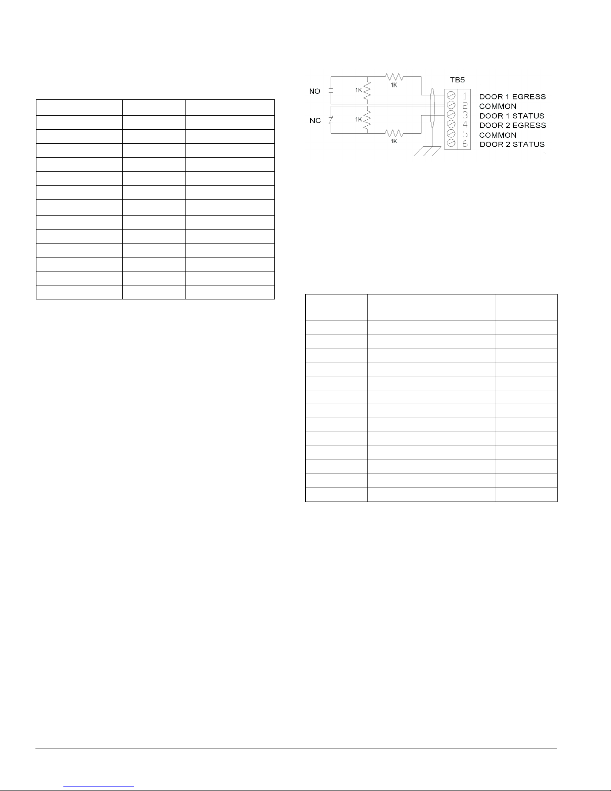
Supervised Input Wiring
The NS2 supervises inputs 1 through 8 and may be configured
for supervised or non-supervised normally open or normally
closed contacts. Use standard 1K ohm 5% resistors for supervision.
All eight inputs are assigned default features but can be
changed for other configurations as needed.
Inputs
The NS2 has 8 input points located on the following terminals:
Input
Ter mi nal
TB5-1 Door 1 Rex 1
TB5-3 Door 1 Status 2
TB5-2 Door 1 & 2 Common 1 & 2
TB5-4 Door 2 Rex 3
TB5-6 Door 2 Status 4
TB5-5 Input 3 & 4 Common 3 & 4
TB3-6 Reader Tamper or Aux Input 5 5
TB3-5 Common (Input 5 Common) 5
TB4-6 Reader Tamper or Aux Input 6 6
TB4-4 Common (Input 6 Common) 6
TB1-3 Power Fail or Aux Input 7 7
TB1-1 Enclosure Tamper or Aux Input 8 8
TB1-2 Common (Input 7 & 8 Common) 7 & 8
Description
Input/Aux
Number
2 7-101004-01
NOTE: Tamper and External Power Fail are supervised and capable of being used as additional inputs if the default functionality is not
needed.
NOTE: The wire used for the inputs should be shielded and cannot
exceed 30 ohms over the entire length of the cable. Remember that the
distance from the panel to the door must be doubled to determine the
total resistance.
Honeywell Access Systems NS2 Configuration Guide
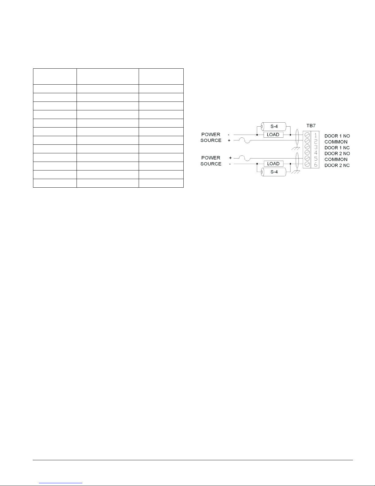
Outputs
Four form-C relays SPDT (Single Poll Double Throw) goldcontact relays are provided for controlling door locks or other
output devices (I.E. sounder, burg panel, phone dialer....etc.).
Output
Ter mi nal
TB7-1 Normally Open (NO) Relay 1 (Door 1)
TB7-2 Common (COM) Relay 1 (Door 1)
TB7-3 Normally Closed (NC) Relay 1 (Door 1)
TB7-4 Normally Open (NO) Relay 2 (Door 2)
TB7-5 Common (COM) Relay 2 (Door 2)
TB7-6 Normally Closed (NC) Relay 2 (Door 2)
TB8-1 Normally Open (NO) Relay 3
TB8-2 Common (COM) Relay 3
TB8-3 Normally Closed (NC) Relay 3
TB8-4 Normally Open (NO) Relay 4
TB8-5 Common (COM) Relay 4
TB8-6 Normally Closed (NC) Relay 4
Description
The energized or ON time for each relay can be configured by
using either time zone control, or programmable pulse time via
the host software.
Relay/Output
Number
Relay 1 is defaulted to control the Door 1 lock & Relay 2 is
defaulted for the Door 2 lock. Relay 3 & 4 are used as auxiliary
relays for signaling other devices. All 4 relays are rated at 12
Amps / 28VDC for resistive loads and 6 Amps / 28VDC for
inductive loads (data switching).
NOTE: Once the relay pole has been used for an inductive load
(including door strikes and magnetic locks) it should not be used for
low current dry circuit applications.
NOTE: Switching of inductive loads can cause EMI (Electromagnetic Interference) which may interfere with the normal operation of
other equipment.
To minimize premature contact failure and increase system
reliability, contact circuit protection such as the S-4 suppressor
is required. Locate this device as close as possible to the Door
Strike / Maglock.
7-101004-01 3

NS2 Configuration Guide Honeywell Access Systems
Enclosure Specifications
Mounting
One NS2 panel in a standard 19-inch, high density enclosure. Up to
eight NS2 panels in a single 19-inch rack mountable enclosure
Dimensions
Board 9-inch Length x 5.5-inch Wide x 1-inch High
Enclosure 12.5-inch Wide x 14.5-inch High x 3.5-inch Deep
Environmental
Temperature 35–110° F operational
Humidity 0–85% RHNC
Communications & Wiring
Communication Type Description Maximum Panels
Direct to COM Port
CBL50, RS-232 Cable 9-pin to RJ-45 1 50 15.25
N-485-PCI-2 RS-485 9-pin to CPU 31 4K 1219.5
Network
NSLAN1 Cobox Unit (RS-232)
LANSRL100/N-485-PCI-2L Ethernet to RS-485
LANSRLU1/N-485-PCI-2L Ethernet to RS-485
Modems
M-9600-LA (LO)/N-485-PCI Lease-line Modem to RS-485 31 NA/4K NA/1219.6
SHM-B-ASYNC/N-485-PCI Short-haul Modem to RS-485 31 5279.9/4K
SHM-B-ASYNC/CBL50 Short-haul Modem to RS-232 1 5279.9/50
M-9600-2/N-485-HUB-2 Dial-up Modem to RS-485 31 NA/4K NA/1219.6
M-56/N-485-HUB-2 Dial-up Modem to RS-485 31 NA/4K NA/1219.6
Fiber
FC485 Fiber converter to RS-485 31 10K/4K
1 NS2 panel per NSLAN1
64 max IP connections per system
31 NS2 panels per 485 interface
64 max IP connections per system
31 NS2 panels per 485 interface
64 max IP connections per system
Maximum Distance
Feet / Meters
328 100
328/4K 100/1219.6
328/4K 100/1219.6
1609.84/
1219.6
1609.84/
15.25
3049/
1219.6
Cable Specifications Description AWG
Readers
NC1861-BL 6 Conductor, Shielded 18 500 152.5
Alarm Input
NC1821-GR Twisted Pair, Shielded 18 2K 609.8
Relay Outputs
NC1821-GR Twisted Pair, Shielded 18 2K 609.8
NOTE: The C-100-A1/A2 (RS-232 communication loop), M-200 (1,200 Baud rate dial up modem), M-300-LO/LA
(1,200 Baud Leased line modem), F210D (Fiber to RS-232) [Discontinued] and F290D (Fiber to RS-485)
[Discontinued] are not supported with the NS2 panel(s).
4 7-101004-01
Maximum Distance
Feet / Meters

Honeywell Access Systems NS2 Configuration Guide
DIP Switch Settings
S1 S2 S3 S4 S5 S6 S7 S8 S9 S10 SELECTION
OFFOFFOFFOFFOFF
ON OFF OFF OFF OFF
OFF ON OFF OFF OFF
ON ON OFF OFF OFF
OFF OFF ON OFF OFF
ON OFF ON OFF OFF
OFF ON ON OFF OFF
ON ON ON OFF OFF
OFF OFF OFF ON OFF
ON OFF OFF ON OFF
OFF ON OFF ON OFF
ON ON OFF ON OFF
OFF OFF ON ON OFF
ON OFF ON ON OFF
OFF ON ON ON OFF
ON ON ON ON OFF
OFFOFFOFFOFF ON
ON OFF OFF OFF ON
OFFONOFFOFFON
ON ON OFF OFF ON
OFF OFF ON OFF ON
ON OFF ON OFF ON
OFF ON ON OFF ON
ON ON ON OFF ON
OFF OFF OFF ON ON
ON OFF OFF ON ON
OFF ON OFF ON ON
ON ON OFF ON ON
OFF OFF ON ON ON
ON OFF OFF ON ON
OFFONONONON
ON ON ON ON ON
OFF RS-232 (default)
ON RS-485 PCI Interface
OFF 19200 Baud (RS-232 only)
ON 57600 Baud (RS-232 only, default)
OFF OFF RS-485 Bias Off (default)
ON ON RS-485 Bias On
Address 0
Address 1(default)
Address 2
Address 3
Address 4
Address 5
Address 6
Address 7
Address 8
Address 9
Address 10
Address 11
Address 12
Address 13
Address 14
Address 15
Address 16
Address 17
Address 18
Address 19
Address 20
Address 21
Address 22
Address 23
Address 24
Address 25
Address 26
Address 27
Address 28
Address 29
Address 30
Address 31
OFF RS-485 EOL Off
ON RS-485 EOL On
7-101004-01 5
NS2 Configuration Guide Honeywell Access Systems
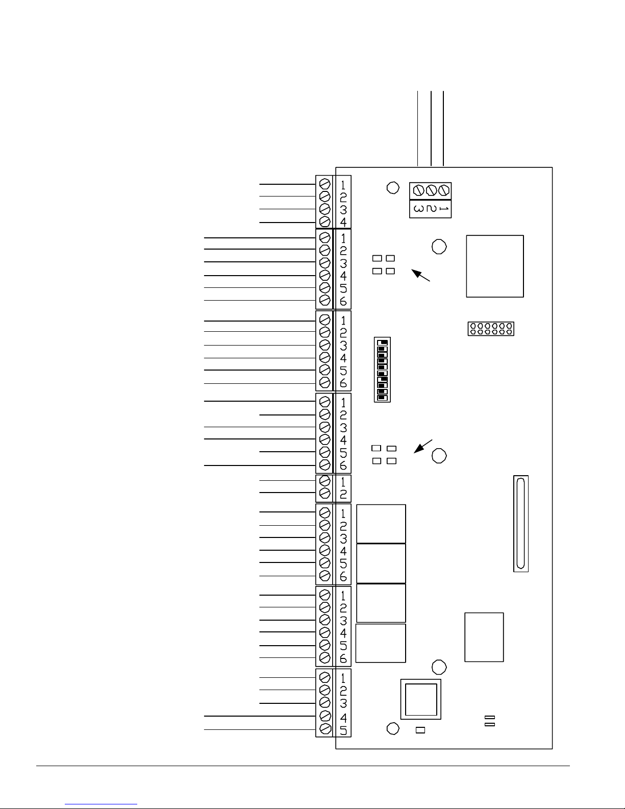
Connection Schematic
TB1
COMMON
PWR FAIL/AUX 7
ENC TMPR/AUX 8
RESERVED
RESERVED
RESERVED
RESERVED
LED
DA TA 0
DA TA 1
COMMON
+12V DC
RDR TMPR/A UX 5
LED
DA TA 0
DA TA 1
COMMON
+12V DC
RDR TMPR/A UX 6
C1
C2
SYSTEM STATUS
1ON
PF
RUN
LEDS
DIPSWITCHES
OPTIONAL
ETHERNET
INTERFA CE
READER1READER2
TB3
TB4
TB2
BROWN
GREEN
WHITE
BLA CK
RED
VARIES
BROWN
GREEN
WHITE
BLA CK
RED
VARIES
TB5
DR1 REX
DR1 STA TUS
DR2 REX
DR2 STA TUS
TB6
TB7
TB8
TB9
PWR ON L ED
PWR ON L ED
INPUT 1
COMMON
INPUT 2
INPUT 3
COMMON
INPUT 4
AUX +12VDC
AUX COM
RELAY1 NO
RELAY1 COM
RELAY1 NC
RELAY2 NO
RELAY2 COM
RELAY2 NC
RELAY3 NO
RELAY3 COM
RELAY3 NC
RELAY4 NO
RELAY4 COM
RELAY4 NC
RS485 +
RS485 -
RS4 85 COM
AC/DC +
AC/DC -
10
RELA Y LEDS
3
4
1
2
RELAY1
X PORT
RELAY2
RELAY3
RELAY4
RS- 23 2
POR T
J6 ( DC+)
J7 ( DC-)
POW ER L ED
BATTERY
6 7-101004-01
 Loading...