

Honeywell NS1 Installation Manual
NS1 Installation Guide
INTRODUCTION
Thank you for using NS1 for your access control application. NS1 is a powerful access control system
which can be used for single door access, as well as for connection to any type of on-line access control
system.
NS1 units can also be mounted in an RS485 network without the necessity of an external access control
system.
NS1 as a single door unit offers many possibilities such as:
• Access control
• Unlock option
• Day/Nightlock option (manual or automatic switching)
• Long range reader (up to 45cm)
• Optional use of PIN keypad
• Using an external relay (to prevent potential tampering)
• NS1 Manage software for stand-alone PC programming, event logging and user database
maintenance
REFERENCES
Master card usage is described in the NS1 User Guide (TD1168).
CONNECTIONS
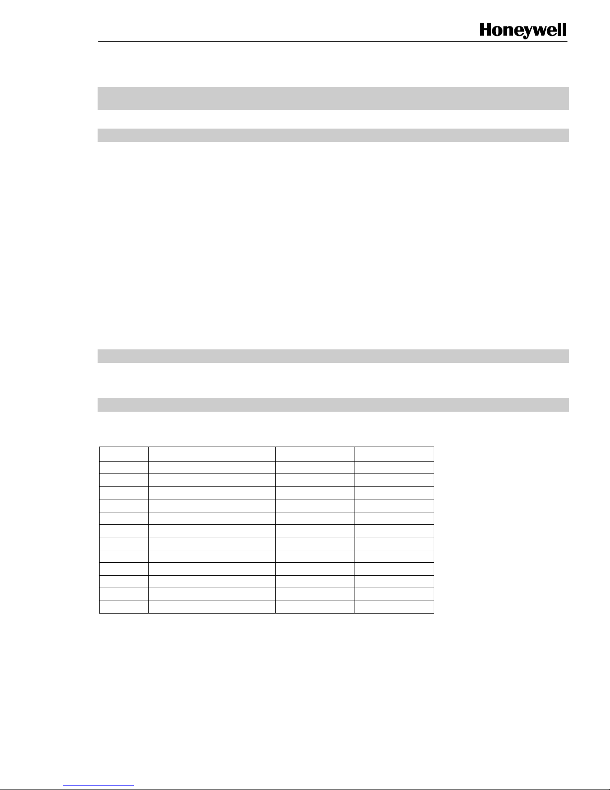
The NS1 uses 12 wire E111235 AWM STYLE 2560 60°C 30V low voltage computer cable. The
connections are indicated below.
Wire Stand-alone Magstripe (ABA) Wiegand
Brown Extra Ground
Violet Relay out (O.C)
Black Ground
Red Power (+11.5 … +12.5V DC)
Yellow RS-485B in +
Blue RS-485B out -
White RS-485A in +
Pink RS-485A out -
Grey IO-1 Door contact input \ RDP output DATA 0
Green IO-2 Ext. Night lock/Rex input \ RCP output DATA 1
Grey/Pink IO-3 Forced entry output \ CLS output STROBE
Red/Blue IO-4 Night lock enabled output \ Access input \ LED
TD1166 rev1003 1 - 8
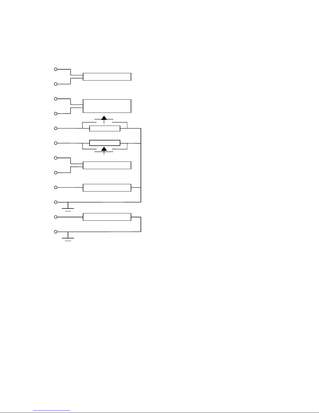
Figure 1 (below) gives a graphical representation of the connections.
A
pply
Wire
White
Controller
Yellow
Pink
Blue
Grey
Green
Grey / Pink
Red / Blue
Violet
Brown
Red
Black
Lock or external relay
Power su
Figure 1 NS1 Connections
Next reader or
Line Terminator
Door contact
External Clock
larm system
12V DC
NOTES:
1. The relay output is a 1A / 30V open collector.
2. With the NS1 only DC locks can be used when
directly connected to the NS1.
2 - 8 TD1166 rev1003
NS1 OPERATING LEVELS
The NS1 Proximity Reader has two operating levels:
• Installer Level. On this level the NS1 can be configured by the Installer. This level is also used to do
typical Installer options.
• User Level. On this level typical user options can be set, such as adding and voiding user cards,
setting the door open time, etc.
This Quick Guide explains the most frequently used Installer settings that can be used to configure the
NS1. Please refer to the NS1 User Guide (TD1168) for user related settings.
The programming steps mentioned in this Quick Guide represent a limited number of programming
functions that can be performed by the Installer on an NS1. Please refer to the NS1 Master Manual
(TD0099) for all the possibilities.
NS1 LEDS
The NS1 is provided with seven LEDs which serve as status indicators. Figure 2 illustrates their function.
Led 1 (yellow) Indicates that a card/remote programmer is within range of the NS1.
Led 2 (green) Indicates that access is granted or that the NS1 is in Unlock Mode.
Led 3 (red) Indicates that the door lock is closed.
Led 4 (red) Indicates that the NS1 is in Night Lock mode.
Led 5 (red) Indicates that the NS1 is in Add mode, and that cards are added.
Led 6 (red) Indicates that the NS1 is in Void mode, and that cards are voided.
Led 7 (red) Indicates that the NS1 is in Program mode.
Figure 2 LED indicators NS1
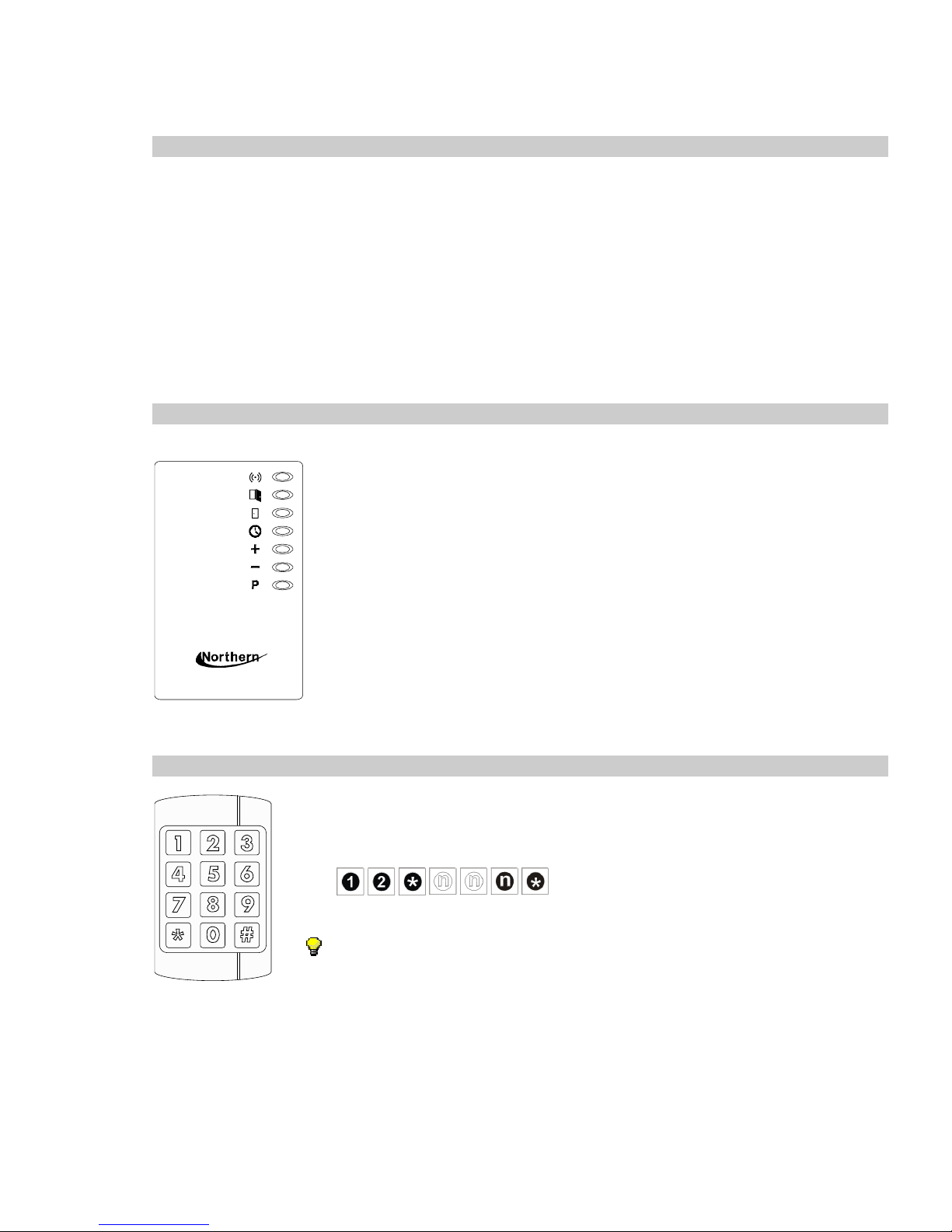
PROGRAMMING DEVICE
A remote programmer can be used to configure the NS1 and do settings in the NS1 by
bringing it into the RF field of the NS1.
1
2
3
5
4
7
6
8
9
0
#
*
In this Quick Guide, configuring the NS1 Proximity Reader is described by means of a Remote
Programmer. However, there are other ways. Northern also offers the possibility of programming the NS1
Proximity Reader through the NS1 Manage PC software.
If you have to install this application, please refer to the installation instructions of the NS1 Manage
manual (TD0099).
A programmed function may look like as follows:
The blank “n” in the function indicates an optional number.
An Installer Remote Programmer can set all functions of the NS1.
TD1166 rev1003 3 - 8
 Loading...