

Page 1
Manual Switches NR Series
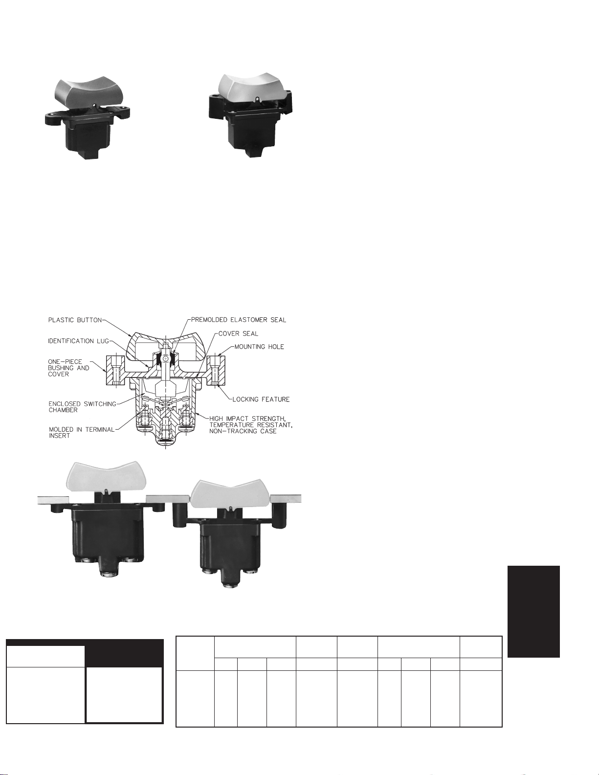
Sealed Rocker Switches
FEATURES
1 Completely sealed switching
chamber
1 Colored removable rockers
1 Choice of flush-panel or above-panel
mounting
1 Step-design case provides added
space between terminals to help
prevent shorting
1 1, 2 or 4-pole circuitry
GENERAL INFORMATION
MICRO SWITCH NR Series Rocker Switches meet severe environment application
needs for a rugged, cost-effective manual switch. They combine the advantages of
toggle switch circuit versatility with pushbutton control.
Quality construction features include a premolded elastomer seal between the actuator and bushing andanelastomer cover/case gasketseal. Also, the terminal inserts are
molded into the high impact strength thermoplastic case.
Complete sealing of the switching chamber enables compliance with UL 508, paragraph 13.3 hosedown test. These switches can beused wherepanels aresubjected to
periodic splash and washdowns, such as are common to food and beverage equipment. They will also withstand exposure to heavy accumulations of eary morning dew
that may condense on the control panel in cabs of vehicles left outdoors overnight.
1 2 or 3 positions, maintained and
momentary action
1 Spring-loaded actuating mechanism
provides excellent tactile feedback
1 High impact strength, non-tracking
case enhances electrical stability
1 Temperature range: −40 to 71°C
(−40 to 160°F)
1 UL recognized, File E12252, Vol. 1,
Section 44
1 CSA certified, File LR4442
1 CE approved
HOW TO ORDER
1. To order flush panel mount switches
without rockers,
specify the listings in
the NR order guides.
Above Panel Mount Flush Panel Mount
12PA ROCKER ORDER GUIDE
Note: These listings are used to specify
rockers only.
Rocker Catalog
Color Listing
White 12PA12-W
Red 12PA12-R
Yellow 12PA12-Y
Black 12PA12-BK
Green 12PA12-G
Blue 12PA12-BL
2. To specify above-panel mount
switches, change the1 (after ‘‘NR’’) in
1NR1, 11N R1, 2NR1,12NR1, 4NR1,and
14NR1 listings in the NR order guides
to 4. Example: 1NR1-2W converts to
1NR4-2, 11NR1-2 to 11NR4-2.
For 1NR91, 2NR91, and 14NR91 listings add 4 (after the ‘‘NR’’) to specify
the above panel mount version.Example: 1NR91-2 becomes 1NR491-2.
3. To order rockers, specify listings in
the 12PA rocker order guide.
ELECTRICAL RATINGS
L191: 15 amps, 125, 250, 277 VAC;
125 VAC; 1 Hp, 250, 277 VAC;
5 amps, 125 VAC ‘‘L’’
L192: 10 amps, 125, 250, 277 VAC;
125 VAC;
1
⁄2 Hp, 250, 277 VAC;
3 amps, 125 VAC ‘‘L’’
ELECTRICAL RATINGS
In Amperes (See Application Note on next page)
Elect.
Rating
Code Ind. Res. Lamp Res. Res. Ind. Res. Lamp Res.
1 12 20 5 0.75 0.5 10 15 3 6
2 10 15 4 0.75 0.5 7 15 2 6
3 15 20 7 0.75 0.5 15 15 4 6
4 10 18 5 0.75 0.5 8 11 2 6
5 12 20 5 0.75 0.5 15 15 4 6
6 10 18 4 0.75 0.5 8 11 2 6
28 Volts DC 115 VDC 250 VDC 60 & 400 Hz 230 VAC
115 Volts AC
1
⁄2 Hp,
1
⁄4 Hp,
Toggle/Rockers
Honeywell1SensingandControl11-800-537-6945USA1F1-815-235-6847International11-800-737-3360Canada123
Page 2
Manual Switches NR Series
Sealed Rocker Switches
NOTE: Catalog listings in the order
guides below do not include
rocker operators. See ‘‘How to
Order.’’
Application Note: Honeywell MICRO SWITCH does
not
recommend the use of silver
cadmium oxide switch contacts in non-arcing loads. Non-arcing loads are generally
loads less than 12 volts and/or 0.5 amp. NR switches use silver cadmium oxide
contacts. For other options, contact the MICRO SWITCH Application Center at
1-800-537-6945.
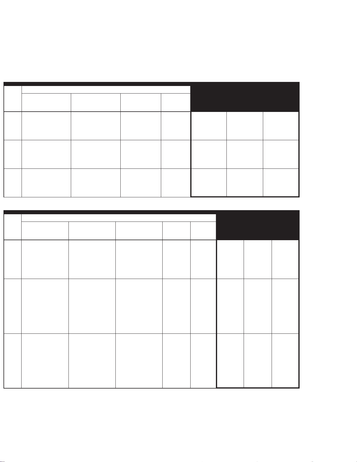
NR 2-POSITION FLUSH-PANEL MOUNT ROCKERS ORDER GUIDE
Circuits Made With Rocker At:
of
Poles
Ident. Lug
Position
OFF 2-3 L191 1 1NR1-2 11NR1-2 1NR91-2
1 1-2 2-3 L191 1 1NR1-3 11NR1-3 1NR91-3
OFF* 2-3 L192 2 1NR1-4 11NR1-4 1NR91-4
1-2* OFF L192 2 1NR1-6 11NR1-6 1NR91-6
1-2* 2-3 L192 2 1NR1-8 11NR1-8 1NR91-8
OFF 2-3, 5-6 L191 3 2NR1-2 12NR1-2 2NR91-2
2 1-2, 4-5 2-3, 5-6 L191 3 2NR1-3 12NR1-3 2NR91-3
OFF* 2-3, 4-6 L192 4 2NR1-4 12NR1-4 2NR91-4
1-2, 4-5* OFF L192 4 2NR1-6 12NR1-6 2NR91-6
1-2, 4-5* 2-3, 4-6 L192 4 2NR1-8 12NR1-8 2NR91-8
OFF 2-3, 5-6, 8-9, 11-12 L191 5 4NR1-2 14NR1-2 4NR91-2
4 1-2, 4-5, 7-8, 10-11 2-3, 5-6, 8-9, 11-12 L191 5 4NR1-3 14NR1-3 4NR91-3
OFF* 2-3, 5-6, 8-9, 11-12 L192 6 4NR1-4 14NR1-4 4NR91-4
1-2, 4-5, 7-8, 10-11* OFF L192 6 4NR1-6 14NR1-6 4NR91-6
1-2, 4-5, 7-8, 10-11* 2-3, 5-6, 8-9, 11-12 L192 6 4NR1-8 14NR1-8 4NR91-8
Opposite Lug
Position
UL Rating
Code
Elect.
Rating
Code Screw Solder Q-C
Termination StyleNo.
NR 3-POSITION FLUSH-PANEL MOUNT ROCKERS ORDER GUIDE
Circuits Made With Toggle At:
of
Poles
* These positions are momentary. All others are maintained.
** Toggle lever is blocked from these products. Toggle becomes 2-position, with center being one extreme position.
Ident. Lug
Position
1-2 OFF 2-3 L191 1 1NR1-1 11NR1-1 1NR91-1
1 1-2* OFF 2-3 L192 2 1NR1-5 11NR1-5 1NR91-5
1-2* OFF 2-3 * L192 2 1NR1-7 11NR1-7 1NR91-7
NONE** OFF 2-3 L191 1 1NR1-21 11NR1-21 1NR91-21
NONE** 1-2 2-3 L191 1 1NR1-31 11NR1-31 1NR91-31
NONE** 1-2 2-3* L192 2 1NR1-51 11NR1-51 1NR91-51
1-2* OFF NONE ** L192 2 1NR1-61 11NR1-61 1NR91-61
1-2, 4-5 OFF 2-3, 5-6 L191 3 2NR1-1 12NR1-1 2NR91-1
2 1-2, 4-5* OFF 2-3, 5-6 L192 4 2NR1-5 12NR1-5 2NR91-5
1-2, 4-5* OFF 2-3, 5-6 * L192 4 2NR1-7 12NR1-7 2NR91-7
NONE* OFF 2-3, 5-6 L191 3 2NR1-21 12NR1-21 2NR91-21
NONE** 1-2, 4-5 2-3, 5-6 L191 3 2NR1-31 12NR1-31 2NR91-31
NONE** 1-2, 4-5 2-3, 5-6* L192 4 2NR1-51 12NR1-51 2NR91-51
1-2, 4-5* OFF NONE ** L192 4 2NR1-61 12NR1-61 2NR91-61
1-2, 4-5 2-3, 4-5 2-3, 5-6 L191 3 2NR1-12 12NR1-12 2NR91-12
1-2, 4-5* 1-2, 5-6 2-3, 5-6 L192 4 2NR1-50 12NR1-50 2NR91-50
1-2, 4-5* 1-2, 5-6 2-3, 5-6* L192 4 2NR1-70 12NR1-70 2NR91-70
1-2, 4-5, 7-8, 10-11 OFF 2-3, 5-6, 8-9, 11-12 L191 5 4NR1-1 14NR1-1 4NR91-1
4 1-2, 4-5, 7-8, 10-11* OFF 2-3, 5-6, 8-9, 11-12 L192 6 4NR1-5 14NR1-5 4NR91-5
1-2, 4-5, 7-8, 10-11* OFF 2-3, 5-6, 8-9, 11-12* L192 6 4NR1-7 14NR1-7 4NR91-7
NONE* OFF 2-3, 5-6, 8-9, 11-12 L191 5 4NR1-21 14NR1-21 4NR91-21
NONE** 1-2, 4-5, 7-8, 10-11 2-3, 5-6, 8-9, 11-12 L191 5 4NR1-31 14NR1-31 4NR91-31
NONE** 1-2, 4-5, 7-8, 10-11 2-3, 5-6, 8-9, 11-12* L192 6 4NR1-51 14NR1-51 4NR91-51
1-2, 4-5, 7-8, 10-11* OFF NONE** L192 6 4NR1-61 14NR1-61 4NR91-61
1-2, 4-5, 7-8, 10-11 2-3, 4-5, 7-8, 11-12 2-3, 5-6, 8-9, 11-12 L191 5 4NR1-12 14NR1-12 4NR91-12
1-2, 4-5, 7-8, 10-11* 2-3, 4-5, 7-8, 11-12 2-3, 5-6, 8-9, 11-12 L192 6 4NR1-50 14NR1-50 4NR91-50
1-2, 4-5, 7-8, 10-11* 2-3, 4-5 2-3, 5-6, 8-9, 11-12* L192 6 4NR1-70 14NR1-70 4NR91-70
Center
Positon
Opposite Lug
Position
UL Rating
Code
Elect.
Rating
Code Screw Solder Q-C
Termination StyleNo.
TERMINAL CIRCUIT IDENTIFICATION
Terminal identification numbers referenced in the order guides
are molded into the switch base.
These numbers indicate which circuits are made in each rocker
position (e.g. ‘‘1-2’’ refers to circuit closure through terminals 1
and 2).
124Honeywell1SensingandControl11-800-537-6945USA1F1-815-235-6847International11-800-737-3360Canada
Page 3
Manual Switches NR Series
Seated Rocker Switches
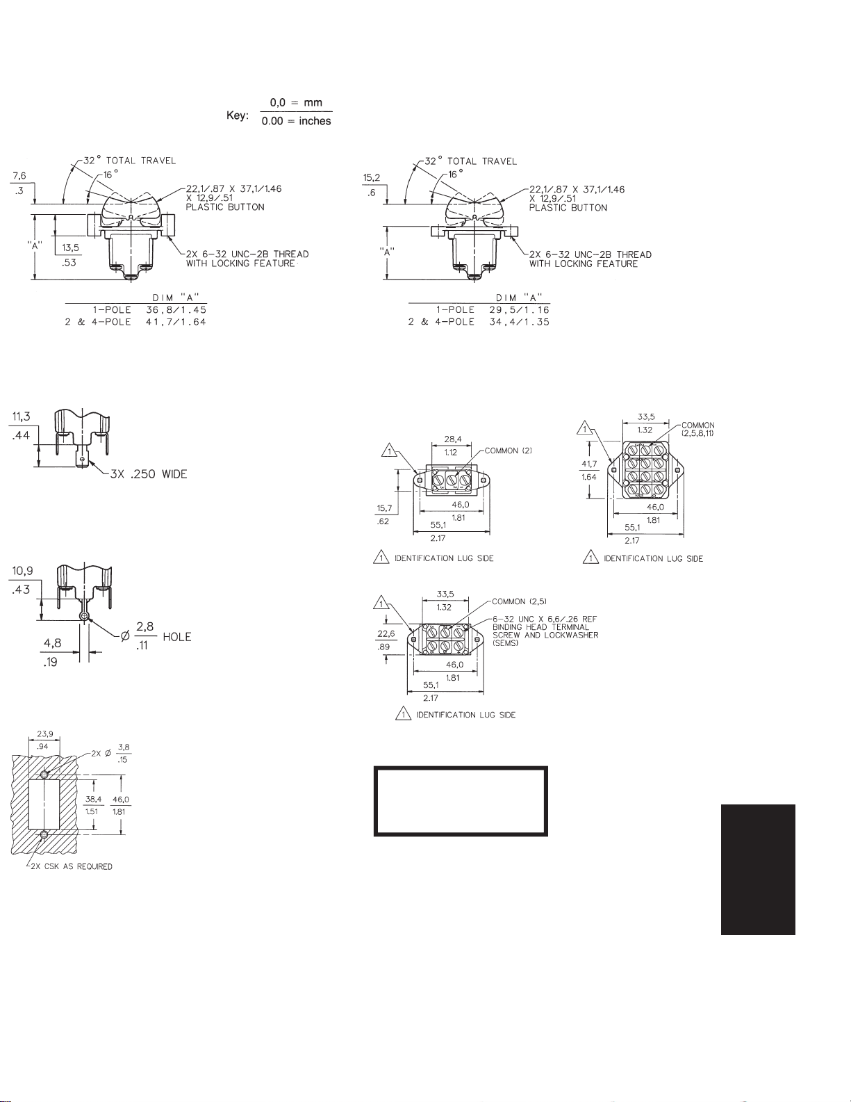
MOUNTING DIMENSIONS
(For reference only)
Flush Panel Above Panel
Quick Connect Terminals
Solder Terminals
Panel Cutout
Terminal Circuit Identification
Flange mounting torque is
10–12 in./lbs.
Terminal screw mounting
torque is 5 in./lbs. max.
Toggle/Rockers
Honeywell1SensingandControl11-800-537-6945USA1F1-815-235-6847International11-800-737-3360Canada125
Page 4

Manual Switches NT/NR Series
Flat Base Sealed Toggles and Rockers
FEATURES
1 Sealed switching chamber
1 1 or 2-pole circuitry
1 2 or 3 position maintained and
momentary action
1 Flat base with quick-connect
terminals – mating connectors are
available
1 Brightly colored removable rockers
1 Spring-loaded actuating mechanism
provides tactile feedback
1 High impact strength, non-tracking
case enhances electrical stability
1 Temperature range: –40 to 71°C (–40
to 160°F)
1 UL Recognized, File E12252, vol. 1,
section 44
UL AND CSA ELECTRICAL RATINGS
Rating Code* Electrical Rating
L192 10 amps, 125, 250, 277 VAC;1⁄4 Hp, 125 VAC;1⁄2 Hp, 250, 277 VAC; 3 amps,
L191 15 amps, 125, 250, 277 VAC;1⁄2 Hp, 125 VAC; 1 Hp, 250, 277 VAC; 5 amps,
ELECTRICAL RATINGS
In Amperes
Rating
Code Ind. Res. Lamp Res. Res. Ind. Res. Lamp Res.
1 12 20 5 0.75 0.5 10 15 3 6
2 10 15 4 0.75 0.5 7 15 2 6
3 15 20 7 0.75 0.5 15 15 4 6
4 10 18 5 0.75 0.5 8 11 2 6
Application Note: Honeywell MICRO SWITCH does
cadmium oxide switch contacts in non-arcing loads. Non-arcing loads are generally
loads less than 12 volts and/or 0.5 amp. NT/NR switches use silver cadmium oxide
contacts. For other options, contact the MICRO SWITCH Application Center at
1-800-537-6945.
125 VAC‘‘L’’
125 VAC‘‘L’’
28 Volts DC 115 VDC 250 VDC 60 & 400 Hz 230 VAC
115 Volts AC
not
recommend the use of silver
1 CSA Certified, File LR4442
1 CE approved
GENERAL INFORMATION
MICRO SWITCH NT Series toggle switches and NR Series rocker switches are
designed to meetsevere environment application needs for rugged, cost-effective
manual switches. These flat base style
products are identical to the stepped
base style in construction and features.
The flat base allows for PC board or connector use for easy wiring/connection.
The flat base NT toggle switches and NR
rocker switches are provided with quickconnect (spade) termination. Mating connectors are available.
TERMINAL CIRCUIT IDENTIFICATION
Terminal identifications are referenced in
the order guides to indicate which circuits
are made in each toggle position (e.g.
‘‘1-2’’ refers to circuit closure through terminals 1 and 2).
126Honeywell1SensingandControl11-800-537-6945USA1F1-815-235-6847International11-800-737-3360Canada
Page 5

Manual Switches NT Series
Flat Base Sealed Toggles
NT 2-POSITION ORDER GUIDE
Circuits Made At:
No. of
Poles
1 1-2 2-3 L191 1 31NT91-3
2 1-2, 4-5 2-3, 5-6 L191 3 32NT91-3
Keyway
Position
OFF 2-3 L191 1 31NT91-2
OFF** 2-3 L192 2 31NT91-4
1-2** OFF L192 2 31NT91-6
1-2** 2-3 L192 2 31NT91-8
OFF 2-3, 5-6 L191 3 32NT91-2
OFF** 2-3, 4-6 L192 4 32NT91-4
1-2, 4-5** OFF L192 4 32NT91-6
1-2, 4-5** 2-3, 4-6 L192 4 32NT91-8
Opposite
Keyway
UL Rating
Code
Electrical
Rating Code
Catalog
Listing
Toggle Q-C
NT 3-POSITION ORDER GUIDE
Circuits Made At:
No. of
Poles
1 1-2** OFF 2-3 L192 2 31NT91-5
2 1-2, 4-5** OFF 2-3, 5-6 L192 4 32NT91-5
** These positions are momentary. All others are maintained.
*** Toggle lever is blocked from these positions. Toggle becomes 2-position, with center being one extreme
position.
Keyway
Position
1-2 OFF 2-3 L191 1 31NT91-1
1-2** OFF 2-3** L192 2 31NT91-7
NONE*** OFF 2-3 L191 1 31NT91-21
NONE*** 1-2 2-3 L191 1 31NT91-31
NONE*** 1-2 2-3** L192 2 31NT91-51
1-2** OFF NONE*** L192 2 31NT91-61
1-2, 4-5 OFF 2-3, 5-6 L191 3 32NT91-1
1-2, 4-5** OFF 2-3, 5-6** L192 4 32NT91-7
NONE*** OFF 2-3, 5-6 L191 3 32NT91-21
NONE*** 1-2, 4-5 2-3, 5-6 L191 3 32NT91-31
NONE*** 1-2, 4-5 2-3, 5-6** L192 4 32NT91-51
1-2, 4-5** OFF NONE*** L192 4 32NT91-61
1-2, 4-5 2-3, 4-5 2-3, 5-6 L191 3 32NT91-12
1-2, 4-5 1-2, 5-6 2-3, 5-6 L191 3 32NT91-10
1-2, 4-5** 1-2, 5-6 2-3, 5-6 L192 4 32NT91-50
1-2, 4-5** 1-2, 5-6 2-3, 5-6** L192 4 32NT91-70
Center
Position
Opposite
Keyway
UL Rating
Code
Electrical
Rating
Code
Catalog
Listing
Toggle Q-C
MATING CONNECTORS ORDER GUIDE
Description Catalog Listing
2-pole connector 19PA168-NT
1-pole connector, same package size as 2-pole connector 19PA169-NT
LOCKING CONFIGURATIONS
ABDEFGH
Locked In Locked Out Of
Center and Locked Out Locked In Locked In Center And
Locked In Extreme Position Of Center Locked In Extreme Position Extreme Position Extreme Position
Three Positions (Keyway Side) Position Center Position (Opposite Keyway) (Keyway Side) (Keyway Side)
JKLMNP
Locked Out Of Locked In Locked Out Of Locked Out Of
Center And Center And Locked Out Of And Into Locked Out Of And Into
Extreme Position Extreme Position Extreme Position Extreme Position Extreme Position Extreme Position
(Opposite Keyway) (Opposite Keyway) (Keyway Side) (Opposite Keyway) (Opposite Keyway) (Keyway Side)
Honeywell1SensingandControl11-800-537-6945USA1F1-815-235-6847International11-800-737-3360Canada127
Toggle/Rockers
Page 6

Manual Switches NR Series
Flat Base Sealed Rockers
NR 2-POSITION ORDER GUIDE
Circuits Made At:
No. of
Poles
1 1-2 2-3 L191 1 31NR91-3
2 1-2, 4-5 2-3, 5-6 L191 3 32NR91-3
Keyway
Position
OFF 2-3 L191 1 31NT91-2
OFF** 2-3 L192 2 31NR91-4
1-2** OFF L192 2 31NR91-6
1-2** 2-3 L192 2 31NR91-8
OFF 2-3, 5-6 L191 3 32NR91-2
OFF** 2-3, 4-6 L192 4 32NR91-4
1-2, 4-5** OFF L192 4 32NR91-6
1-2, 4-5** 2-3, 4-6 L192 4 32NR91-8
Opposite
Keyway
UL Rating
Code
Electrical
Rating Code
Catalog
Listing
Rocker* Q-C
NT 3-POSITION ORDER GUIDE
Circuits Made At:
No. of
Poles
1 1-2** OFF 2-3 L192 2 31NR91-5
2 1-2, 4-5** OFF 2-3, 5-6 L192 4 32NR91-5
* Does not include rocker button. Order separately from chart.
** These positions are momentary. All others are maintained.
*** Toggle lever is blocked from these positions. Toggle becomes 2-position, with center being one extreme
position.
Keyway
Position
1-2 OFF 2-3 L191 1 31NR91-1
1-2** OFF 2-3** L192 2 31NR91-7
NONE*** OFF 2-3 L191 1 31NR91-21
NONE*** 1-2 2-3 L191 1 31NR91-31
NONE*** 1-2 2-3** L192 2 31NR91-51
1-2** OFF NONE*** L192 2 31NR91-61
1-2, 4-5 OFF 2-3, 5-6 L191 3 32NR91-1
1-2, 4-5** OFF 2-3, 5-6** L192 4 32NR91-7
NONE*** OFF 2-3, 5-6 L191 3 32NR91-21
NONE*** 1-2, 4-5 2-3, 5-6 L191 3 32NR91-31
NONE*** 1-2, 4-5 2-3, 5-6** L192 4 32NR91-51
1-2, 4-5** OFF NONE*** L192 4 32NR91-61
1-2, 4-5 2-3, 4-5 2-3, 5-6 L191 3 32NR91-12
1-2, 4-5 1-2, 5-6 2-3, 5-6 L191 3 32NR91-10
1-2, 4-5** 1-2, 5-6 2-3, 5-6 L192 4 32NR91-50
1-2, 4-5** 1-2, 5-6 2-3, 5-6** L192 4 32NR91-70
Center
Position
Opposite
Keyway
UL Rating
Code
Electrical
Rating
Code
Catalog
Listing
Rocker* Q-C
ELECTRICAL RATING
L191: 15 amps, 125, 250, 277 VAC;
1
⁄2 Hp,
125 VAC; 1 Hp, 250, 277 VAC; 5
amps, 125 VAC ‘‘L’’
L192: 10 amps,125, 250, 277 VAC;
125 VAC;
1
⁄2 Hp, 250, 277 VAC; 3
1
⁄4 Hp,
amps, 125 VAC ‘‘L’’
TERMINAL CIRCUIT
IDENTIFICATION
Terminal identifications are referenced in
the order guides to indicate which circuits
are made in each toggle position (e.g.,
‘‘1-2’’ refers to circuit closure through terminals 1 and 2).
Top specify above-panel mount rockers: add 4 (after the ‘‘NR’’) to specify the
above panel version. Example: 31NR91-5
becomes 31NR491-5.
ROCKER BUTTONS ORDER GUIDE
Rocker
Color
White 12PA12-W
Red 12PA12-R
Yellow 12PA12-Y
Black 12PA12-BK
Green 12PA12-G
Blue 12PA12-BL
Catalog
Listing
MATING CONNECTORS ORDER GUIDE
Description Catalog Listing
2-pole connector 19PA168-NT
1-pole connector, same package size as 2-pole connector 19PA169-NT
128Honeywell1SensingandControl11-800-537-6945USA1F1-815-235-6847International11-800-737-3360Canada
Page 7

Manual Switches NT/NR Series
Flat Base Sealed Toggles and Rockers
MOUNTING DIMENSIONS (For reference only)
Toggle Switches
Rocker Switches, Above Panel
Rocker Switches, Flush Panel
Flange mounting torque is 10–12 in./lbs.
Bushing mounting torque is 10–15 in./lbs.
Honeywell1SensingandControl11-800-537-6945USA1F1-815-235-6847International11-800-737-3360Canada129
Toggle/Rockers
 Loading...