

Page 1
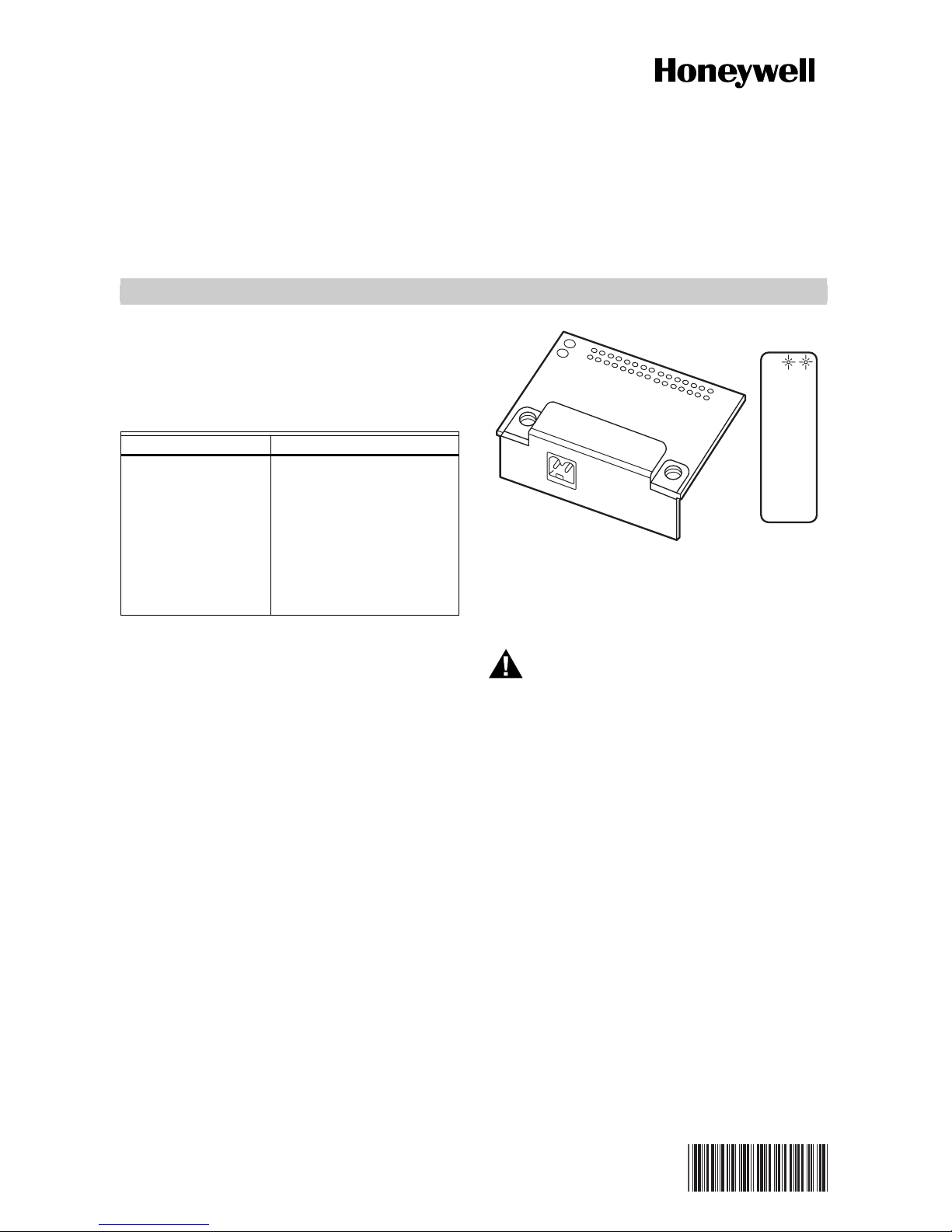
NPB-LON
APPLICATION
This document covers the mounting and wiring of the
NPB-LON option card in a WEB-201, CP-201 or
WebStat™ series controller.
Table 1. NPB-LON Option Description.
Description Notes
FTT-10A LON
(LonWorks) adapter
with 2-position
removable screwterminal connector plug.
For related mounting and wiring details, please see the
Mounting and Wiring Instructions document, form no.
95-7722.
Up to 2 LON
may be installed.
• If one Lon option, it
operates as LON1,
regardless of slot.
• If two LON options, LON1
is Option slot 1 and LON2
is Option slot 2.
See Fig. 2 for location of
option slots.
CONTENTS
Included in this package are the following items:
• An NPB-LON option card, along with connector end
plate.
• One 2-position terminal plug, for wiring to an FTT-10
LonWorks
• This NPB-LON Installation Instructions.
®
network.
®
option cards
INSTALLATION INSTRUCTIONS
RX TX
LON
M23324
Fig. 1. NPB-LON Option.
MOUNTING
WARNING
Power to the controller must be off when
installing or removing option cards or
damage will occur! Also, be very careful to
plug any option card into its connector
properly (pins aligned).
Mount the NPB-LON option card in either of the option
card slots of the controller as available. See the notes in
Table 1 about LON adapter software assignments if
installing two NPB-LON option cards.
MATERIAL AND TOOLS REQUIRED
The following tools and supplies may be required for
installation:
• #2 phillips screwdriver: use to install the NPB-LON.
• Small flat-blade screwdriver: used for making wiring
connections to the FTT-10 LonWorks network.
Mounting NPB-LON option card on a
controller
1. Remove power — See the above warning.
2. Remove the cover. To do this press the four tabs
on both ends of the unit and lift the cover off.
NOTE: If accessory modules are plugged into the con-
troller, they may need to be slid away from the
unit to get to the cover tabs.
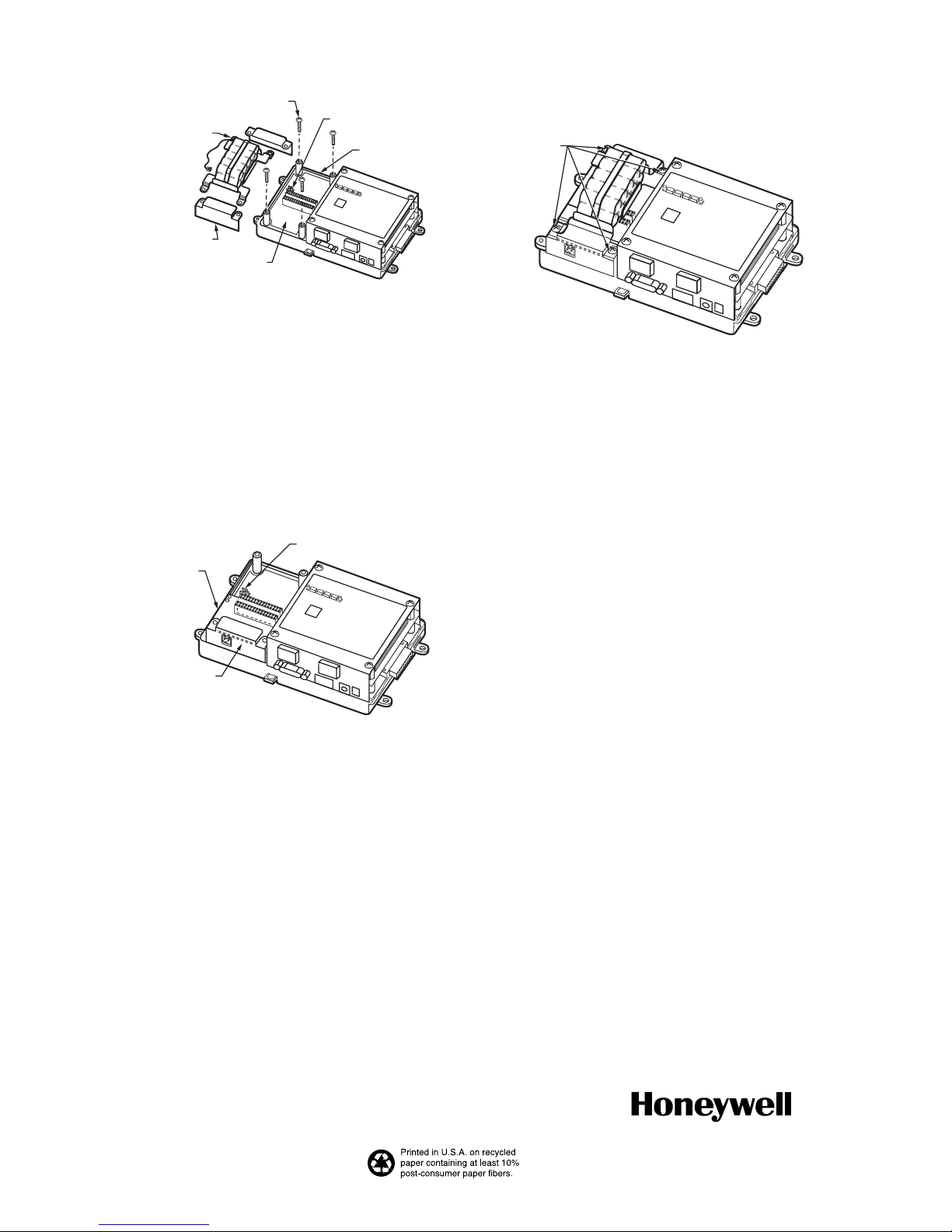
3. Remove the battery and bracket assembly by taking out the four screws holding it in place and set
them aside for later. Unplug the battery from the
connector on the controller (See Fig. 2).
62-0263
Page 2
NPB-LON
A
BATTERY ASSEMBLY
(INCLUDES CABLE
ND BRACKET)
BLANKING END
PLATE
SCREWS (4)
OPTION SLOT
1 AREA
UNPLUG BATTERY HERE
OPTION SLOT
2 AREA
M23694
Fig. 2. Remove Screws and Battery Assembly.
4. Remove the blanking end plate for the slot the
option card will be installed into (retain the blanking
end plate in case the option card is removed at a
later date).
5. Carefully insert the pins of the NPB-LON into the
socket of the appropriate option card slot. The
mounting holes on the option board should line up
with the standoffs on the base board. If they do not,
the connector is not properly aligned. Press until
the option card is completely seated.
6. Place the custom end plate that came with the
NPB_LON over its connector (See Fig. 3).
INSERT NPB-LON INTO
OPTION CARD SLOT
CAREFULLY, WITH
PINS ALIGNED. FULLY
SEAT CARD.
PLACE NPB-LON
CUSTOM END
PLATE OVER END
BATTERY
CONNECTOR
M23695
HAND TIGHTEN THE
FOUR SCREWS
THROUGH BATTERY
BRACKET, END
PLATES, INTO
STANDOFFS
M23327
Fig. 4. Re-Fasten Screws through Battery Bracket.
10. Replace the cover. If accessory modules were
unplugged, plug them back into the controller as
before and secure.
WIRING
Connect LonWorks FTT-10 communications wiring to the
2 position connector of the NPB-LON. Note that polarity
is not a factor in FTT-10 wiring.
Refer to the LonWorks FTT-10A Free Topology
Transceiver User’s Guide for technical guidelines
associated with free topology restrictions, and the
Junction Box and Wiring Guidelines for Twisted Pair
LonWorks Networks for more detailed information on
wiring specifications. These documents are available on
Echelon’s web site (www.echelon.com).
LEDS
Fig. 3. NPB-LON Inserted, End Plate on Top.
Two LEDs are visible on the top of the NPB-LON option
card (cover must be removed):
7. Plug the battery cable into the battery connector on
the controller (See Fig 3. for location).
8. Set the battery and bracket assembly back over
the option card slots, with the mounting holes
aligned with the standoffs.
9. Place the four screws through the battery bracket,
• RX (green) — Receive, indicates that another
LonWorks device is transmitting a message.
• TX (yellow) — Transmit, indicates that the controller is
transmitting a message on the LON trunk.
These LEDs are included on the top label of the NPB-
LON (See Fig.1).
end plates and into the standoffs on the controller
base board. Hand tighten these screws (See Fig.
4).
®
LON
AND LONWORKS® ARE REGISTERED TRADEMARKS OF ECHELON CORPORATION.
W
EBSTAT™ IS A TRADEMARK OF HONEYWELL INTERNATIONAL INC.
By using this Honeywell literature, you agree that Honeywell will have no liability for any damages arising
out of your use or modification to, the literature. You will defend and indemnify Honeywell, its affiliates
and subsidiaries, from and against any liability, cost, or damages, including attorneys’ fees, arising out
of, or resulting from, any modification to the literature by you.
Automation and Control Solutions
Honeywell International Inc. Honeywell Limited-Honeywell Limitée
1985 Douglas Drive North 35 Dynamic Drive
Golden Valley, MN 55422 Toronto, Ontario M1V 4Z9
customer.honeywell.com
® U.S. Registered Trademark
© 2007 Honeywell International Inc.
62-0263 J.I. 02-07
 Loading...