

Honeywell Notifier ST.PL4+ Installation And User Manual

Honeywell Life Safety Iberia
www.honeyw
elllifesafety.es
C/Pau Vila 15-19
08911 BADALONA (BARCELONA)
Tel.: 902 03 05 45
ST.PL4+
MANUAL DE USUARIO E INSTALACIÓN
INSTALLATION AND USER MANUAL
Toda la información contenida en este documento puede ser modificada sin previo aviso.
Information in this document is subject to change without notice.
MN-DT-516 / (MT3910)
13 JUNIO 2017 / 13 JUNE 2017

Manual de usuario e instalación
/ Installation and user manual
PL4+
MN-DT-516.doc (MT3910.doc) 13/06/2017 2 de 33

Manual de usuario e instalación
/ Installation and user manual
PL4+
ÍNDICE INDEX
1.1 Características técnicas ................................................................................... 7
1.1 Technical specification ..................................................................................... 7
1.2 Fusibles ........................................................................................................... 7
1.2 Fuses ............................................................................................................... 7
2.1 Fijación mecánica ............................................................................................ 8
2.1 Mechanical fixing ............................................................................................. 8
2.2 Diagram and part identification ........................................................................ 9
2.3 Equema del circuito base ................................................................................ 10
2.3 Main board layout .......................................................................................... 10
2.3.1 S
2.2.1 L
2.3.2 C
2.2.2. C
2.4 Módulo de ampliación .................................................................................... 14
2.3 Expansion Module ......................................................................................... 14
2.5 Prueba automática (Self-Test) ....................................................................... 15
2.4 Self-Test ........................................................................................................ 15
3.1 Alimentación principal (220Vca) .................................................................... 16
3.1 Main power supply (220Vac) ......................................................................... 16
3.2 Conexión de los detectores ........................................................................... 16
3.2 Detectors connection ..................................................................................... 16
3.3 Gas detectors positioning .............................................................................. 17
4.1 Panel frontal .................................................................................................. 18
4.1 The front panel .............................................................................................. 18
4.2 Conexión de baterías y primer encendido ..................................................... 19
4.2 Battery connection and first switching on ....................................................... 19
4.3 Configuración de la central ............................................................................ 19
4.3 SET mode ...................................................................................................... 19
4.4 Central en alarma .......................................................................................... 20
4.4 Alarm condition .............................................................................................. 20
4.5 Central en avería ........................................................................................... 20
4.5 Fault condition ............................................................................................... 20
4.6 Deshabilitar la central .................................................................................... 21
4.6 UNSET mode ................................................................................................ 21
4.7 Central en modo de programación ................................................................ 21
4.7 Programming mode ....................................................................................... 21
4.8 Alarma de batería baja .................................................................................. 21
4.8 Low battery alarm .......................................................................................... 21
4.9 Alarma fuera de rango ................................................................................... 22
ELECCIÓN DE IDIOMA
ANGUAGE SELECTION
ONEXIÓN BLOQUES DE TERMINALES
ONNECTION TERMINAL BLOCKS
................................................................................ 11
............................................................................... 11
.................................................................. 11
........................................................... 11
MN-DT-516.doc
(MT3910.doc)
13/06/2017 3 de 33

Manual de usuario e instalación
/ Installation and user manual
PL4+
4.9 Over range alarm ........................................................................................... 22
5.1 Ejemplo de programación de una entrada ..................................................... 24
5.1 Example of input channel programming ........................................................ 24
5.2 Programación de entrada de detector de oxígeno ............................................. 27
5.2 Oxygen detector input channel programming ................................................ 27
5.3 MENU TIEMPOS ........................................................................................... 28
5.3 "TIMES” menu ............................................................................................... 28
5.4 REARME de los parámetros por defecto de fábrica (versión de firmware 3.0)29
5.4 Default conditions RESET (firmware release 3.0 on)..................................... 29
MN-DT-516.doc
(MT3910.doc)
13/06/2017 4 de 33

Manual de usuario e instalación
/ Installation and user manual
PL4+
Avisos
Warning
TODA PERSONA RESPONSABLE DE LA
INSTALACIÓN, USO O MANTENIMIENTO DE
ESTE EQUIPO DEBE LEER EL MANUAL CON
ATENCIÓN.
Como cualquier equipo, este producto
funcionará correctamente solo si se instala, y
utiliza siguiendo las instrucciones del
fabricante. EN CASO CONTRARIO, PODRÍA
NO FUNCIONAR COMO SE ESPERA Y LAS
PERSONAS QUE CONFÍAN EN ESTE
EQUIPO PARA SU SEGURIDAD PODRÍAN
SUFRIR DAÑOS GRAVES O LETALES.
Las garantías de Sensitron s.r.l en relación a
este producto no son aplicables si éste no se
instala o utiliza según las instrucciones de este
manual. Protéjanse siguiendo dichas
instrucciones.
Recomendamos a nuestros clientes que se
pongan en contacto con nosotros si desean
información adicional relativa a este equipo
antes de proceder a su instalación o uso.
THIS MANUAL MUST BE CAREFULLY READ
BY ALL PERSONS WHO HAVE OR WILL
HAVE THE RESPONSIBILITY FOR
INSTALLING, USING OR SERVICING THIS
PRODUCT.
Like any equipment, this product will perform as
designed only if installed, used and serviced in
accordance with the manufacturer’s
instructions.
OTHERWISE, IT COULD FAIL TO PERFORM
AS DESIGNED AND PERSONS WHO RELY
ON THIS PRODUCT FOR THEIR SAFETY
COULD SUFFER SEVERE PERSONAL
INJURY OR DEATH.
We recommend our customers to write or call
The warranties made by Sensitron s.r.l. with
respect to this product are voided if the product
is not installed, used and serviced in
accordance with the instructions in this user
guide. Please protect yourself and others by
following them.
regarding this equipment prior to use or for any
additional information relative to use or repair.
MN-DT-516.doc
(MT3910.doc)
13/06/2017 5 de 33

Manual de usuario e instalación
/ Installation and user manual
PL4+
mite el reconocimiento de
20mA procedentes de
1
INTRODUCCIÓN
La central PL4+ per
1 INTRODUCTION
The PL4+ gas control panel can manage 4
señales del tipo 4sensores de gas. La central está diseñada
para gestionar 4 zonas y se puede expandir
hasta un total de 8 zonas mediante un módulo
de expansión de 4 zonas.
La PL4+ permite la conexión de detectores de
Oxígeno para tener control tanto sobre
exceso de Oxígeno como por deficiencia de
Oxígeno. En el caso de detectores de
Oxígeno, es recomendable disponer de una
PL4+ dedicada a los detectores de Oxígeno y
otra central para el resto de detectores. Los
detectores de oxígeno suelen tener ajustados
los umbrales de alarma para controlar la
deficiencia de oxígeno mientras que el resto
de detectores controlan el exceso de gas,
esto podría causar problemas de activación
del relé en una misma central.
Los valores de la concentración medidos son
presentados en la pantalla. Por cada entrada,
es posible fijar el tipo de detector, el campo de
medida, el fondo de escala y el valor de
señalización de alarmas. Las programaciones
de las funciones son efectuadas mediante las
teclas del frontal del panel.
La central dispone de 5 salidas de relé, una
para cada nivel de alarma (AL1, AL2, AL3),
una para avería (FLT) y una auxiliar (AUX)
que puede asociarse a cualquier estado de
alarma o avería.
Con la tarjeta de ampliación de 4 zonas,
además de aumentar en 4 zonas de entrada,
se puede disponer de 16 salidas de tensión
(colector abierto) asociadas a los niveles de
alarma 2 y alarma 3 de cada una de las 8
entradas.
analogue 4-20mA gas detectors and can be
expanded to 8 by using an optional 4-zone
expansion module, easily connectable directly
in the control unit.
PL4+ accepts also Oxygen detectors and
manages both its enrichment and depletion.
In the event that Oxygen detectors should be
managed along with detectors for other types
of gas, we recommend to have a PL4+
dedicated to the Oxygen detectors and
another panel for the other detectors, in that
oxygen detectors might have alarm thresholds
set to monitor its depletion while the other
gases are monitored to control the increasing
contents in the atmosphere and this might
cause problems in the relay activation.
On the front panel, a backlit LC display shows
the values being measured.
Any single input configuration requires setting
the type of detector being used, the measuring
range and the alarm thresholds. Functions
programming is easily performed through the
push buttons on the front panel.
The control panel is equipped with 5 relays
and precisely, one for each alarm threshold
(AL1, AL2, AL3), one for fault (FLT) and an
auxiliary one (AUX) that can be associated to
any of the alarm status or fault.
By adding the optional 4-zone expansion
module, the panel gets 4 additional inputs and
16 Open-Collector outputs (negative safety)
that can be associated to AL2 – AL3 alarms of
each of the 8 inputs.
MN-DT-516.doc
(MT3910.doc)
13/06/2017 6 de 33

Manual de usuario e instalación
/ Installation and user manual
PL4+
Fault
1.2 Fusibles
1.2 Fuses
F1
F1
1.1 Características técnicas 1.1 Technical specification
Cabina ABS IP65
Tensión de alimentación 220VcA +/- 10% Power supply 100-240 Vac
Consumo en reposo 60mA (Típico) (solo
Entradas (versión
básica)
Ampliación de entradas 4 analóg. 4-20 mA Input expansion 4 Analog 4-20 mA
Salidas (versión
básica)
Relés de contacto 1A, 24 Vcc o 0,5A 120 Vcc
Contactos de relé 250Vca-8A Contacts rating 250Vca-8A
Ampliación de salidas 16 colector abierto (AL 2 –
LEDs indicadores Alimentación principal,
486 x 288 x 148 mm
central)
4 analóg. 4-20 mA Inputs (base version) 4 Analog 4-20 mA
Relé Aux, Al.1, Al.2, Al.3,
Avería
(AUX 10A 125 Vca o 5A
24 Vcc)
AL 3 para los 8 canales)
baterías, salida auxiliar,
Preal. 1, Preal. 2, Alarma 3,
Avería.
Housing ABS IP65 box:
486 x 288 x 148 mm
Power consumption 60mA (Tipico – typical)
Outputs (basic version) Relays Aux, Al.1, Al.2, Al.3,
Fault
Contacts rating 1A, 24 Vdc or 0,5A 120 Vdc
(AUX 10A 125 Vac or 5 A
24 Vdc)
Extended Outputs 16 Open-Collector (AL 2 –
AL 3 for the 8 channels)
LED indications Main power supply,
battery supply,
auxiliary output
Pre-al. 1, pre-al. 2, Alarm 3,
Pantalla Pantalla LCD alfanumérica
Baterías de apoyo 12V 7A/h (opcional) Backup battery 12V 7A/h (Optional)
Temp. Funcionamiento 0-50 C° Operating temperature 0-50 C°
Humedad 15-85% sin condensación Humidity 15-85% non condensing
Conformidad CEM
(EMC)
Conformidad ATEX
retroiluminada de 2 líneas
x 16 columnas.
Requisitos de emisión
EN 61000-6-3 (emisiones
clase B – límites
residenciales).
Requisitos de inmunidad:
TIPO 1 de EN50270.
II(2)G
EN60079-0:2006
EN60079-29-1:2007
Display Alphanumeric Dot Matrix
EMC conformity Emission requirements:
ATEX conformity
LCD Display with LED
Backlight 2 Rows x 16
Columns.
EN 61000-6-3 (emission
class B–residential limits).
Immunity requirements:
TYPE 1 of EN 50270
II(2)G
EN60079-0:2006
EN60079-29-1:2007
Fusible de red 2A rápido
F2
Fusible de batería 2A rápido
Main supply fuse 2A Fast
F2
Battery fuse 2A Fast
MN-DT-516.doc
(MT3910.doc)
13/06/2017 7 de 33
Manual de usuario e instalación
/ Installation and user manual
PL4+
Antes de instalar la central,
lea atentamente
Before installing the control panel, read and
353,00
mm
444,00 mm
NO es necesario hacer ningún
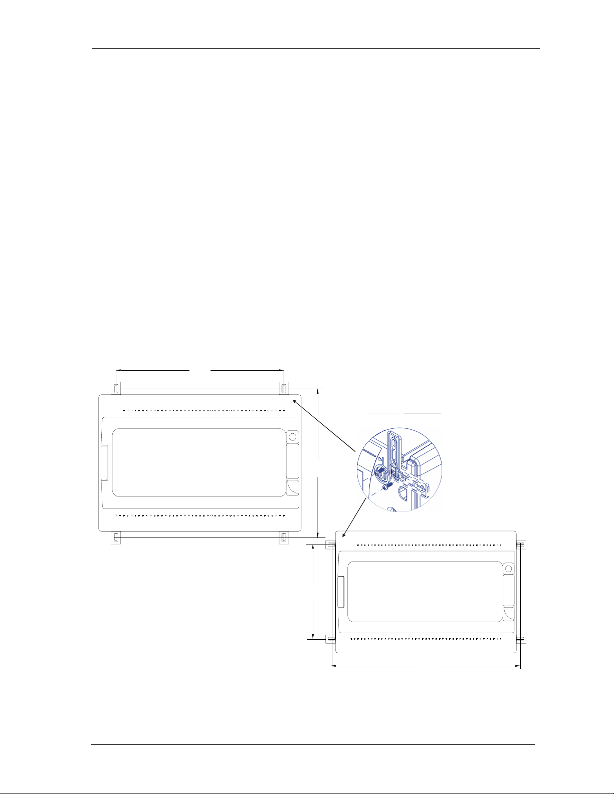
2 INSTALACIÓN 2 INSTALLATION
2.1 Fijación mecánica 2.1 Mechanical fixing
y siga las instrucciones que se detallan a
continuación.
Abra la puerta de la central girando la llave
hasta situarla en la posición
UNLOCK
(desbloqueo).
Desconecte el terminal
CN10
, que conecta la
fuente de alimentación de la placa base al
transformador situado en la parte posterior de la
cabina, y el terminal
CN9
para la conexión de
las baterías. Cierre la puerta y gire la llave a la
posición de cierre
LOCK
(bloqueo).
Desenrosque los cuatro tornillos de la central y
retírelos. Ahora ya puede taladrar la cabina para
permitir la entrada de cable. Recomendamos
que los cables se introduzcan por la parte
inferior de la cabina.
Asegúrese que utiliza un prensaestopas IP65
para garantizar la protección de la entrada de la
cabina.
Fije a la pared la parte posterior de la cabina
mediante los soportes de montaje que se
muestran en la figura siguiente.
strictly follow the instructions detailed here
below.
UNLOCK the control panel front door and open
it.
Disconnect the CN10 terminal, which connects
the power supply wires from the main PCB to the
transformer on the back side of the box, and the
CN9 terminal for the battery connection.
Close the front door and LOCK it again.
Unscrew the four screws placed close to the
panel and remove it.
Now it is possible to drill the rear panel to allow
the cables entrance.
We would recommend having cables entering
from the lower side.
Make sure you are using an adequate IP65
rated cable gland to assure the box ingress
protection is not compromised.
Wall fix the rear panel through the mounting
brackets detailed in the picture.
orificio en la cabina
It is not required to make any
hole in the box
MN-DT-516.doc
(MT3910.doc)
314,00 mm
223,00 mm
13/06/2017 8 de 33
Manual de usuario e instalación
/ Installation and user manual
PL4+
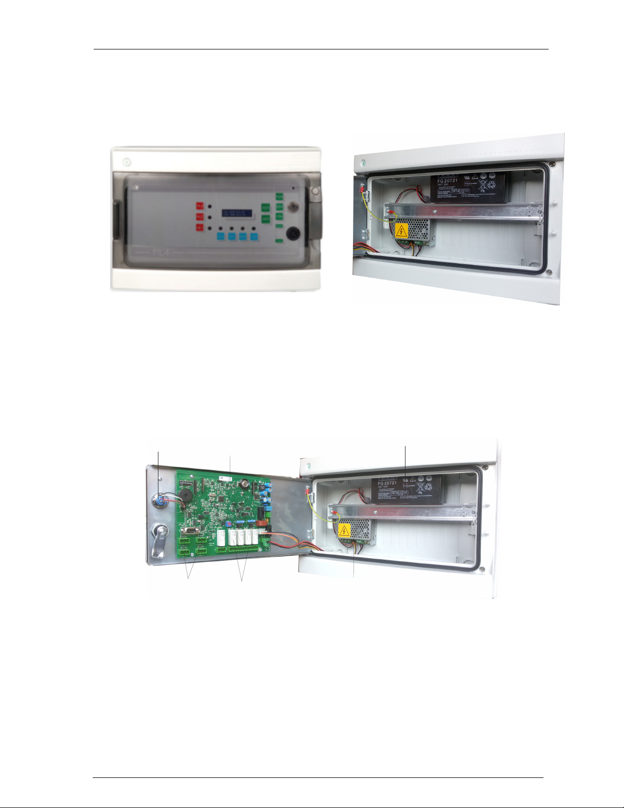
2.2 Diagram and part
2.2 Diagram and part identification
2
Si la instalación requiere la conexión de una
batería de apoyo, coloque la batería en la parte
superior izquierda de la cabina, justo por encima
de la barra metálica, y conecte los cables, tal y
como muestra la figura siguiente.
If the installation requires the connection to a back
up battery, connect the wires to the battery side and
place the battery in the upper left side, just above
the metal bar, as shown in the picture here below.
Coloque y sujete el panel frontal con los 4
tornillos que había retirado anteriormente.
Abra la puerta frontal y conecte de nuevo los
terminales CN10 (alimentación) y JP15 (señales
de control).
Proceda con la conexión de los detectores de
gas tal y como se describe en capítulos
siguientes.
identification
6
4
1-alimentador / power supply
2-bateria 12V 7Ah / battery 12V 7 Ah
3-placa eletronica / main electronic board
3
5
Fasten the front panel by using the 4 screws you
previously removed.
UNLOCK the front door and connect again the
terminals CN10 (power supply) and JP15 (control
signals).
Proceed with the gas detectors connection as
described in the following chapters
1
4-terminales sensor (1-4) / detector (1-4) terminals
5-relés y terminales / relays and terminals
6-llave electrónica / electronic key
MN-DT-516.doc
(MT3910.doc)
13/06/2017 9 de 33
Manual de usuario e instalación
/ Installation and user manual
PL4+
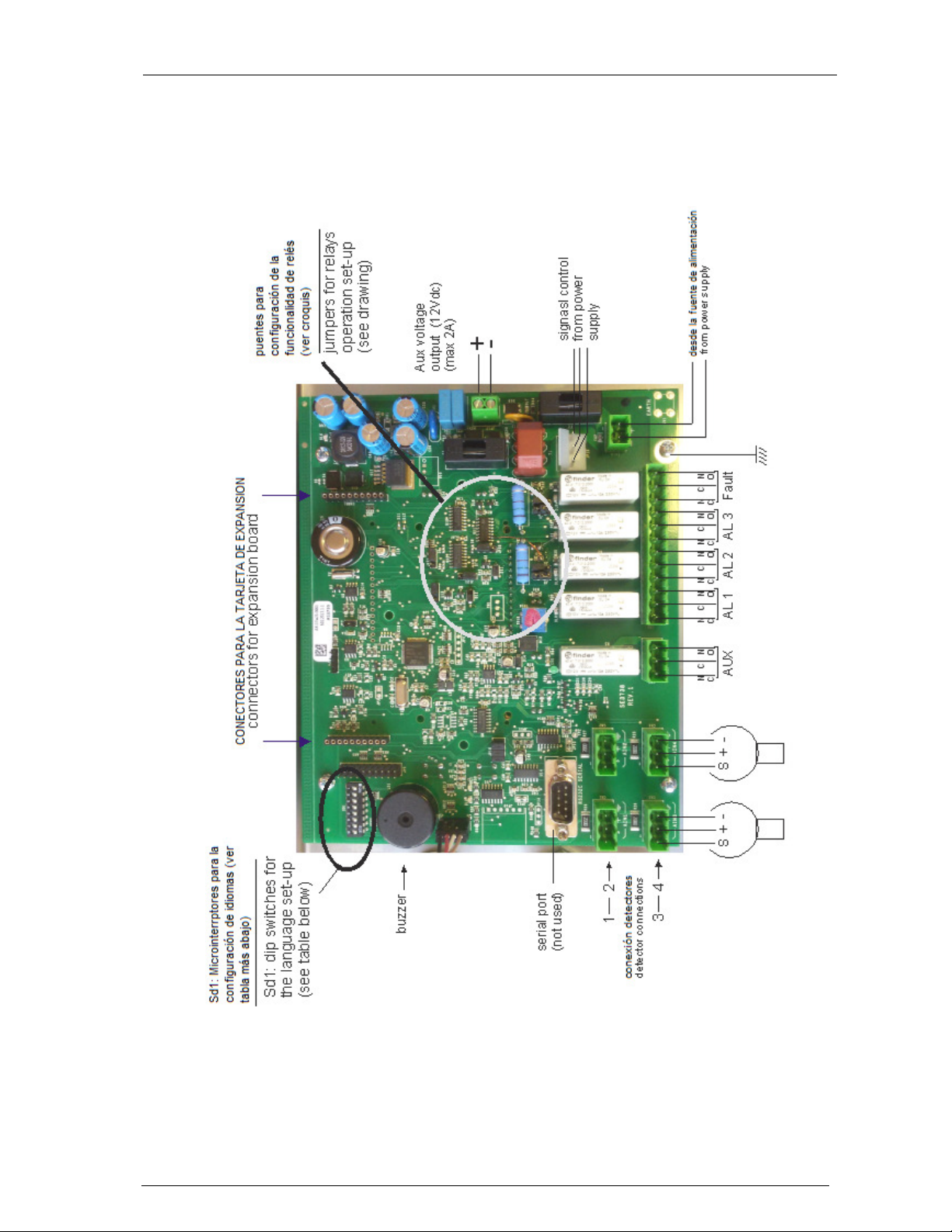
2.3 Equema del circuito base 2.3 Main board layout
La siguiente figura muestra la placa base
montada en la parte posterior de la puerta frontal,
donde se conectará el cableado de los
detectores de gas.
The above figure shows the PCB mounted on
the rear side of the front door, to which gas
detectors are to be connected.
MN-DT-516.doc
(MT3910.doc)
13/06/2017 10 de 33
 Loading...