

Page 1
by Honeywell
Installing the Network Gateway Unit (NGU)Installing the Network Gateway Unit (NGU)
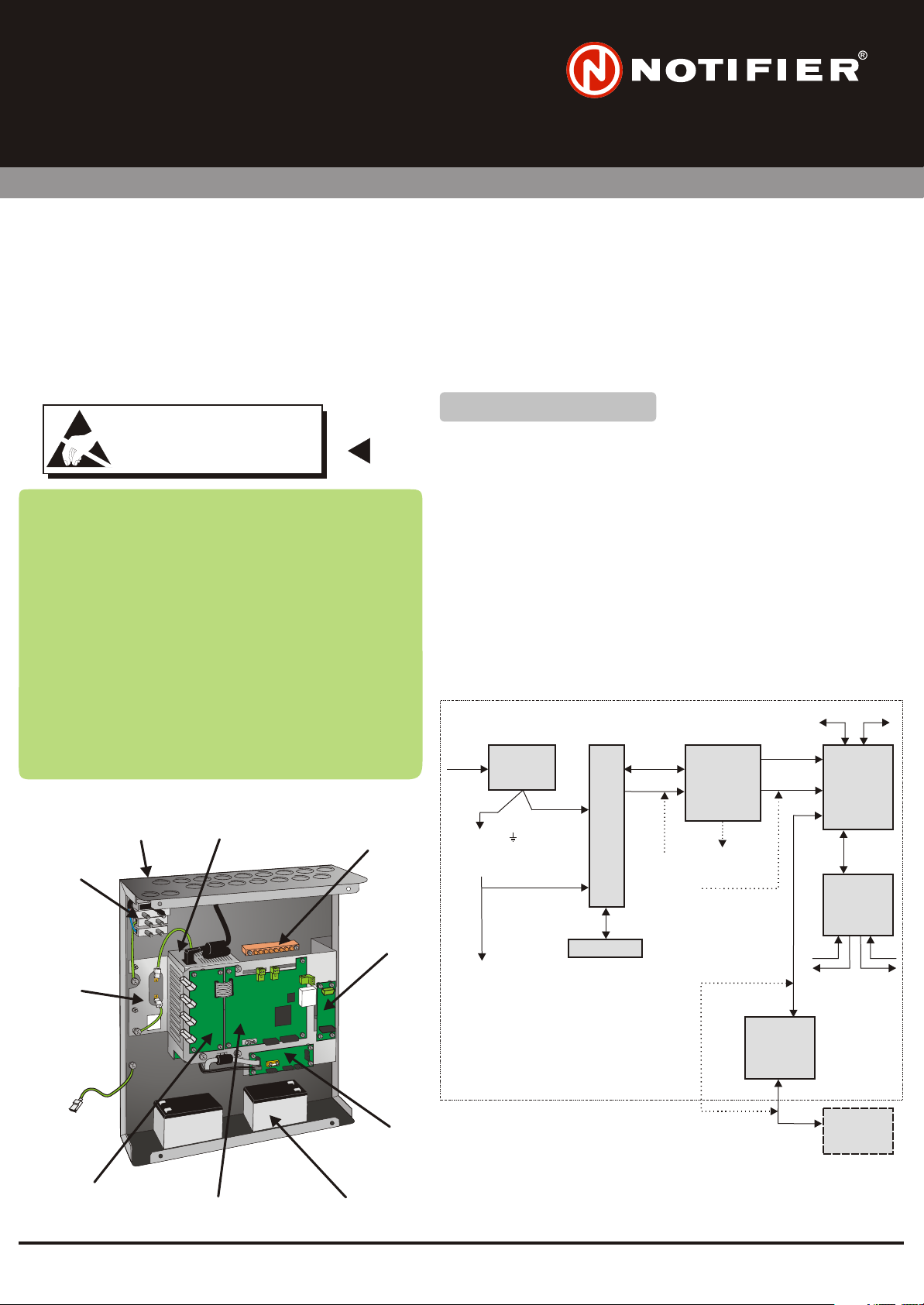
The Network Gateway Unit (PN: 002-467) consists of a Back Box (with cover) with the following fitted on a chassis: a PSU3A
The Network Gateway Unit (PN: 002-467) consists of a Back Box (with cover) with the following fitted on a chassis: a PSU3A
to Network Interface PCB and a Network Gateway Module (NGM) PCB. There is space for a PSU3A and two 12Ah batteries.
to Network Interface PCB and a Network Gateway Module (NGM) PCB. There is space for a PSU3A and two 12Ah batteries.
This basic configuration is used as an ID net Network Booster. The chassis allows a Fibre-optic PCB and RS232 PCB (for
This basic configuration is used as an ID net Network Booster. The chassis allows a Fibre-optic PCB and RS232 PCB (for
connection of a network repeater) to be fitted.
connection of a network repeater) to be fitted.
The PSU3A provides a 28V output and a battery charger. The PSU3A to Network Interface PCB provides battery and PSU
The PSU3A provides a 28V output and a battery charger. The PSU3A to Network Interface PCB provides battery and PSU
fault monitoring, controls the battery charger and converts 28V dc to 5V dc (for the Network PCB). Alternatively, the NGU can
fault monitoring, controls the battery charger and converts 28V dc to 5V dc (for the Network PCB). Alternatively, the NGU can
be powered by an external 28V supply connected at the PSU3A to Network Interface PCB.
be powered by an external 28V supply connected at the PSU3A to Network Interface PCB.
ATTENTIONATTENTION
OBSERVE PRECAUTIONS FOR HANDLING
OBSERVE PRECAUTIONS FOR HANDLING
ELECTROSTATIC SENSITIVE DEVICES
ELECTROSTATIC SENSITIVE DEVICES
Your Network Gateway Unit, PN: 002-467 should contain:
Your Network Gateway Unit, PN: 002-467 should contain:
Back box, NGU, with electronics and cover.
Back box, NGU, with electronics and cover.
Anti-static Warning Instructions PN: 997-180
Anti-static Warning Instructions PN: 997-180
Accessory kit, NGU PN: 020-685
Accessory kit, NGU PN: 020-685
The Accessory kit should contain:
The Accessory kit should contain:
Battery interlink assembly PN: 082-082-002
Battery interlink assembly PN: 082-082-002
Screw M3 x 6mm button head (8 off) PN: 775-059
Screw M3 x 6mm button head (8 off) PN: 775-059
Hex key 2mm PN: 334-051
Hex key 2mm PN: 334-051
Fuse T 2A H 250V (2 off) PN: 570-106
Fuse T 2A H 250V (2 off) PN: 570-106
Fuse T 500mA 250V PN: 570-105
Fuse T 500mA 250V PN: 570-105
Ferrite (5 off) PN: 670-068
Ferrite (5 off) PN: 670-068
Cable tie (1 off) PN: 233-144
Cable tie (1 off) PN: 233-144
NGU EN54-compliant label PN: 345-497 or
NGU EN54-compliant label PN: 345-497 or
Cable Assembly (PSU3A dc power) PN: 082-244
Cable Assembly (PSU3A dc power) PN: 082-244
Cable Assembly (short: NGM/RS232) PN: 082-177-001
Cable Assembly (short: NGM/RS232) PN: 082-177-001
Cable Assembly (x-over: NGM/repeater) PN: 082-255
Cable Assembly (x-over: NGM/repeater) PN: 082-255
PSU3A
PSU3A
(OPTIONAL)
(OPTIONAL)
MAINS
MAINS
TERMINATION
TERMINATION
BLOCK
BLOCK
CHASSISCHASSIS
BACK
BACK
BOX
BOX
2
2
PN: 345-499
PN: 345-499
EARTH
EARTH
TERMINATION
TERMINATION
KIT (OPTIONAL)
KIT (OPTIONAL)
ISOLATED
ISOLATED
RS232 PCB
RS232 PCB
(OPTIONAL)
(OPTIONAL)
Check your equipment....Check your equipment....
Take suitable anti-static precautions, such as wearing a grounded
Take suitable anti-static precautions, such as wearing a grounded
wrist strap, when following ALL instructions. Remove all packaging
wrist strap, when following ALL instructions. Remove all packaging
from the kit and ensure that it has not been damaged in transit (and
from the kit and ensure that it has not been damaged in transit (and
that no items are missing - see checklist on the left) before proceeding
that no items are missing - see checklist on the left) before proceeding
any further. If no damage is evident, proceed using the instructions
any further. If no damage is evident, proceed using the instructions
below. In the unlikely event that damage has occurred or items are
below. In the unlikely event that damage has occurred or items are
missing, DO NOT PROCEED, contact your supplier and refer to the
missing, DO NOT PROCEED, contact your supplier and refer to the
panel’s .
panel’s Installation & Commissioning Manual.
To install the Network Gateway Unit it is necessary to remove the
To install the Network Gateway Unit it is necessary to remove the
supplied electronics chassis (to prevent damage), fit the back box to
supplied electronics chassis (to prevent damage), fit the back box to
the wall, re-install the supplied electronics chassis, and fit any
the wall, re-install the supplied electronics chassis, and fit any
required options. Instructions are given on the following pages.
required options. Instructions are given on the following pages.
Installation & Commissioning Manual
(OPTION)
L, N, E
EARTH TO
BACK BOX
EARTH TO
UNIT COVER,
& EARTH TO
Note:
See Section ‘PSU3A to Network
Interface PCB - if using PSU3A’
for 28V supplies to external
equipment.
MAINS
TERMINAL
BLOCK
SAFETY
EARTH TO
PSU
CHASSIS
L, N
BATTERIES
(OPTION)
PSU
3A
RIBBON
28V DC
28V DC
FROM
EXTERNAL
SOURCE
(OPTION)
PCB -
PSU3A
TO
NETWORK
INTERFACE
28V
5V DC
PSU
FAULT
PCB -
ISOLATED
RS232
(OPTION)
2
ID NET
CH1 CH2
PCB -
NETWORK
(NGM)
RIBBON
PCB -
FIBRE-
OPTIC
(OPTION)
CH2
CH1
RX/TX
RX/TX
2
ID NET
FIBRE-OPTIC
FIBRE-OPTIC
PCB
PCB
(OPTIONAL)
(OPTIONAL)
NETWORK
NETWORK
PCB (NGM)
PCB (NGM)
PSU3A TO
PSU3A TO
NETWORK
NETWORK
INTERFACE
INTERFACE
PCB
PCB
BATTERIES
BATTERIES
(NOT SUPPLIED)
(NOT SUPPLIED)
CROSS-
OVER
RIBBON
(OPTION)
1
997-451, Issue 6 July 2006
REPEATER
RS232
Page 2
FOR CLARITY, INTERNAL EQUIPMENT IS NOT
FOR CLARITY, INTERNAL EQUIPMENT IS NOT
SHOWN.
SHOWN.
33
33
22
33
33
11
Installing the Network Gateway Unit (Continued)
Preparing the Back Box
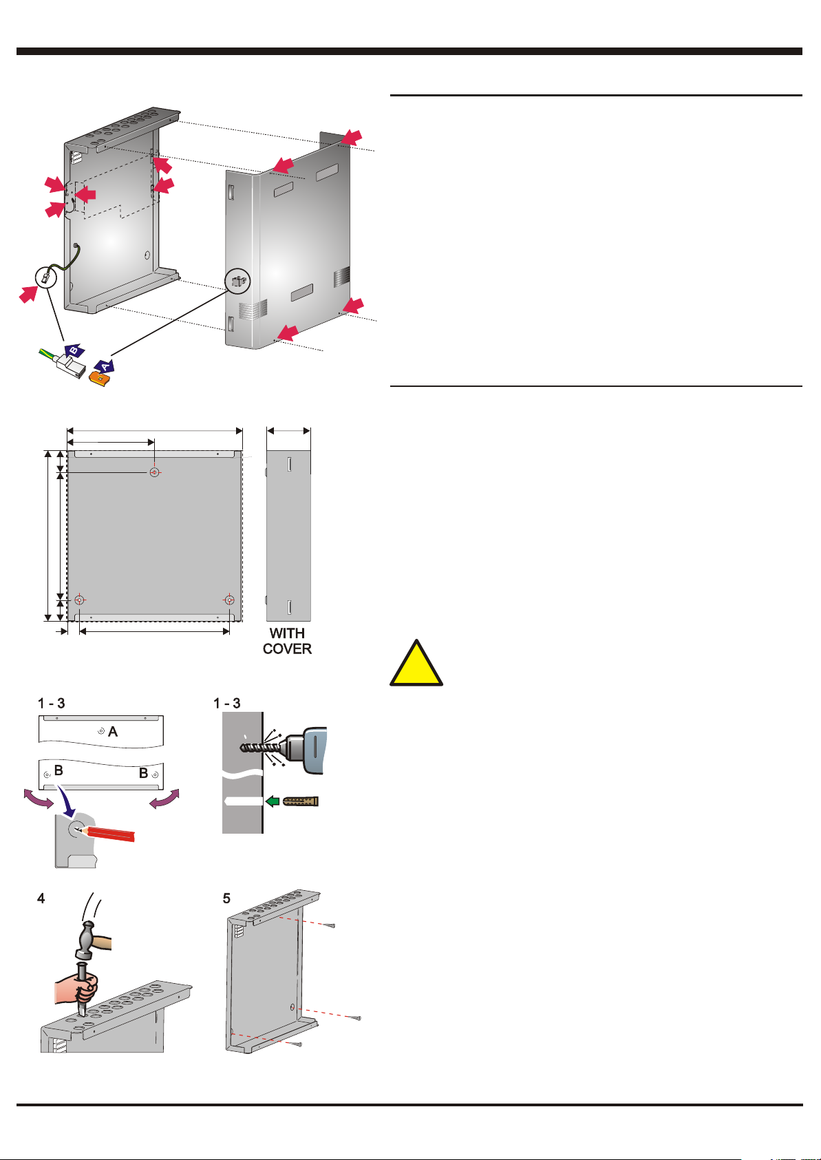
1 Remove and retain the four screws that secure the front cover. Disconnect
1 Remove and retain the four screws that secure the front cover. Disconnect
the cover earth lead from the blade on the cover. Place the cover in a
11
the cover earth lead from the blade on the cover. Place the cover in a
protective bag and store safely.
protective bag and store safely.
2 At the back box, disconnect the chassis earth lead from the blade terminal.
2 At the back box, disconnect the chassis earth lead from the blade terminal.
3 Remove and retain the 4 nuts and washers that secure the chassis to the
3 Remove and retain the 4 nuts and washers that secure the chassis to the
back box, and remove the chassis together with the electronics mounted
back box, and remove the chassis together with the electronics mounted
on it. Place in anti-static bag and store safely.
on it. Place in anti-static bag and store safely.
11
11
11
Note: All blade connections to earth incorporate a locking barb. To make a
Note: All blade connections to earth incorporate a locking barb. To make a
connection push the shrouded receptacle on to the earth blade (A). To
connection push the shrouded receptacle on to the earth blade (A). To
remove this connection, pull the shroud (B), NOT the earth wire.
remove this connection, pull the shroud (B), NOT the earth wire.
Fitting the Back Box to the Wall
Wall Flatness
Wall Flatness
105.00
To prevent distortion, the back box MUST be installed on the wall as flat as
To prevent distortion, the back box MUST be installed on the wall as flat as
possible, i.e. with a maximum flatness deviation between any two points of
possible, i.e. with a maximum flatness deviation between any two points of
3mm. Where the wall is out of tolerance, use appropriate packing pieces when
3mm. Where the wall is out of tolerance, use appropriate packing pieces when
installing the back box to meet the above requirements.
installing the back box to meet the above requirements.
Failure to comply with this requirement will result in the misalignment of
Failure to comply with this requirement will result in the misalignment of
the cover’s securing screws, which may cause difficulties in fitting the
the cover’s securing screws, which may cause difficulties in fitting the
cover.
cover.
All dimensions are in millimeters. Fixing hole diameters are 6mm.
All dimensions are in millimeters. Fixing hole diameters are 6mm.
Procedure
Procedure
When a suitable location has been found for installing the back box, and the
When a suitable location has been found for installing the back box, and the
Network Gateway Module electronics have been removed, fix the back box to
Network Gateway Module electronics have been removed, fix the back box to
the wall as follows:
the wall as follows:
365.00
37.50
190.00
45.00
275.00
45.00
380.00
301.00
DO NOT use the back box as a guide when drilling.DO NOT use the back box as a guide when drilling.
!!
1 Using a suitable-sized drilling bit - for holes to take up to 6mm (No. 12-
1 Using a suitable-sized drilling bit - for holes to take up to 6mm (No. 12-
sized) wood screws - drill a hole at position A in the wall. Fit a suitable-
sized) wood screws - drill a hole at position A in the wall. Fit a suitable-
sized wall-plug, or equivalent.
sized wall-plug, or equivalent.
2 Hold the back box in position at hole A (ensure the panel is level) and mark
2 Hold the back box in position at hole A (ensure the panel is level) and mark
the position of the remaining fixing holes (B). Remove the back box and
the position of the remaining fixing holes (B). Remove the back box and
store safely.
store safely.
3 Drill two holes at positions B in the wall, and fit suitable-sized wall-plugs, or
3 Drill two holes at positions B in the wall, and fit suitable-sized wall-plugs, or
equivalent.
equivalent.
4 Prepare apertures (20mm knockouts) required for cable access. Make
4 Prepare apertures (20mm knockouts) required for cable access. Make
sure paint is scraped from the area surrounding the knockouts, to ensure
sure paint is scraped from the area surrounding the knockouts, to ensure
good earthing for glands, or use earth termination kit 020-453 (see
good earthing for glands, or use earth termination kit 020-453 (see
previous page for mounting position). Use the 2 top front knockouts for
previous page for mounting position). Use the 2 top front knockouts for
fibre-optic cables.
fibre-optic cables.
5 Secure the back box to the wall using all three fixing holes and
5 Secure the back box to the wall using all three fixing holes and
appropriate-sized screws (up to 6mm [No. 12-sized] round or pan-head
appropriate-sized screws (up to 6mm [No. 12-sized] round or pan-head
screws - do not use countersunk screws).
screws - do not use countersunk screws).
6 If a PSU3A is to be fitted, follow the procedure given on the next page.
6 If a PSU3A is to be fitted, follow the procedure given on the next page.
7 Reverse the ‘Preparing the Back Box’ procedure to refit all items except
7 Reverse the ‘Preparing the Back Box’ procedure to refit all items except
the cover. Ensure chassis earth connections are made correctly.
the cover. Ensure chassis earth connections are made correctly.
8 If an RS232 or Fibre-optic PCB is to be fitted, follow the appropriate ‘Fitting
8 If an RS232 or Fibre-optic PCB is to be fitted, follow the appropriate ‘Fitting
Optional PCBs’ procedure given on following pages.
Optional PCBs’ procedure given on following pages.
9 Refit the cover (ensure earth lead is connected).
9 Refit the cover (ensure earth lead is connected).
2
997-451, Issue 6 July 2006
Page 3

GG
HH
XX
(typical 4
(typical 4
locations)
locations)
Installing the Network Gateway Unit (Continued)
Fitting a PSU3A (Kit PN: 020-648) - Optional
DD
C
C
(typical 4
(typical 4
locations)
locations)
E
E
AA
BB
FF
LL
NN
F - in detailF - in detail
JJ
Fitting a PSU3A (Kit PN: 020-648) - Optional
TRANSIT CABLE CLIP: Before proceeding, CAREFULLY cut the cable
TRANSIT CABLE CLIP: Before proceeding, CAREFULLY cut the cable
clip that secures the ferrite cable loop to the chassis (at 'X' on drawing).
clip that secures the ferrite cable loop to the chassis (at 'X' on drawing).
This procedure assumes that the chassis has been removed from the back
This procedure assumes that the chassis has been removed from the back
box - see ‘Preparing the Back Box’.
box - see ‘Preparing the Back Box’.
1
Disconnect the dc connector (A) from the Network Gateway Module
1 Disconnect the dc connector (A) from the Network Gateway Module
(NGM) - (B).
(NGM) - (B).
2
Remove and retain the four M3 X 8 SEM screws (C) that secure the NGM
2 Remove and retain the four M3 X 8 SEM screws (C) that secure the NGM
to the chassis, then remove the NGM and store it safely (take anti-static
to the chassis, then remove the NGM and store it safely (take anti-static
precautions).
precautions).
3
Orientate the PSU3A (D) as shown and secure it to the chassis using the
3 Orientate the PSU3A (D) as shown and secure it to the chassis using the
M4 x 8 SEM screws (E) supplied with the PSU3A.
M4 x 8 SEM screws (E) supplied with the PSU3A.
4
Replace the NGM onto the chassis (by reversing steps 2 and 1 above),
4 Replace the NGM onto the chassis (by reversing steps 2 and 1 above),
then replace the chassis in the back box.
then replace the chassis in the back box. Ensure the chassis earth
connection is remade.
connection is remade.
5
Push the connector of the PSU3A mains cable (F) into the socket on the
5 Push the connector of the PSU3A mains cable (F) into the socket on the
PSU3A [the other end of the mains cable is factory-fitted to the mains
PSU3A [the other end of the mains cable is factory-fitted to the mains
terminal block (G)]. Ensure the mains cable is routed as shown in the
terminal block (G)]. Ensure the mains cable is routed as shown in the
illustration. Pull tight the cable clip at the side of the back box.
illustration. Pull tight the cable clip at the side of the back box.
6
Connect the PSU earth lead (H) to the upper blade on the back box.
6 Connect the PSU earth lead (H) to the upper blade on the back box.
7
Connect the 4-way power cable (I) and 10-way ribbon cable (J) (supplied
7 Connect the 4-way power cable (I) and 10-way ribbon cable (J) (supplied
with the NGU) between the PSU3A and the PSU3A to Network Interface
with the NGU) between the PSU3A and the PSU3A to Network Interface
PCB.
PCB.
8
Use the supplied cable tie to secure the ribbon cable’s ferrite (K) to the tie
8 Use the supplied cable tie to secure the ribbon cable’s ferrite (K) to the tie
point on the chassis.
point on the chassis.
9
Remove and discard the PSU rating label (L) from the chassis.
9 Remove and discard the PSU rating label (L) from the chassis.
10
Remove and discard the NGU product label (M) from the cover. Peel off
10 Remove and discard the NGU product label (M) from the cover. Peel off
the backing from the NGU EN54-compliant label supplied in the NGU
the backing from the NGU EN54-compliant label supplied in the NGU
accessory kit, and attach the label to the cover in place of the removed
accessory kit, and attach the label to the cover in place of the removed
label.
label.
Ensure the chassis earth
LL
KK
II
MAINS
MAINS
WIRES
WIRES
LL
NN
FOR CLARITY, SHOWN WITH
FOR CLARITY, SHOWN WITH
CHASSIS REMOVED
CHASSIS REMOVED
PSU3APSU3A
MM
Wiring Connections - Mains and Safety Earth
Live and Neutral must only be connected if the PSU3A is fitted. The earth
Live and Neutral must only be connected if the PSU3A is fitted. The earth
connection must always be connected. Cables are to be brought into the
connection must always be connected. Cables are to be brought into the
back box using 20mm knockouts and appropriate glands - (refer to the panel’s
back box using 20mm knockouts and appropriate glands - (refer to the panel’s
Installation & Commissioning manual) in accordance with local standards.
Installation & Commissioning manual) in accordance with local standards.
Terminate the mains/earth at the terminal block; connections are labelled.
Terminate the mains/earth at the terminal block; connections are labelled.
Segregate mains wiring from all other wiring.
Segregate mains wiring from all other wiring.
When terminating mains leads, ensure that the earth lead is
When terminating mains leads, ensure that the earth lead is
!!
longer than L and N.
longer than L and N.
L N L N
>25mm
3
997-451, Issue 6 July 2006
Page 4
Battery 1Battery 1
+
-
Installing the Network Gateway Unit (Continued)
Wiring Connections - Batteries
This procedure only applies if the PSU3A is fitted.This procedure only applies if the PSU3A is fitted.
CAUTION - ENERGY HAZARD! NEVER short the battery
CAUTION - ENERGY HAZARD! NEVER short the battery
terminals.
terminals.
!!
Use valve-regulated, lead-acid type12V, 12Ah batteries.
DD
CC
Fuse FP2 T 6.3A H 250VFuse FP2 T 6.3A H 250V
Battery 2Battery 2
-
+
+ -+ -
FF
THERMTHERM
BB
DD
CC
+
AA
EE
Use valve-regulated, lead-acid type12V, 12Ah batteries.
1
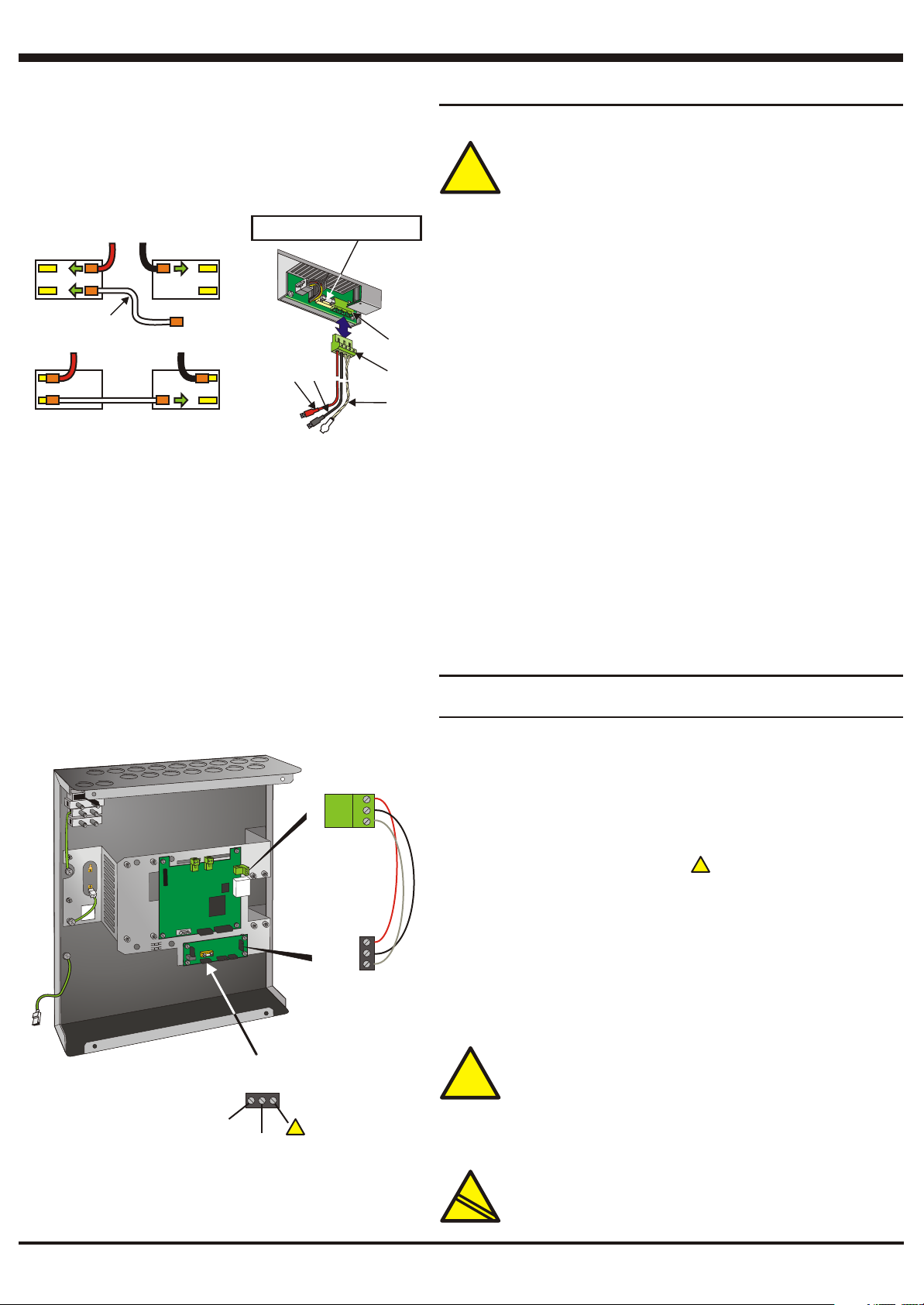
Externally isolate the mains supply at the third-party-supplied isolation
1 Externally isolate the mains supply at the third-party-supplied isolation
unit.
unit.
Connect the battery supply wiring plug (A) to the power socket (B).
2
2 Connect the battery supply wiring plug (A) to the power socket (B).
Place the batteries temporarily in position (with their terminals outermost)
3
3 Place the batteries temporarily in position (with their terminals outermost)
and measure from the PSU’s 4-way output socket to the rear terminal of
and measure from the PSU’s 4-way output socket to the rear terminal of
each battery (i.e. one positive and one negative). Disconnect the leads
each battery (i.e. one positive and one negative). Disconnect the leads
from the output socket. Cut the battery leads supplied to length. Measure
from the output socket. Cut the battery leads supplied to length. Measure
from the socket to a position on the side wall - NOT the top plate - of the
from the socket to a position on the side wall - NOT the top plate - of the
right-hand battery and cut the thermistor lead to length. In both cases
right-hand battery and cut the thermistor lead to length. In both cases
make the leads as short as possible. Reconnect the leads to the socket.
make the leads as short as possible. Reconnect the leads to the socket.
Remove the batteries from the back box.
Remove the batteries from the back box.
Connect the red wire (C) to the positive terminal of battery 2 and the black
4
4 Connect the red wire (C) to the positive terminal of battery 2 and the black
wire (D) to the negative terminal on battery 1.
wire (D) to the negative terminal on battery 1.
Fit the batteries in the back box. Use a suitable silicon-based sealant to
5
5 Fit the batteries in the back box. Use a suitable silicon-based sealant to
secure the thermistor (E) to the side wall - NOT the top plate - of the right
secure the thermistor (E) to the side wall - NOT the top plate - of the right
hand battery.
hand battery.
Connect the interlink cable (F) between battery 1 positive and battery 2
6
6 Connect the interlink cable (F) between battery 1 positive and battery 2
negative terminal. This will power up the NGU, so do this AFTER wiring to
negative terminal. This will power up the NGU, so do this AFTER wiring to
the PCBs has been connected (see following pages).
the PCBs has been connected (see following pages).
When all wiring connections have been completed, fit the cover to the
7
7 When all wiring connections have been completed, fit the cover to the
back box (ensure the interlink cable is not squashed), and then apply
back box (ensure the interlink cable is not squashed), and then apply
power.
power.
28V DC
28V DC
CONNECTOR
CONNECTOR
0V0V
NO
NO
CONNECTION
CONNECTION
REDRED
BLACKBLACK
WHITEWHITE
5V DC
5V DC
CONNECTOR
CONNECTOR
AT NGM
AT NGM
REDRED
BLACKBLACK
WHITEWHITE
5V DC
5V DC
CONNECTOR
CONNECTOR
AT I/F BOARD
AT I/F BOARD
!!
Using an External 28V dc Power Supply - Optional
Using an External 28V dc Power Supply - Optional
The external dc power supply must satisfy the ratings given in the section
The external dc power supply must satisfy the ratings given in the section
‘NGU Electrical Specifications’.
‘NGU Electrical Specifications’. The mains block earth connection must
still be connected to earth
still be connected to earth - see ‘Wiring Connections - Mains and Safety
Earth’ on the previous page.
Earth’ on the previous page.
1
Bring the 28V dc cable into the back box via a 20mm knockout. Route the
1 Bring the 28V dc cable into the back box via a 20mm knockout. Route the
cable behind the chassis, as close as possible to the rear wall of the back
cable behind the chassis, as close as possible to the rear wall of the back
Never route the cable across the front of the NGM.
box.
box. Never route the cable across the front of the NGM.
2
Connect the dc supply to the 0V and terminals of the 28V connector
2 Connect the dc supply to the 0V and terminals of the 28V connector
TB2 on the PSU3A to Network Interface PCB. The use of 1.5mm cable is
TB2 on the PSU3A to Network Interface PCB. The use of 1.5mm cable is
recommended. See EMC requirements warning below.
recommended. See EMC requirements warning below.
3
Remove the white wire (PSU FAULT) between the PSU3A to Network
3 Remove the white wire (PSU FAULT) between the PSU3A to Network
Interface PCB 5V connector TB1 and the NGM 5V connector. Connect the
Interface PCB 5V connector TB1 and the NGM 5V connector. Connect the
fault output from the external supply to the removed connection at the
fault output from the external supply to the removed connection at the
NGM. (Open circuit = fault, Short circuit to 0V = OK). If the external supply
NGM. (Open circuit = fault, Short circuit to 0V = OK). If the external supply
does not have a fault output, jumper between this removed connection
does not have a fault output, jumper between this removed connection
and the black wire (0V) at the NGM.
and the black wire (0V) at the NGM.
EMC requirements: a ferrite (supplied with the NGU) is
EMC requirements: a ferrite (supplied with the NGU) is
required for the dc power input cable and for the fault signal
required for the dc power input cable and for the fault signal
cable. Fit the ferrite directly under the gland at the back box
cable. Fit the ferrite directly under the gland at the back box
!!
knockout. The screen (if plastic glands are used) and all
knockout. The screen (if plastic glands are used) and all
cores (plastic or metal glands) of the cable must pass
cores (plastic or metal glands) of the cable must pass
through the ferrite.
through the ferrite.
The mains block earth connection must
- see ‘Wiring Connections - Mains and Safety
__
__
!!
2
2
E
E
4
N54
N54
!
!
Use of an external dc power supply does not comply with
Use of an external dc power supply does not comply with
EN54 Part 4.
EN54 Part 4.
997-451, Issue 6 July 2006
Page 5
Installing the Network Gateway Unit (Continued)
CONNECTION BETWEEN TWO
CONNECTION BETWEEN TWO
NETWORK PCBs
NETWORK PCBs
Wiring Connections - Network PCB (NGM)
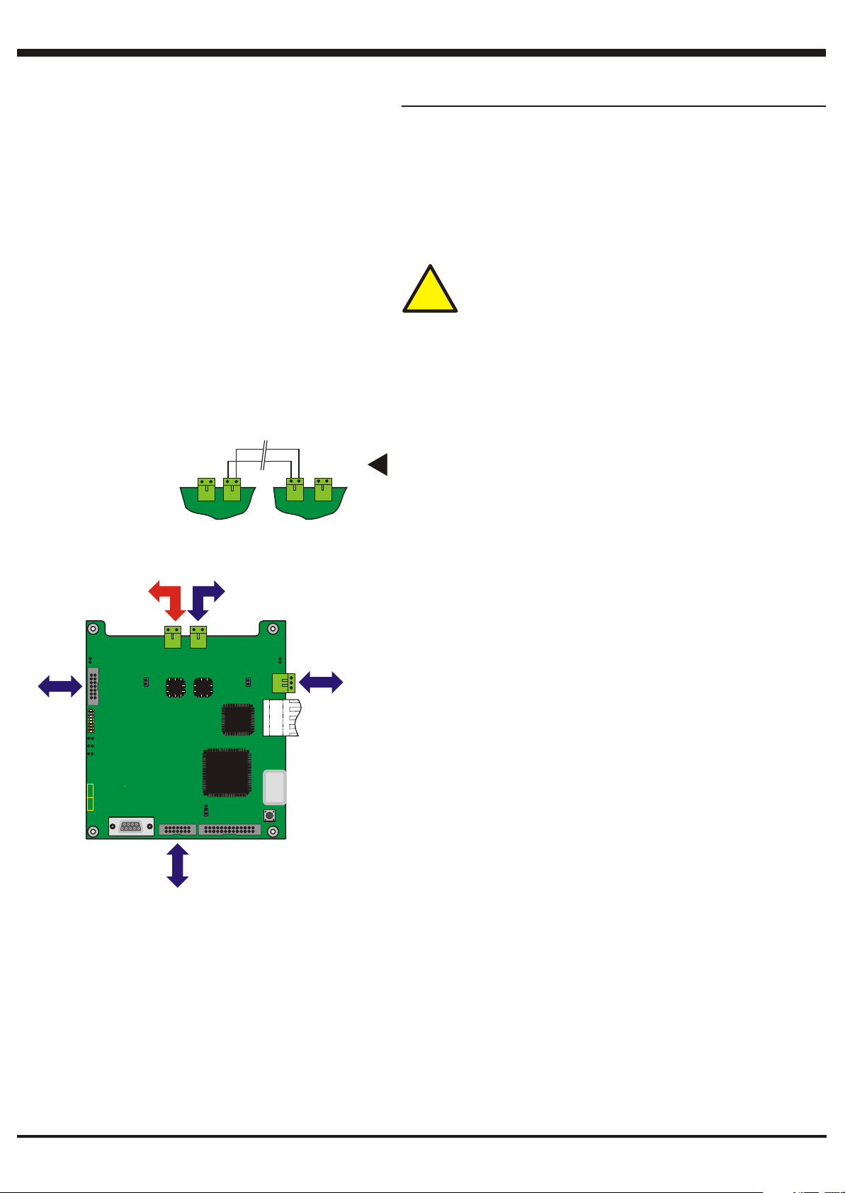
Network cables - Conventional wire cables are terminated at connectors J1
Network cables - Conventional wire cables are terminated at connectors J1
(Channel 1) and J2 (Channel 2). Fibre-optic cable connections are made using
(Channel 1) and J2 (Channel 2). Fibre-optic cable connections are made using
the optional Fibre-optic interface PCB (see following pages).
the optional Fibre-optic interface PCB (see following pages).
Cables are to be brought into the back box using 20mm knockouts and
Cables are to be brought into the back box using 20mm knockouts and
appropriate glands - (refer to the panel’s Installation & Commissioning
appropriate glands - (refer to the panel’s Installation & Commissioning
manual) in accordance with local standards. Cable shields MUST be
manual) in accordance with local standards. Cable shields MUST be
terminated at the gland or back box using the optional earthing blocks (PN:
terminated at the gland or back box using the optional earthing blocks (PN:
020-453).
020-453).
EMC requirements: a ferrite (supplied with the NGU) is
EMC requirements: a ferrite (supplied with the NGU) is
required for each conventional wire network cable. Fit the
required for each conventional wire network cable. Fit the
ferrite directly under the gland at the back box knockout. The
ferrite directly under the gland at the back box knockout. The
!!
screen (if plastic glands are used) and both cores (plastic or
screen (if plastic glands are used) and both cores (plastic or
metal glands) of the cable must pass through the ferrite.
metal glands) of the cable must pass through the ferrite.
Network Comms
J3 To/from
Fibre-optic
PCB
Channel 1
EF1
FO1
FO2
124-312
NETWORK PCB
WO1
Connect terminal A to A and B to B.Connect terminal A to A and B to B.
BB
SW1
AA
J4 DC Power
(pre-wired)
EF2
Jumper Link Setting
Jumper Link Setting
If cables are connected at J1 and/or J2, ensure jumper links are fitted as
If cables are connected at J1 and/or J2, ensure jumper links are fitted as
follows:
follows:
Channel 1 - WO1
Channel 1 - WO1
Channel 2 - WO2
Channel 2 - WO2
When using fibre-optic cables, ensure jumper links are fitted in the following
When using fibre-optic cables, ensure jumper links are fitted in the following
positions instead:
positions instead:
Channel 1 - FO1
Channel 1 - FO1
Channel 2 - FO2
Channel 2 - FO2
For further details refer to the Fibre-optic PCB installation instructions.Note:
Note: For further details refer to the Fibre-optic PCB installation instructions.
Earth Fault Monitoring (EFM)
Earth Fault Monitoring (EFM)
No action needs to be taken at the NGU as EFM must be set at the
No action needs to be taken at the NGU as EFM must be set at the
adjacent panels. Ensure that jumper links JP1 and JP2 are NOT fitted.
adjacent panels. Ensure that jumper links JP1 and JP2 are NOT fitted.
Note: If an external dc power supply is used, and the external supply has its
Note: If an external dc power supply is used, and the external supply has its
0V connected to mains earth, the earth fault monitoring circuit will detect a
0V connected to mains earth, the earth fault monitoring circuit will detect a
fault.
fault.
AA
BB
Channel 2
Network Comms
J1J1
J2J2
WO2
J6 RS232 connection:
to Isolated RS232 Board
(using direct ribbon cable)
or to IDR-6A repeater
(using cross-over ribbon cable)
5
997-451, Issue 6 July 2006
Page 6
Installing the Network Gateway Unit (Continued)
SERIAL No.
PSU/CHGR FLT
SK1
BATT
FLT
PWR
28V IN
ON
SK2
28V
0V
500mA
DO NOT USE
DO NOT USE
CONNECTION
CONNECTION
MARKED __
MARKED __
NOTE - If short circuit isolation is not
required, loop output + should be wired
to terminal 5 and not 2. Terminal 5 is
internally connected to terminal 4.
-
LOOP OUT
+
-
LOOP IN
+
SEE NOTE
+
CHGR INHIB
From
panel/device
CHGR INHIB
!!
+
TB4
TB4
F1
TB2
!!
NOTE - Break
both tabs (J1
COM
FAULT
TB3
N/O COM N/C CHGR INHIB
12
3
4
5
M701
6
7
8910
4
5
1112
3
6
2
7
1
8
0
9
x10
A B C
-
+
CMX
-2E
1 (-)
2 (+)
3 (-)
4 (+)
and J2)
9 (+)
8 (-)
7 (-)
6 (+)
device
5
JP3
JP1
3
2
1
To
Wiring Connections - PSU3A to Network Interface
TB1
PARK
+5V
JP4
JP2
124 - 338
+5V
0V
FLT
0V
PARK
CHGR.
INHIB
TB4
A B
1
0
4
5
6
7
8
0
9
x1
PCB - if using PSU3A
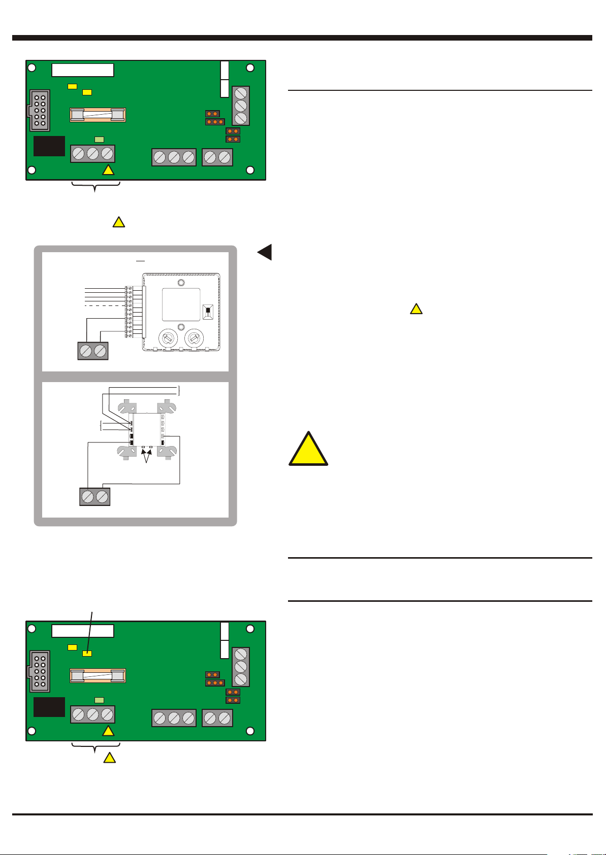
SK1 is used with the PSU3A (ribbon connector).
SK1 is used with the PSU3A (ribbon connector).
SK2 is used with the PSU3A (four-wire dc output connector).
SK2 is used with the PSU3A (four-wire dc output connector).
TB1 is pre-wired to the Network PCB (5V dc supply and fault signal).
TB1 is pre-wired to the Network PCB (5V dc supply and fault signal).
TB2 provides either a 500mA or 2A dc power output -
TB2 provides either a 500mA or 2A dc power output - the latter is only
available for limited periods, e.g. during alarm
available for limited periods, e.g. during alarm. To use the 500mA supply,
simply connect to the 0V and 28V 500mA contacts - this supply is suitable for a
simply connect to the 0V and 28V 500mA contacts - this supply is suitable for a
repeater. To use the 2A supply, proceed as follows:
repeater. To use the 2A supply, proceed as follows:
i Remove fuse F1 and replace with one of the supplied T 2A H 250V fuses.
i Remove fuse F1 and replace with one of the supplied T 2A H 250V fuses.
ii Connect to the 0V and 28V 500mA contacts.
ii Connect to the 0V and 28V 500mA contacts. The supply cannot charge
the batteries while delivering 2A,
the batteries while delivering 2A, so you must temporarily inhibit the
charger by joining together both contacts of TB4 (see examples opposite
charger by joining together both contacts of TB4 (see examples opposite
- remember to add the control module to the control matrix!).
- remember to add the control module to the control matrix!). Whenever
the charger is inhibited there will be no charge replenishment to the
the charger is inhibited there will be no charge replenishment to the
batteries. The charger inhibit link must be at JP4 (PARK) NOT JP2
batteries. The charger inhibit link must be at JP4 (PARK) NOT JP2
(CHRG INHIB) - if charging is permanently inhibited the batteries
(CHRG INHIB) - if charging is permanently inhibited the batteries
will discharge resulting in a battery fault message at the fire panel.
will discharge resulting in a battery fault message at the fire panel.
Never
use the terminal marked __ as an output.
Never use the terminal marked __ as an output.
TB3 is a common fault output. The relay de-energises if there is a PSU or
TB3 is a common fault output. The relay de-energises if there is a PSU or
battery fault. With link JP3 fitted (PARK position) the output takes the form of
battery fault. With link JP3 fitted (PARK position) the output takes the form of
volt-free contacts rated at 30Vdc, 1A (resistive load). With the link removed
volt-free contacts rated at 30Vdc, 1A (resistive load). With the link removed
from JP3 and fitted to the ‘+5V’ position, the common contact is taken to 5V dc
from JP3 and fitted to the ‘+5V’ position, the common contact is taken to 5V dc
via a 1k resistor. With the link removed from JP3 and fitted to the ‘0V’ position,
via a 1k resistor. With the link removed from JP3 and fitted to the ‘0V’ position,
the common contact is taken to 0V via a 1k resistor.
the common contact is taken to 0V via a 1k resistor.
TB4 allows application of an external charger inhibit signal as described
TB4 allows application of an external charger inhibit signal as described
above.
above.
EMC requirements: a ferrite (supplied with the NGU) is
EMC requirements: a ferrite (supplied with the NGU) is
required for the dc power output cable, for the fault signal
required for the dc power output cable, for the fault signal
cable, and for the remote charger inhibit signal cable. Fit the
cable, and for the remote charger inhibit signal cable. Fit the
!!
ferrite directly under the gland at the back box knockout.
ferrite directly under the gland at the back box knockout.
The screen (if plastic glands are used) and all cores (plastic
The screen (if plastic glands are used) and all cores (plastic
or metal glands) of the cable must pass through the ferrite.
or metal glands) of the cable must pass through the ferrite.
Jumper Link Setting
Jumper Link Setting
JP1 and JP3 are used in conjunction with TB3 as described above.
JP1 and JP3 are used in conjunction with TB3 as described above.
JP2 is used to permanently inhibit the charger. JP4 is used if the charger is not
JP2 is used to permanently inhibit the charger. JP4 is used if the charger is not
to be inhibited. Always place link on JP4. See the description of TB2 above.
to be inhibited. Always place link on JP4. See the description of TB2 above.
!!
so you must temporarily inhibit the
. To use the 500mA supply,
The supply cannot charge
the latter is only
Whenever
IGNORE THIS LED
IGNORE THIS LED
WHEN USING AN
WHEN USING AN
EXTERNAL POWER
EXTERNAL POWER
SUPPLY
SUPPLY
SERIAL No.
PSU/CHGR FLT
SK1
28V IN
SK2
0V
CONNECTIONS
CONNECTIONS
USED WITH
USED WITH
EXTERNAL PSU
EXTERNAL PSU
BATT
FLT
PWR
ON
28V
500mA
0V & __
0V & __
Wiring Connections - PSU3A to Network Interface
PCB - if using External Power Supply
TB1 is pre-wired to the Network PCB (5V dc supply and fault signal). This
TB1 is pre-wired to the Network PCB (5V dc supply and fault signal). This
connector will require re-wiring as described in the Section ‘Using an External
connector will require re-wiring as described in the Section ‘Using an External
28V Power Supply - Optional’.
TB1
124 - 338
PARK
JP3
JP1
TB3
+5V
JP4
JP2
F1
COM
FAULT
TB2
!!
!!
N/O COM N/C CHGR INHIB
0V
TB4
PARK
CHGR.
INHIB
+5V
0V
FLT
28V Power Supply - Optional’.
TB2 is used as described in the Section ‘Using an External 28V dc Power
TB2 is used as described in the Section ‘Using an External 28V dc Power
Supply - Optional’.
Supply - Optional’.
SK1, SK2, TB3 and TB4 are not used in this application. Do not make any
SK1, SK2, TB3 and TB4 are not used in this application. Do not make any
connections.
connections.
Jumper Link Setting
Jumper Link Setting
In this application, links should be placed on JP3 and JP4. Do not place links
In this application, links should be placed on JP3 and JP4. Do not place links
on JP1 and JP2.
on JP1 and JP2.
6
997-451, Issue 6 July 2006
Page 7
Installing the Network Gateway Unit (Continued)
Fitting Optional PCBs
CAUTION - Isolate mains and battery power or external
CAUTION - Isolate mains and battery power or external
power before installing or removing the optional PCB.
power before installing or removing the optional PCB.
!!
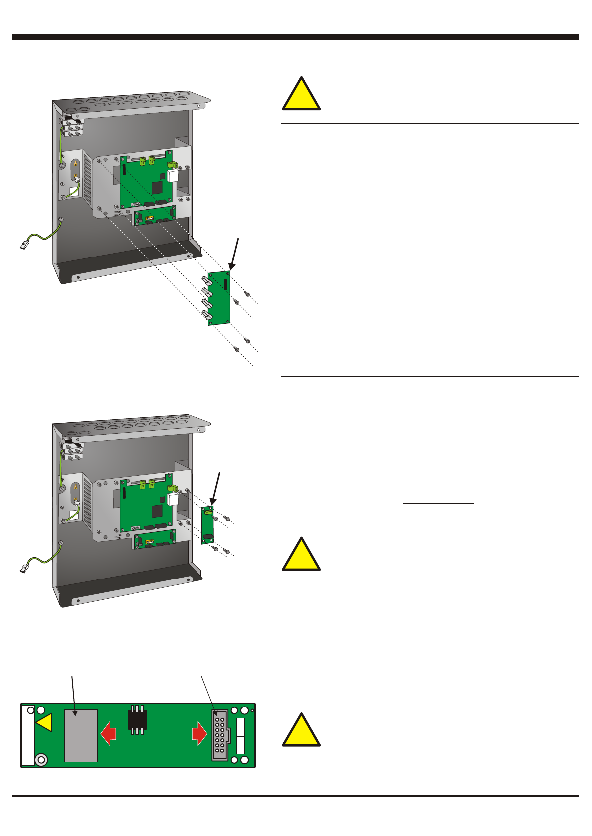
Fibre-Optic PCB (Kit PN: 020-643, PCB PN: 124-319)
Fibre-Optic PCB (Kit PN: 020-643, PCB PN: 124-319)
1 Position the Fibre-Optic Board (A) as shown and secure it to the chassis
1 Position the Fibre-Optic Board (A) as shown and secure it to the chassis
using the four M3 x 8 SEM screws (B) supplied with the PCB.
using the four M3 x 8 SEM screws (B) supplied with the PCB.
2 Fit the cables and wiring and configure jumper links as described in the
2 Fit the cables and wiring and configure jumper links as described in the
instructions supplied with the PCB.
instructions supplied with the PCB.
AA
Note: Cables are to be brought into the back box using the top front two
Note: Cables are to be brought into the back box using the top front two
20mm knockouts and appropriate glands. Ensure that the bend radius
20mm knockouts and appropriate glands. Ensure that the bend radius
of the fibre-optic cable is within the limit specified for the cable type
of the fibre-optic cable is within the limit specified for the cable type
being used.
being used.
B x 4B x 4
AA
B x 4B x 4
Isolated RS232 PCB (Kit PN: 020-478, PCB PN: 124-300)
Isolated RS232 PCB (Kit PN: 020-478, PCB PN: 124-300)
1 Position the Isolated RS232 Board (A) as shown and secure it to the
1 Position the Isolated RS232 Board (A) as shown and secure it to the
chassis using the four M3 x 8 SEM screws (B) supplied with the PCB. The
chassis using the four M3 x 8 SEM screws (B) supplied with the PCB. The
spacers supplied with the PCB are not required and can be discarded.
spacers supplied with the PCB are not required and can be discarded.
2 Connect the wiring (see drawing below). Use the straight ribbon cable
2 Connect the wiring (see drawing below). Use the straight ribbon cable
(NOT the cross-over cable) supplied with the NGU to connect to the
(NOT the cross-over cable) supplied with the NGU to connect to the
RS232 port on the NGM. : use screened multi-core
RS232 port on the NGM. Network repeater: use screened multi-core
cable to connect SK1 on the NGU's Isolated RS232 PCB to connector
cable to connect SK1 on the NGU's Isolated RS232 PCB to connector
SK1 on the Isolated RS232 PCB in the repeater.
SK1 on the Isolated RS232 PCB in the repeater.
EMC requirements: a ferrite (supplied with the NGU) is
EMC requirements: a ferrite (supplied with the NGU) is
required for the RS232 cable. Fit the ferrite directly above
required for the RS232 cable. Fit the ferrite directly above
the back box knockout. The screen and all cores of the cable
the back box knockout. The screen and all cores of the cable
!!
must pass through the ferrite.
must pass through the ferrite.
Network repeater
TWO-PART
TWO-PART
CONNECTOR, TO
CONNECTOR, TO
EXTERNAL EQUIPMENT
EXTERNAL EQUIPMENT
RTS
!!
Rx
CTS
S/No.
Tx
SIG
OV
SK1
22
SK1SK1 SK2SK2
CONNECTION
CONNECTION
TO NETWORK
TO NETWORK
PCB (NGM)
PCB (NGM)
SK2
22
CAUTION: Equipment connected to this RS232 port must be
CAUTION: Equipment connected to this RS232 port must be
suitably protected against electric shock. Voltages on the
suitably protected against electric shock. Voltages on the
interconnections must not exceed 42V peak or 60V dc under
interconnections must not exceed 42V peak or 60V dc under
!!
normal or single fault conditions.
124 - 300
7
normal or single fault conditions.
997-451, Issue 6 July 2006
Page 8
Installing the Network Gateway Unit (Continued)
Connecting an IDR-6A Network Repeater
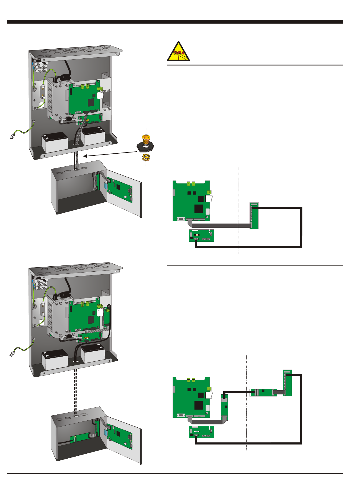
To achieve the transmission path integrity required by EN54-2:
To achieve the transmission path integrity required by EN54-2:
12.5.3, the repeater and NGU must be physically connected as
12.5.3, the repeater and NGU must be physically connected as
shown opposite to create a single enclosure.
shown opposite to create a single enclosure.
1 Prepare one knockout at the top of the repeater and one knockout at the
1 Prepare one knockout at the top of the repeater and one knockout at the
base of the NGU.
base of the NGU.
2 Install the NGU and repeater with the repeater directly below the NGU and
2 Install the NGU and repeater with the repeater directly below the NGU and
with the prepared knockouts aligned.
with the prepared knockouts aligned.
3 Connect the repeater and NGU using a suitable short coupling through
3 Connect the repeater and NGU using a suitable short coupling through
the knockouts.
the knockouts.
4 Route the cross-over ribbon cable (supplied with the NGU) through the
4 Route the cross-over ribbon cable (supplied with the NGU) through the
coupling. Connect one end to the RS232 connector on the NGM and the
COUPLINGCOUPLING
coupling. Connect one end to the RS232 connector on the NGM and the
other end to the RS232 connector on the repeater's termination board. A
other end to the RS232 connector on the repeater's termination board. A
ferrite is required immediately above the coupling.
ferrite is required immediately above the coupling.
5 Route the dc power wiring to the repeater through the coupling (use the
5 Route the dc power wiring to the repeater through the coupling (use the
NGU's 500mA output).
NGU's 500mA output).
NGU - SEE NGM
AND PSU3A TO NETWORK INTERFACE
PCB PROCEDURES
NGM
PSU
INTERFACE
PCB
CROSS-OVER RIBBON
NGU TO IDR-6A REPEATER INTERCONNECTIONS
REPEATER - SEE 997-411
SECTION 2.8 FOR DETAILED
WIRING INFORMATION
TERMINATION
PCB
DC POWER CONNECTION
NON-COMPLIANT LONGER-RUN CONNECTION
1 Prepare one knockout at the top of the repeater and one knockout at the
1 Prepare one knockout at the top of the repeater and one knockout at the
NGU (illustration shows the base, but a top knockout can be used).
NGU (illustration shows the base, but a top knockout can be used).
2 Install Isolated RS232 Boards in the repeater and NGU. Route the wiring
2 Install Isolated RS232 Boards in the repeater and NGU. Route the wiring
(max. 15m) between them through the knockouts (CTS and RTS are not
(max. 15m) between them through the knockouts (CTS and RTS are not
needed). A ferrite is required immediately adjacent to the knockout.
needed). A ferrite is required immediately adjacent to the knockout.
3 Route the dc power wiring to the repeater through the knockouts (use the
3 Route the dc power wiring to the repeater through the knockouts (use the
NGU's 500mA output).
NGU's 500mA output).
Use appropriate glands on all knockouts.
Use appropriate glands on all knockouts.
NGU - SEE ISOLATED RS232 PCB
AND PSU3A TO NETWORK INTERFACE
PCB PROCEDURES
NGM
PSU
INTERFACE
PCB
RIBBON
NGU TO IDR-6A REPEATER INTERCONNECTIONS
8
RS232 LINK
ISOLATED
RS232 PCB
REPEATER - SEE 997-411
SECTION 2.8 FOR DETAILED
WIRING INFORMATION
RIBBON
ISOLATED
RS232 PCB
DC POWER CONNECTION
TERMINATION
PCB
997-451, Issue 6 July 2006
Page 9

Installing the Network Gateway Unit (Continued)
NGU Electrical Specifications
NGU Electrical Specifications
Input Rating when used with external PSU:
Input Rating when used with external PSU:
Input voltage: 22V - 28Vdc
Input voltage: 22V - 28Vdc
Maximum current consumption: 100mA
Maximum current consumption: 100mA
Input Rating when used with PSU3A:
Input Rating when used with PSU3A:
Voltage, frequency: 230Vac, ±15%, 50/60Hz
Voltage, frequency: 230Vac, ±15%, 50/60Hz
Maximum current consumption: 1.6A (Protection by 2A mains supply fuse in terminal block)
Maximum current consumption: 1.6A (Protection by 2A mains supply fuse in terminal block)
Output Rating when used with PSU3A:
Output Rating when used with PSU3A:
Output voltage: 26V - 28Vdc
Output voltage: 26V - 28Vdc
Maximum output current: 500mA (with battery charger available) or 2A (without
Maximum output current: 500mA (with battery charger available) or 2A (without
battery charger), dependent upon the fuse fitted
battery charger), dependent upon the fuse fitted
Battery Charger Output Ratings (PSU3A):
Battery Charger Output Ratings (PSU3A):
Battery voltage when charged: 27.3V at 20°C (Charge float voltage)
Battery voltage when charged: 27.3V at 20°C (Charge float voltage)
Temperature compensation: -3mV/°C/cell
Temperature compensation: -3mV/°C/cell
Battery fuse rating: T 6.3A H 250V
Battery fuse rating: T 6.3A H 250V
Final end battery voltage: 21V
Final end battery voltage: 21V
Charger ripple voltage: 140mV RMS
Charger ripple voltage: 140mV RMS
Low Voltage Shut Down
Low Voltage Shut Down
If the battery voltage drops below 21V, then the batteries are disconnected automatically to avoid system
If the battery voltage drops below 21V, then the batteries are disconnected automatically to avoid system
malfunction and deep discharge causing permanent damage. Battery capacity should be selected to ensure
malfunction and deep discharge causing permanent damage. Battery capacity should be selected to ensure
sufficient backup time in the event of mains power failure.
sufficient backup time in the event of mains power failure.
Battery Capacity
Battery Capacity
Sealed valve regulated lead-acid battery types MUST be used. Battery lifetime depends on the ambient
Sealed valve regulated lead-acid battery types MUST be used. Battery lifetime depends on the ambient
temperature. Refer to the battery manufacturer's technical specification for guidance. When using multiple
temperature. Refer to the battery manufacturer's technical specification for guidance. When using multiple
batteries, all batteries should be from the same Manufacturer, of the same type and date code and be mounted
batteries, all batteries should be from the same Manufacturer, of the same type and date code and be mounted
in the same cabinet.
in the same cabinet.
Two 12V batteries must be connected in series.
Two 12V batteries must be connected in series.
9
997-451, Issue 6 July 2006
 Loading...