

Page 1
2
1
3
0
4
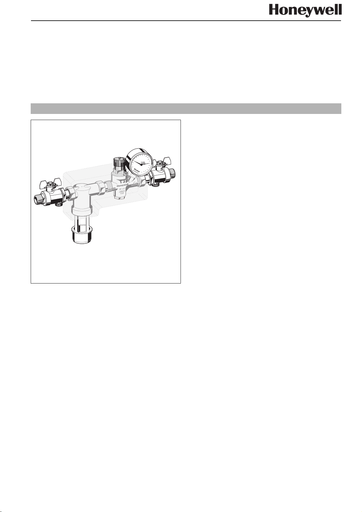
Construction
The refilling combination consists of:
• Ball valve, up- and downstream
• Complete backflow preventer with discharge connection,
valve cartridge (incl. integrated non return valve and discharge valve, upstream), integrated strainer upstream
(mesh size approx. 0,5 mm) and non return valve
downstream
• Complete pressure reducing valve (incl. diaphragm, valve
seat, adjustment spring, spring hood and adjuster knob)
and manometer
Materials
• Housing in dezincification-resistant brass
• Discharge connection in high-grade synthetic material
• Valve cartridge in high-grade synthetic material
• Non return valve in high-grade synthetic material
• Spring hood in high-grade synthetic material
• Diaphragm in NBR, fibre-reinforced
• Adjustment spring in spring steel
• Seals in NBR and EPDM
• Insulation jacket in EPP
NK295S
Refilling combination
Compact construction
Product specification sheet
Application
The refilling combination serves automatic filling and refilling
from closed heating systems to DIN EN 12828:2003.
The refilling combination can be connected in accordance to
DIN EN 1717 constantly with the drinking water supply.
The refilling combination combines backflow preventer, pressure reducing valve and ball valve in one appliance.
The refilling combination contains all devices for refilling a heating installation, according to conforming standards.
Special Features
• compact construction
• constant connection with the drinking water supply in accordance with DIN EN1717 by hose line or piping are possible
• corrosion resistant by use of brass and stainless steel
• low flow resistance and high rate of flow
• optimal protection of the drinking water supply
• backflow preventer offers threefold security - two non return
valve and a discharge valve separate the backflow preventer into three chambers
• field-tested reliable pressure reducing valve
• pressure reducing valve with inlet pressure balancing - inlet
pressure fluctuation does not influence the outlet pressure
• outlet pressure adjustable at the adjuster knob (outlet pressure is set to 1,5 bar during manufacture)
• non return valve DIN/DVGW-approved
• variable connection options to the heating system
• reliable and tested
• low maintenance effort
• complies with KTW requirements
Range of Application
Medium Water without inhibitors
Inlet pressure min. 1,5 bar
max. 10,0 bar
Outlet pressure 1,5-6 bar
Liquid category
Backflow Preventer
Technical Data
Installation position horizontal pipework with discharge
Operating temperature max. 65°C
Connection size
Discharge
Connection sizes 1/2" AG
3 (slightly toxic materials)
connection directed downwards
HT 40
Honeywell GmbH • Subject to change 1 EN0H-1230GE23 R0405
Page 2
Refilling Combination NK295S
ø
40mm
l
3
l
2
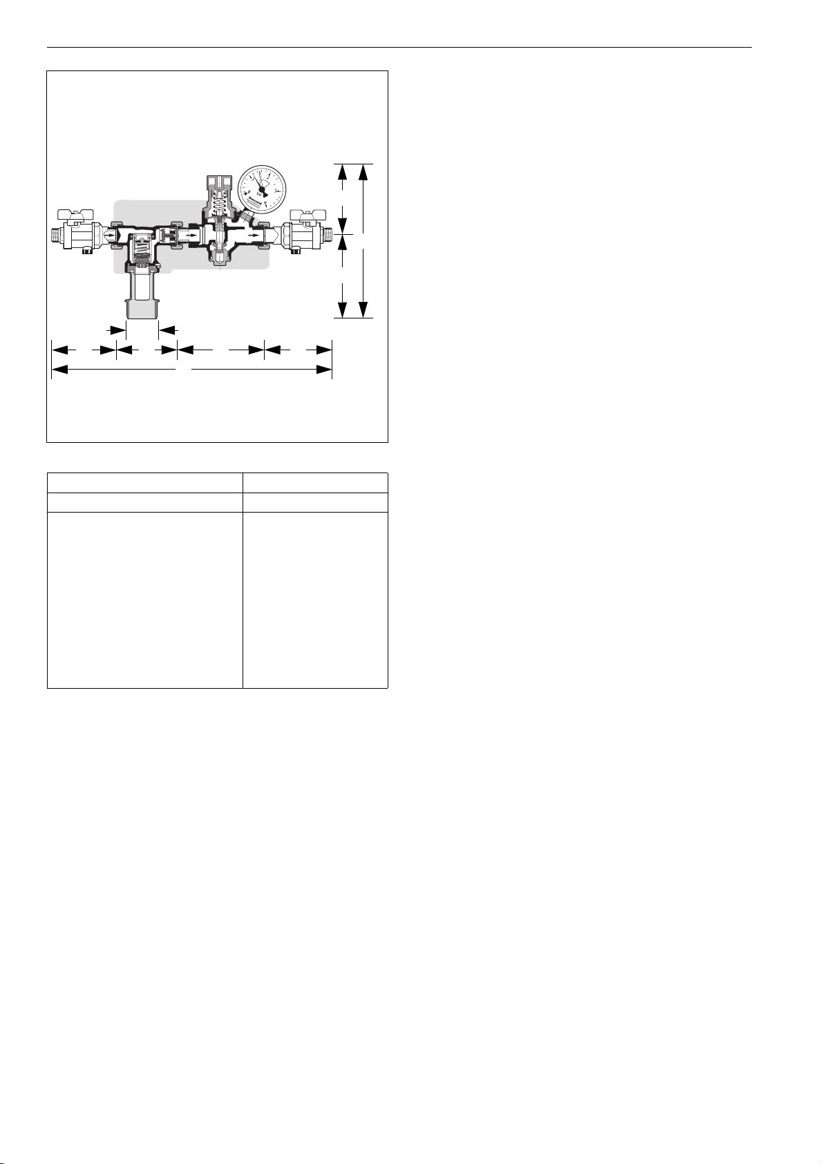
Connection size R 1/2"
Weight ca. kg 1,6
Dimensions mm
l
1
l
4
L
H188,5
h
1
h
2
67,5
121
L389
l
1
l
2
l
3
l
4
104
85
100
100
Functional description
The refilling combination combines backflow preventer, pressure reducing valve and ball valve in one appliance.
The backflow preventer is a safety device in accordance with
DIN EN 1717 to protect systems against back pressure, back
flow and back syphonage of non-potable water into service
pipe, plants and equipments.
h
1
The backflow preventer is separated in three chambers (inlet,
middle and outlet chamber).
If no water is drawn from the downstream system, the backflow
H
preventer is in normal position. The up- and downstream non
return valves and the discharge valve are closed.
h
2
If water is drawn from the downstream system, the backflow
preventer is in flow position. The non return valves up- and
downstream are opened and the discharge valve is closed.
The backflow preventer change to shut-off position (back pressure) if the differential pressure between middle- and inlet
chamber is smaller than 10% of the inlet pressure. The
upstream non return valve is closed and the discharge valve is
opened.
There is no possibility to control the safety function by
measuring.
The pressure reducing valve reduces the pressure on the inlet
side (admission pressure) to the level of the desired pressure
on the outlet side (outlet pressure) in individual cases.
The pressure reducing valve functions on a force equalisation
principle. The force of a diaphragm operates against the spring
force of the regulating valve. If the outlet pressure and therefore diaphragm force fall because water is drawn, then the
greater force of the spring causes the valve to open. The outlet
pressure then increases until the forces between the diaphragm and the spring are equal again.
The inlet pressure (admission pressure) has no influence on
the regulating valve of the pressure reducing valve. Inlet pressure fluctuation does not influence the outlet pressure, thus
providing inlet pressure balancing.
Designs
NK295S-1/2A = Standard version with threaded connection
R1/2"
EN0H-1230GE23 R0405 2 Honeywell GmbH • Subject to change
Page 3

Installation Example
Refilling Combination NK295S
Installation Guidelines
• Install in horizontal pipework with discharge connection directed downwards.
• The installation may not take place in areas or ducts where
poisonous gases or vapours may be present or where flooding can occur.
• The installation location must be ventilated well.
• The installation must take place at the deepest point of the
heating system.
• The installation location should be protected against frost
and be easily accessible.
• Manometer at the pressure reducing valve can be read
off easily.
• The refilling combination has an integrated strainer - no separate strainer necessary.
• Refilling combination is protected against malfunction
and corrosion damage resulting from ingress of foreign
bodies, e.g. welding beads, sealing materials, metal
cuttings and rust.
Typical Applications
The refilling combination is priority suitable for domestic drinking water supply.
The refilling combination can be used for commercial and industrial applications in consideration of its specifications.
Below two typical applications:
• automatic refilling of the heating system
• automatic refilling of systems up to liquid category 3 in accordance with DIN EN 1717
Honeywell GmbH • Subject to change 3 EN0H-1230GE23 R0405
Page 4

Refilling Combination NK295S
Automation & Control Solutions
Honeywell GmbH Phone: (49) 6261 810
Hardhofweg Fax: (49) 6261 81309
D-74821 Mosbach www.honeywell.com
EN0H-1230GE23 R0405 4 Honeywell GmbH • Subject to change
 Loading...