

Page 1
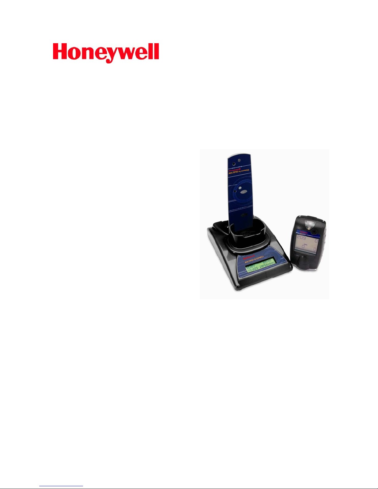
Reference
Manual
IQ Express
Docking Station
for
MultiPro
Honeywell Analytics, Inc.
405 Barclay Boulevard
Lincolnshire, IL 60069
(800) 711-6776
(847) 955-8200
Fax (800) 995-4992
Part number 13-287
Version 4
27 August 2012
Page 2

THE MULTIPRO IQ EXPRESS IS DESIGNED TO INTERFACE WITH
HONEYWELL ANALYTICS GAS DETECTORS.
HONEYWELL ANALYTICS GAS DETECTORS HAVE BEEN DESIGNED FOR
THE DETECTION OF DEFICIENCIES OF OXYGEN, ACCUMULATIONS OF
FLAMMABLE GASES AND VAPORS AND ACCUMULATIONS OF TOXIC
VAPORS.
IN ORDER TO ENSURE THAT THE USER IS PROPERLY WARNED OF
POTENTIALLY DANGEROUS ATMOSPHERIC CONDITIONS, IT IS ESSENTIAL
THAT THE INSTRUCTIONS IN THIS MANUAL AND THE OPERATIONS
AND/OR REFERENCE MANUAL(S) FOR THE GAS DETECTOR(S) BE READ,
FULLY UNDERSTOOD, AND FOLLOWED.
THIS MANUAL IS NOT INTENDED TO REPLACE THE OPERATIONS AND/OR
REFERENCE MANUALS FOR THE GAS DETECTOR. THIS MANUAL IS ONLY
DESIGNED TO AID IN THE INSTALLATION AND OPERATION OF THE IQ
EXPRESS SYSTEM AND SHOULD BE USED IN CONJUNCTION WITH THE
INSTRUMENT REFERENCE OR OPERATIONS MANUAL AT ALL TIMES.
MultiPro IQ Express
Reference Manual
Honeywell Analytics Part Number 13-287
Version 4
Copyright 2012
by
Honeywell Analytics, Inc.
Lincolnshire, IL 60069
All rights reserved.
No page or part of this operation manual may be reproduced in
any form without written permission of the copyright owner
shown above.
Honeywell Analytics reserves the right to correct typographical
errors.
1
Page 3

Table of Contents
Warnings and Cautions 3
A. Signal Words 3
1.Overview 4
1.1 Tests and record keeping 4
1.2 PC Connection 4
1.2.1 USB Connection 4
1.2.2 Ethernet Connection and E-mail 4
1.3 PC Requirements 5
1.4 Instrument Firmware Requirements 5
1.5 Power Requirements 5
1.5.1 Dock with direct USB Connection to PC 5
1.5.2 Multi-Dock Setup with USB Connection 5
1.6 Sensor compatibility 5
1.7 Default Calibration Gas Settings 5
1.8 Calibration Gas Cylinder Regulator Requirements 5
1.9 Dock Location 5
1.10 Delivery 5
2.Installation 5
2.1 Installation Overview 6
2.2 IQ Administrator Pro and PostgreSQL Database Server Installation 6
2.3 IQ Database Manager Software Installation 6
2.4 MultiPro IQ Express PC Software Installation 6
2.5 Install IQ Administrator Pro and PostgreSQL database 8
2.6 Power and Connectivity 8
2.6.1 PC – Single Dock via USB 8
2.6.2 PC – Multi Dock via USB 8
2.7 Connecting the Calibration Gas Cylinder to the Dock(s) 9
2.7.1 Single Cylinder to Single Dock 9
2.7.2 Single Cylinder to Multiple Docks 9
2.7.3 Fresh Air Port Instructions 10
Fresh Air Filter 10
Providing Fresh Air in a Contaminated Environment 11
Option 1: Using a Gas Cylinder to Provide Fresh Air to the Dock 11
Option 2: Using a Sealed Conduit to Provide Fresh Air to the Dock 11
Multi-Dock Setups with Fresh Air Manifold 11
2.8 Initial PC- Dock Connection 12
2.8.1 PC screens 12
2.8.2 Dock screens 13
3.Software 13
3.1 Dock Status (USB Connection) 14
3.2 Dock Controls and Instrument Status 14
3.2.1 Dock Configuration 14
Hardware Configuration 15
Connection Speed 15
Audible Alarm Sensitivity Controls 15
AC Power 15
Pump Diagnostics 15
2
Page 4

LCD Contrast Control 15
Status After Test 16
Battery 16
Calibration Interval 16
Gas Configuration 16
Saving new settings 16
Dock LCD Display 17
Ethernet Controls 17
3.2.2 Instrument Tab 17
3.3 Advanced Settings / Passcode 18
4.Dock Use 19
4.1 Test Sequence 20
4.2 IrDA Connection Issues 21
4.2.1 Connection Lost 21
4.2.2 Outright Failure to Connect 21
4.3 Test Failures 21
4.3.1 No gas detected 21
4.3.2 Span calibration failure 21
4.3.3 Alarm test failure 21
4.3.4 PC Aborted Test 21
5.Menu Items 21
5.1 File Menu 21
5.2 Tools Menu 22
5.2.1 Dock 22
5.2.2 MultiPro 22
5.2.3 Certificates 23
5.2.4 Session Downloading 23
5.3 Help Menu 23
5.3.1 Check for Update 23
5.3.2 About IQ Express 23
6.Software Upgrades 24
Appendix A: USB Architecture with Network Access 25
Appendix B: Calibration Frequency 26
Honeywell Analytics Warranty Gas Detection Products 27
Warnings and Cautions
A. Signal Words
The following signal words, as defined by ANSI Z535.4-1998, are used in the MultiPro IQ
Express Reference Manual.
indicates an imminently hazardous situation which, if not
avoided, will result in death or serious injury.
indicates a potentially hazardous situation which, if not
avoided, could result in death or serious injury.
indicates a potentially hazardous situation, which if not
avoided, may result in moderate or minor injury.
CAUTION used without the safety alert symbol indicates a potentially
hazardous situation which, if not avoided, may result in property damage.
3
Page 5

1. Overview
The MultiPro IQ Express Docking Station
is an automatic calibration station for use
with MultiPro Gas Detectors. The
MultiPro IQ Express Docking Station
automatically performs up to eight critical
tests including sensor identification,
instrument performance, bump and alarm
tests and record-keeping procedures in 1
minute. The station also retains a
historical record of testing and instrument
maintenance in the system's onboard
memory.
The MultiPro IQ Express Docking Station
may be operated as a stand-alone
calibration station, or may be connected to
a PC via USB cable for increased control
over system operations.
When the Dock is operated without a PC
interface, it will operate with the last set of
calibration gas settings that were
uploaded into the instrument.
Unless otherwise specified at the time of
purchase, all MultiPro IQ Express Docks
shipped from Honeywell Analytics are
configured for instruments containing LEL,
O
, CO and H2S sensors with the
2
standard calibration gas settings. In the
event that the dock is to be used as a
stand-alone calibration station with nonstandard alarm settings, the dock must be
reprogrammed with the MultiPro IQ
Express Software.
The IQ Express Configuration Software
must be loaded onto the PC prior to
completing the USB connection.
Note: Do not connect the MultiPro IQ
Express Dock to the PC until the
software has been installed.
1.1 Tests and record keeping
The MultiPro IQ Express Docking Station
automatically performs the following
procedures whenever an instrument is
placed in the dock.
Instrument identification
Battery test
Audible alarm test
Visual alarm test
Vibrating alarm test (if applicable)
Fresh air calibration
Bump test
Record-keeping
Datalogger and Eventlogger download
(Dock must be connected to PC)
In the event that an instrument fails the
bump test, or if the instrument’s calibration
due date has passed, the MultiPro IQ
Express Docking Station will automatically
proceed to a full calibration without further
intervention from the user.
Note: The MultiPro IQ Express Dock
only tests the sensors that are
currently detected by the MultiPro. The
MultiPro only displays readings for
sensors that are actively detected by
the instrument. If the MultiPro does
not show gas readings for a specific
sensor on the instrument display, then
it is not detecting that sensor.
If the instrument fails any of the tests
listed above, the MultiPro IQ Express
Dock will notify the user through the
display on the dock, and through the PC if
the dock is connected to a computer and
the software is running.
Results of tests and calibration attempts
are stored in the dock and uploaded to the
PC if the software has been loaded and
the USB connection is active.
1.2 PC Connection
PC Software must be installed prior to
connecting the MultiPro IQ Express Dock
to the PC. An overview of the installation
procedure is given below in section 2.1.
1.2.1 USB Connection
Every MultiPro IQ Express Dock can be
connected to the PC via the PC’s USB
port.
Note: USB cable length from PC to
dock may not exceed 10 feet.
1.2.2 Ethernet Connection and E-mail
MultiPro IQ Express Docks with the
Ethernet upgrade may be connected to
the PC via USB or via a network. For
Ethernet Connection instructions, follow
the directions given in the IQ Express
Ethernet Instructions booklet.
Docks that are connected by Ethernet
have additional controls at the PC to ping
the dock, to view the Ethernet settings
and to view and test the e-mail system.
In the MultiPro IQ Express, e-mail may be
sent by the dock to a single e-mail
address when a fault is detected at the
dock, but for no other reason. The dock
must be connected to a network via
4
Page 6

Ethernet for the e-mail function to work.
E-mail capability is controlled entirely
through the IQ Database Manager Pro
program. For more information on the email function see Ethernet Controls in
section 3.2.1 below or the IQ Database
Manager Pro manual.
1.3 PC Requirements
Pentium II Processor 400MHz or
better or equivalent.
128MB RAM.
Windows 98*/2000**/XP.
30MB hard drive disk space.
USB Port.
*Honeywell Analytics discourages
multiple IQ Express Dock setups with
PC’s running Windows 98.
**Service Pack 3 for Windows 2000 is
highly recommended.
1.4 Instrument Firmware
Requirements
Instrument firmware version 1.32 or higher
is required in the MultiPro. Firmware
upgrades to the MultiPro may be made
with a PC through the IrDA port.
1.5 Power Requirements
The MultiPro IQ Express Dock is delivered
with an appropriate power supply and a
variety of adapters.
The dock must be plugged into an
appropriate electrical outlet using the
power supply / wall cube that was
included with the dock at the time of
purchase.
1.5.1 Dock with direct USB Connection
to PC
The MultiPro IQ Express must be plugged
into an appropriate electrical outlet using
the power supply / wall cube that was
included with the dock at the time of
purchase. A USB cable is included to
connect the dock to the PC with the USB
cable.
1.5.2 Multi-Dock Setup with USB
Connection
For multi-dock configurations each dock
must be powered using the power supply
that was included with the dock. An
alternate option is to purchase the
optional power supply that is capable of
running up to 4 MultiPro IQ Express
docks. Under no circumstances can
multiple docks be run from a single USB
port or from a USB hub regardless of
whether it is a powered or non-powered
hub.
Power and Connectivity are discussed
in greater detail in section 2.6.
1.6 Sensor compatibility
The MultiPro IQ Express Dock is capable
of processing instruments containing any
combination of O
sensors.
, LEL, CO and H2S
2
1.7 Default Calibration Gas
Settings
Dock
Setting
O2 18% vol.
LEL 50% LEL
CO 50 PPM
H2S 25 PPM
Default Calibration Gas Settings and
Dock Requirements
Default Cal Gas
Setting
1.8 Calibration Gas Cylinder
Regulator Requirements
A demand-flow regulator must be used
with the IQ Express.
1.9 Dock Location
The MultiPro IQ Express Dock should be
located in an area that is not exposed to
direct sunlight.
1.10 Delivery
Each MultiPro IQ Express Calibration
Station is delivered with the following
items:
MultiPro IQ Express Docking Station.
MultiPro IQ Express Configuration
Disc with MultiPro IQ Express Pro
Software, IQ Database Manager Pro
Software and PostgreSQL Database
Server Software.
USB Cable.
Power Supply.
2’ piece of calibration gas tubing with
pre-installed white quick disconnect
fitting.
2. Installation
The MultiPro IQ Express Docking Station
must be configured with a PC prior to use.
Once it has been configured, it may be
used as a stand-alone calibration station
without a PC connection, or connected to
5
Page 7
a PC for increased control over system
operations.
Unless otherwise specified at the time of
purchase, all MultiPro IQ Express Docks
are shipped from Honeywell Analytics
configured with the standard calibration
gas settings, which are shown in section
1.7.
Whenever the user chooses to activate
the MultiPro IQ Express without an active
PC connection, the dock will operate with
the last set of calibration gas settings that
were uploaded into the instrument.
Note: Do not connect the MultiPro IQ
Express to the PC until all three items
on the MultiPro IQ Express Installation
disc have been installed.
2.1 Installation Overview
A number of software programs and a
PostgreSQL Database Server must be
installed to control the MultiPro IQ
Express.
1. Install the PostGreSQL Database
Server and the IQ Administrator Pro
Program as described in the IQ
Administrator Pro Reference Manual.
2. Install the IQ Database Manager Pro
program as described in the IQ
Database Manager Pro Reference
Manual.
3. Install the MultiPro IQ Express PC
Software as described below in
section 2.4.
4. Create a default PostgreSQL
database as described in section 6 of
the IQ Administrator Pro Reference
Manual.
5. If connecting the dock to the PC via
USB, follow the instructions in section
2.6. If connecting the dock via
Ethernet, follow the Ethernet
Instructions booklet.
6. Follow the instructions in section 2.7
for providing calibration gas and fresh
air to the dock(s).
7. For docks that will be connected
permanently by USB port, configure
the docks by connecting them to the
PC’s USB port. If the instrument is to
be connected via Ethernet, follow the
Ethernet Instructions that came with
the dock.
2.2 IQ Administrator Pro and
PostgreSQL Database Server
Installation
The IQ Administrator Pro Program is
contained on the IQ Express Installation
Disk. Place the disk in your PC’s CD tray
and follow the installation instructions
given in the IQ Administrator Pro
Reference Manual that is included with
the IQ Express.
2.3 IQ Database Manager Software
Installation
The Database Manager Pro Program is
contained on the IQ Express Installation
Disk. Place the disk in your PC’s CD tray
and follow the installation instructions
given in the IQ Database Manager
Software manual that is included with the
IQ Express.
2.4 MultiPro IQ Express PC
Software Installation
The PostgreSQL Database Server and IQ
Database Manager Pro Programs should
be installed before proceeding to step 1.
Note: Screens shown below may be
slightly different depending on your
PC’s operating system.
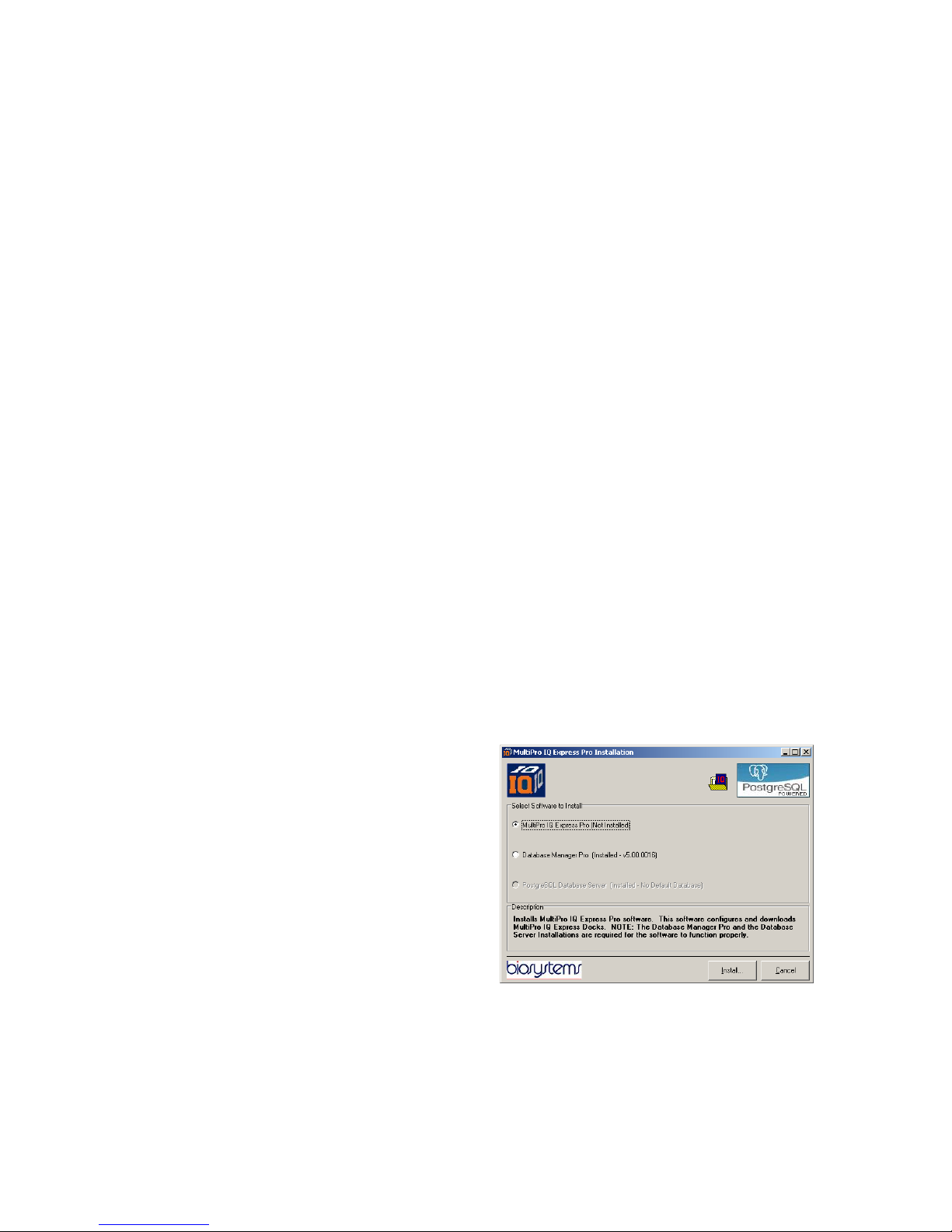
1. The Software Installation screen
should come up automatically once
the installation of Database Manager
is complete. If this screen does not
come up, access the CD drive using
Windows Explorer.
2. Select “MultiPro IQ Express Pro” and
click “Install”. The InstallShield Wizard
will begin the installation.
6
Page 8
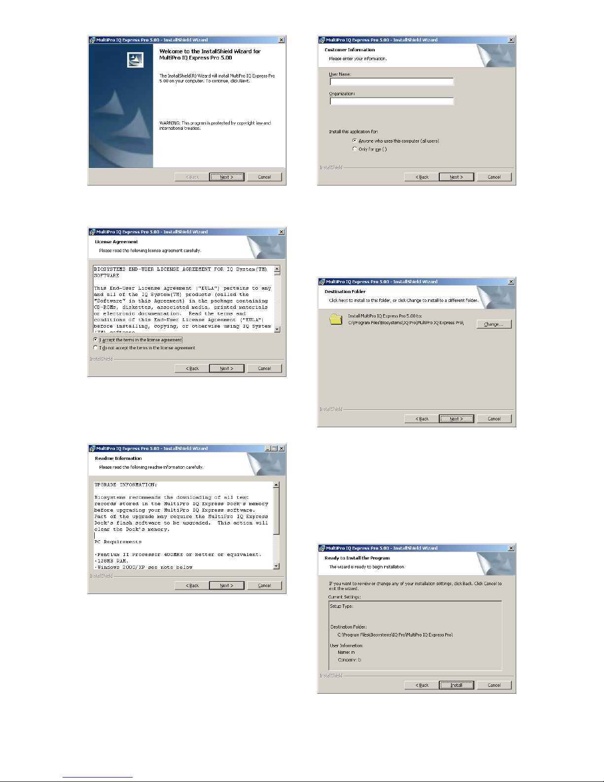
3. Click “Next” to continue with the
installation. The Licensing Agreement
screen will be shown.
4. If you accept the terms of the License
Agreement, click “I accept.....” and
then click “Next” to continue. The
upgrade information and PC
requirements will be shown.
6. Enter the name of the user and the
name of the organization. Then select
whether this application may be used
by “Anyone who uses this computer”
or “Only for me”. Then click “Next.
The destination folder screen will be
shown.
7. To install IQ Express in the default
directory at “C:\Program Files \
Biosystems \ IQ Pro \ MultiPro IQ
Express Pro \” click “Next”. To install
the files to another directory, click
“Browse” and use Windows Explorer
to specify the new location. Click
“Next” once this is accomplished. The
following screen will then be shown.
5. Click “Next” to continue. The
Customer Information screen will be
shown.
7
8. Click “Next” to continue. The status of
the file decompression will be shown.
Page 9
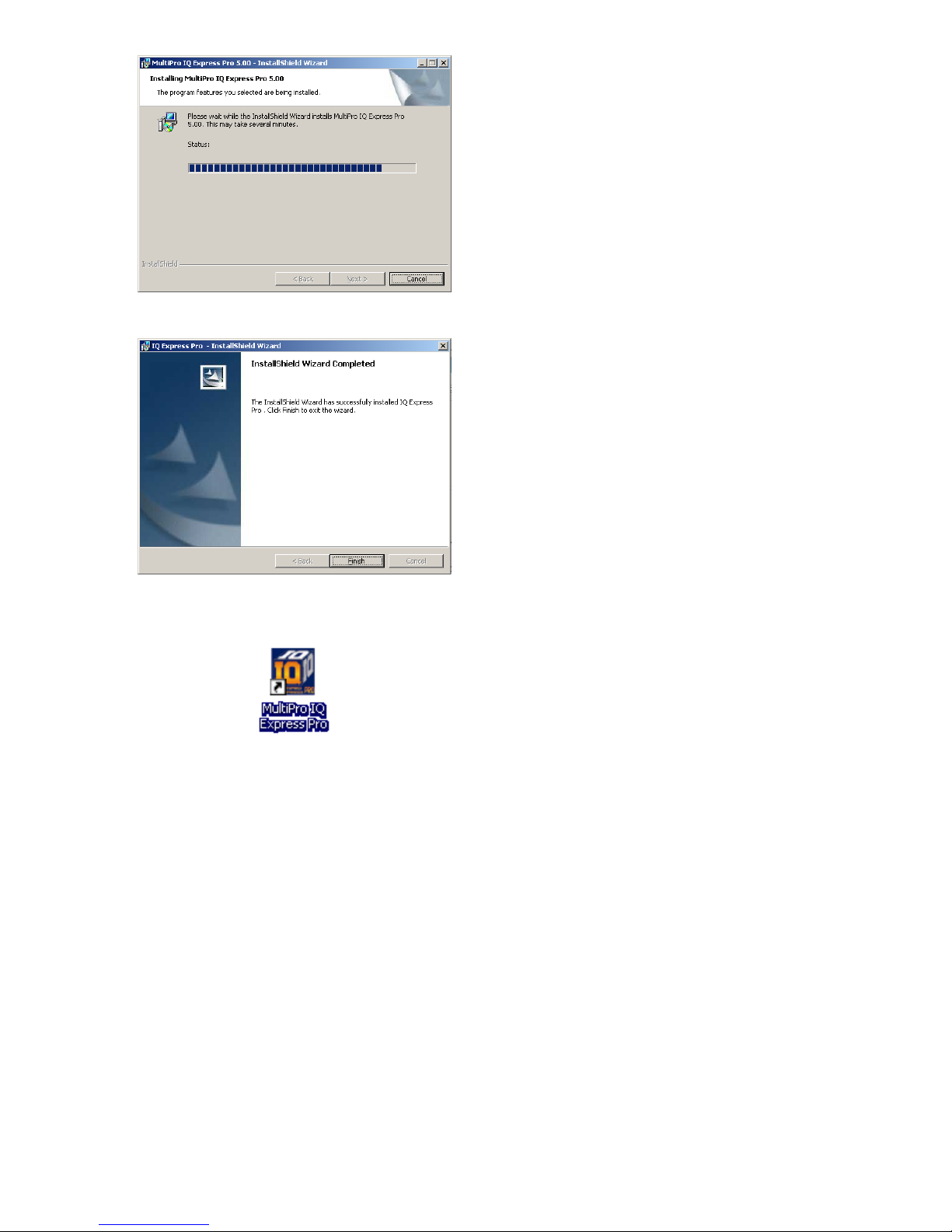
Once the installation is complete, the
following screen will be shown:
9. Click Finish to conclude the
installation. The IQ Express logo will
appear on your desktop.
Note: Do not launch the MultiPro IQ
Express Software again until the
instructions in sections 2.5 – 2.8 below
have been completed.
2.5 Install IQ Administrator Pro
and PostgreSQL database
Proceed to the IQ Administrator Pro
Reference Manual section 6 and follow
the instructions to create and specify the
PostgreSQL database.
2.6 Power and Connectivity
Honeywell Analytics recommends that an
appropriate surge suppressor be used to
protect this equipment against destructive
surge currents and transient voltages.
This section covers providing power to the
IQ Express Docks and connecting them to
your PC. The instructions given below
pertain to standard connections via the
PC’s USB port.
Note: Disregard this section if you are
planning to connect the docks via
Ethernet or if you have purchased the
IQ Express Mounting Bracket.
IQ Express Docks that are Ethernet-ready
are shipped with an Ethernet Instructions
booklet. Proceed to the Ethernet
Instructions booklet if you are planning to
connect the dock to the PC via Ethernet.
Once the instructions in the booklet have
been followed and the IQ Express Dock is
connected, return to section 2.7 for
calibration gas cylinder connection
instructions.
If you have purchased the IQ Express
Mounting Bracket, proceed to the
Assembly Instructions for IQ Express
Mounting Bracket. Once the docks are
correctly installed on the mounting
bracket, proceed to section 2.7.3 for
instructions concerning the Fresh Air
Port(s).
2.6.1 PC – Single Dock via USB
The MultiPro IQ Express must be plugged
into an appropriate electrical outlet using
the power supply / wall cube that was
included with the dock at the time of
purchase. After connecting the dock to
the PC with the USB cable that was
included with the dock proceed to section
2.7 for instructions concerning calibration
gas.
Note: USB cable length from PC to
dock may not exceed 10 feet.
2.6.2 PC – Multi Dock via USB
For multi-dock configurations each dock
must be powered using the power supply
that was included with the dock. An
alternative option is to purchase the
optional power supply that is capable of
running up to 4 MultiPro IQ Express
docks. Under no circumstances can
multiple docks be run from a single USB
port or from a USB hub regardless of
whether it is a powered or non-powered
hub. Once the power requirement for each
dock is satisfied the USB connection to
the PC can be made by using a USB hub
or by connecting the USB cable directly to
the PC.
Note: With a USB hub, USB cable
length from hub to dock may not
exceed 10 feet.
8
Page 10
2.7 Connecting the Calibration Gas
Cylinder to the Dock(s)
Connection requirements for calibration
gas cylinders vary with how many docks
will be connected to the cylinder.
For instructions on connecting the gas
cylinder to a single dock proceed to
section 2.7.1.
For instructions on connecting the gas
cylinder to multiple docks proceed to
section 2.7.2.
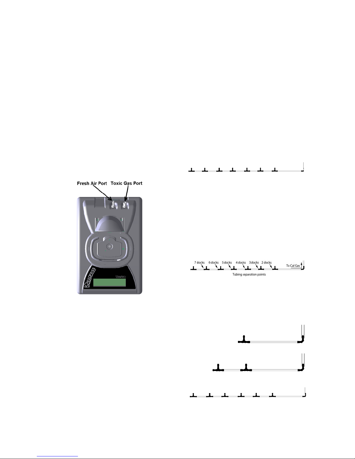
2.7.1 Single Cylinder to Single Dock
1. Insert the demand flow regulator into
the calibration gas cylinder.
2. Slide the open end of the tubing
assembly over the regulator.
3. Connect the end of the tubing with the
white quick disconnect fitting to the
toxic GAS port on the dock (see figure
2.7.1).
regulator. Each IQ Express dock is
able to draw calibration gas at a
maximum rate of 0.75 liters/minute.
The demand flow regulator supplied by
Honeywell Analytics (part number 12-
061) has a maximum output capacity of
3 liters per minute, so it can be used to
calibrate up to 8 docks simultaneously.
Do not connect more than 4 docks to a
single cylinder of calibration gas while
using the 12-061 demand flow
regulator.
The 54-46-115 manifold is comprised of:
(1) small black elbow fitting
(7) small black T-fittings
(6) pieces of gas tubing 5” long
(1) piece of gas tubing 10” long
(1) piece of gas tubing 1” long
54-46-115 Manifold
1. Insert the Demand Flow Regulator into
the calibration gas cylinder.
2. Modify the tubing assembly as follows
depending on how many docks will be
connected. If 8 docks will be used, no
modifications are necessary. For 2 to
7 docks, begin by separating the
tubing at the location described below.
Figure 2.7.1 Gas Ports
4. Proceed to section 2.7.3 for further
instructions concerning the fresh AIR
port.
Once this is accomplished, set the
separated parts aside. The section
that will be used is shown in the
following images (depending on the
number of docks).
2.7.2 Single Cylinder to Multiple Docks
When multiple IQ docks are connected to
a single cylinder of calibration gas, a
Manifold for two docks
manifold is used to disperse the
calibration gas from the cylinder to the
docks.
The manifold is Honeywell Analytics part
number 54-46-115 and includes a detailed
instruction sheet for its use. The manifold
comes with tubing and fittings necessary
for connecting up to 8 docks to a single
cylinder of calibration gas.
Note: Do not exceed the output
capacity of your demand flow
3. Each dock is delivered with a 24”
Manifold for three docks
Manifold for seven docks
piece of tubing with a white quick
disconnect fitting, which is normally
9
Page 11
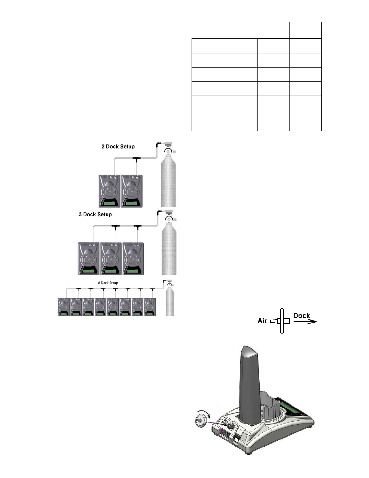
used to connect a single gas cylinder
directly to a single dock. Connect the
white quick disconnect fittings to the
GAS ports on the docks and connect
the open ends to the manifold’s open
t-fittings.
At this point, tubing should run from each
dock’s GAS port to the t-fittings. There
should be no open T-fittings in the
procedure, but there should be one piece
of open tubing on the elbow fitting.
4. Connect the open piece of tubing on
the elbow fitting to the Demand Flow
Regulator.
Final Appearance
Note: Tubing lengths in these images
are not to scale.
2.7.3 Fresh Air Port Instructions
The Fresh Air Port is used to draw the
fresh air sample into the dock for
instrument processing. Check valves
and/or fresh air filters are required
depending on how fresh air is delivered to
the dock. See the chart below for specific
requirements for your setup.
Single Dock in Fresh
Air
Multiple Docks in
Fresh Air
Single Dock w/Zero
Air Cylinder
Multiple Docks
w/Zero Air Cylinder
Single Dock w/Sealed
Fresh Air Conduit
Multiple Docks w/
Sealed Fresh Air
Conduit
Air Filter
at Dock
Yes N/A
Yes N/A
No No
No Yes
Yes No
Yes Yes
Air Filter / Check Valve
Requirements Chart
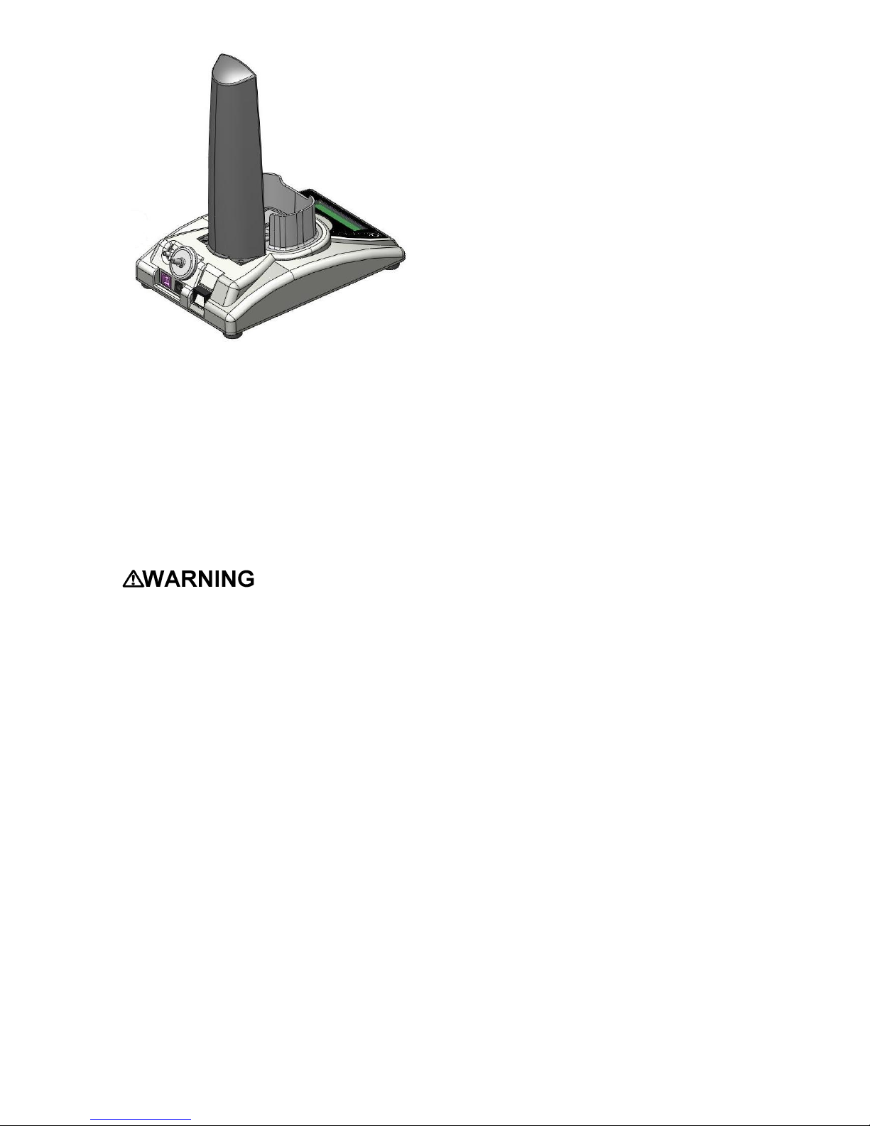
The fresh air filter is placed on the Air Port
at the dock to protect the dock from
contaminants. Check valves are used to
ensure the purity of external fresh air
sources when more than one dock is
used.
Fresh Air Filter
Under normal circumstances, the IQ
Express Dock is located in a fresh air
environment and fresh air is drawn in from
the local environment. A filter is included
with the dock that is used to protect the
dock from contaminants that may
inadvertently enter the dock. The air filter
should be installed if the dock is drawing
fresh air from the immediate surroundings
or if it is drawing fresh air from an external
source via a sealed conduit. The fresh air
filter can be left off if the fresh air source is
a calibration cylinder.
Only one side of the
filter will screw into
the Air Port on the
dock.
Check
Valve(s)
10
Page 12
Providing Fresh Air in a Contaminated
Environment
If the IQ Express is to be located in a
potentially contaminated environment,
fresh air must be delivered to the Air Port
on the dock for use during instrument
processing. This can be accomplished
either by using a cylinder of “zero air” with
a demand flow regulator (option 1 below)
or by plumbing fresh air into the dock in a
sealed conduit from an outside location
that has known fresh air (option 2 below).
Performing the
fresh air calibration in a contaminated
atmosphere will lead to inaccurate and
potentially dangerous readings. Fresh
air containing 20.9% oxygen and no
contaminants must be provided to the
IQ Express Dock for instrument
processing. If fresh air is unavailable
in the immediate area, steps must be
taken to provide fresh air to the dock.
When a secondary fresh air source (either
gas cylinder or sealed conduit) is used
with two or more IQ Express Docks, a
one-way check valve must be placed in
line between the common section of the
fresh air manifold and each of the docks
to ensure the purity of the fresh air source.
See the section below titled “Fresh Air
Manifold” for further instructions.
Option 1: Using a Gas Cylinder to
Provide Fresh Air to the Dock
A calibration cylinder containing “zero air”,
which contains 20.9% oxygen and no
contaminants may be connected to the
gas port labeled “AIR” to provide fresh air
to the dock for calibration. The cylinder
must be equipped with a demand flow
11
regulator. The connection from the
cylinder and regulator to the dock may be
made with standard gas tubing.
For single docks, simply connect the “zero
air” cylinder and demand flow regulator to
the dock’s AIR port using standard gas
tubing. A check valve is not necessary
when a cylinder is used to provide fresh
air to a single dock. The fresh air filter is
also not required in this configuration.
For multiple dock setups (up to 8), a oneway check valve must be placed in the
line between each T-fitting and dock to
ensure the purity of the fresh air source.
See “Multi-Dock Setups with Fresh Air
Manifold” below for further instructions.
The fresh air filter is not necessary when a
gas cylinder is used to provide fresh air to
the dock(s).
Option 2: Using a Sealed Conduit to
Provide Fresh Air to the Dock
Fresh air may also be delivered to the
dock from a known fresh air source via a
sealed conduit that feeds directly from the
source into the AIR port on the dock.
For single docks, install the fresh air filter
as discussed above and simply plumb the
fresh air source directly into the dock’s
AIR port.
For multiple dock setups in which fresh air
is provided to the dock via sealed conduit,
begin by installing the fresh air filter on
each dock. A one-way check valve must
be placed in the line between the t-fitting
in the fresh air manifold and each dock to
ensure the purity of the fresh air source.
See “Multi-Dock Setups with Fresh Air
Manifold” below for further instructions.
Multi-Dock Setups with Fresh Air
Manifold
For more information on this, see
Applications Note # 13-291.
The 54-46-116 manifold is necessary for
use when more than one dock is to be
used with an external fresh air source,
whether it be a cylinder of “zero air” or a
sealed conduit to a fresh air source.
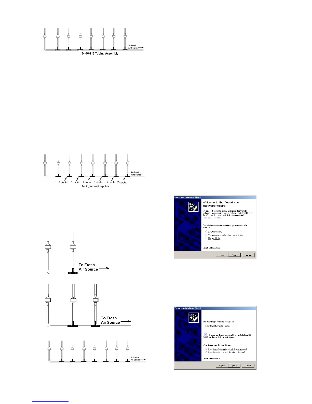
The 54-46-116 manifold is comprised of:
(7) small black T-fittings
(8) clear one-way check valves
(18) pieces of gas tubing 5” long
(1) piece of gas tubing 10” long
Page 13
1a. If calibration gas cylinder and proceed
to step 2.
1b. If the fresh air source is a sealed
conduit from an external fresh air
source, install the fresh filter on each
dock as described above and proceed
to step 2.
2. Modify the tubing assembly as follows
depending on how many docks will be
connected. If 8 docks will be used, no
modifications are necessary. For 2 to
7 docks, begin by separating the
tubing at the location described below.
Once this is accomplished, set the
separated parts aside. The section
that will be used is shown in the
following images (depending on the
number of docks).
3. Connect the pieces of tubing above
the check valves to filter that was
installed on the dock in step 2.
At this point, the tubing assembly should
be connected to each dock’s AIR port.
4. Connect the only open piece of tubing
(below the black t-fittings) to the
demand flow regulator on the gas
cylinder or to the conduit for the
external source of fresh air.
2.8 Initial PC- Dock Connection
Once the software has been installed, and
the USB wire(s) is/are plugged into the
USB port, the Found New Hardware
Wizard screen will be shown on the PC
and a number of messages will be shown
on the MultiPro IQ Express Dock.
2.8.1 PC screens
The Found New Hardware screens will be
shown whenever a dock is plugged into a
new USB port, and also whenever a dock
is plugged into a USB Port that was most
recently used for a different device.
NOTE: These screens will vary
depending on your PC’s operating
system.
Fresh Air Tubing for 2 Docks
Fresh Air Tubing for 3 Docks
Fresh Air Tubing for 8 Docks
12
The software will prompt to ask if it should
connect to Windows Update to search for
software. Make a selection based on how
you would like to use your PC’s operating
system and click Next to continue. The
Wizard will proceed to search for the USB
drivers.
Select “Install the software automatically”
and click “Next”.
Page 14
↓
The IQ Express is ready to go once it
alternates between the following two
screens.
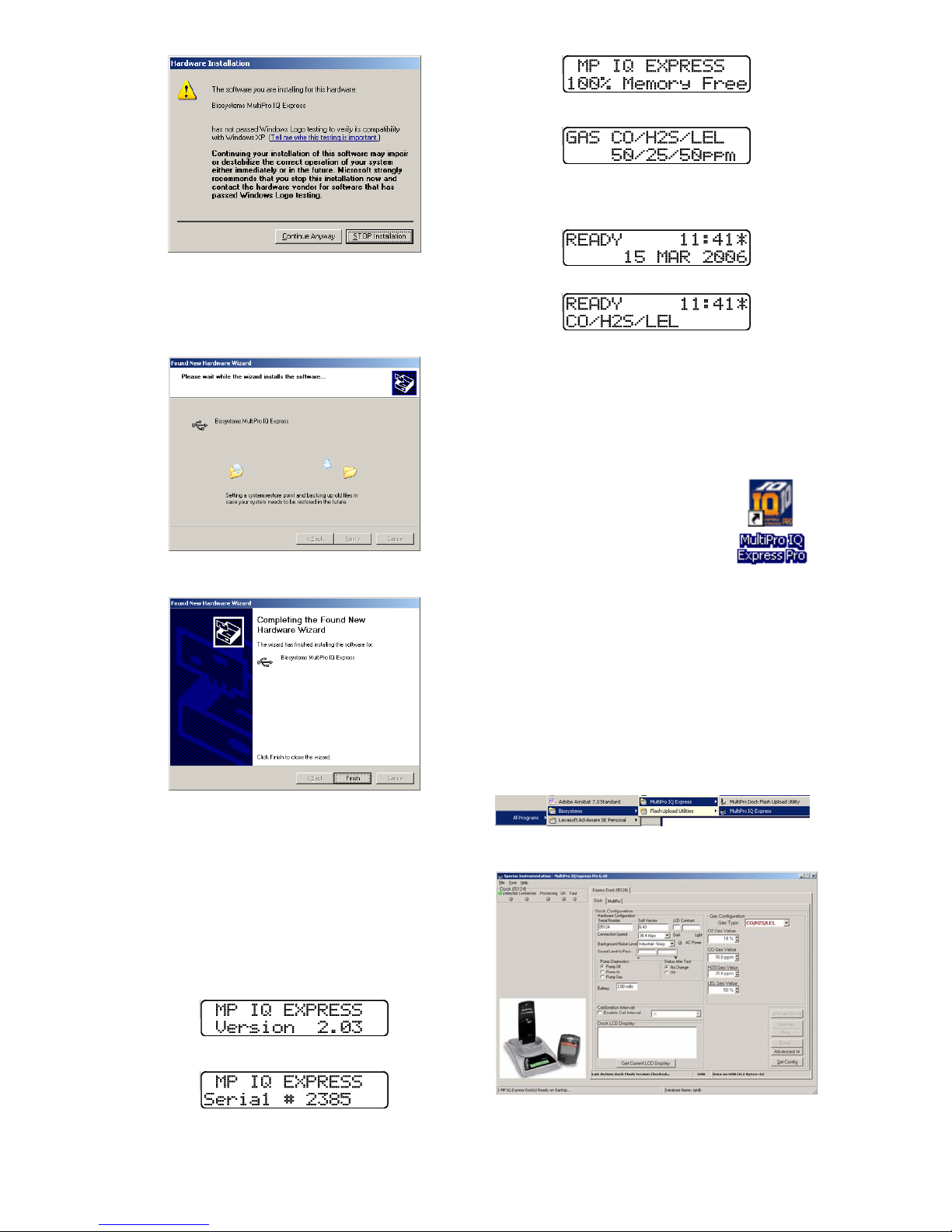
In Windows XP, a warning screen will be
shown stating that MultiPro IQ Express
software has not passed Windows Logo
testing. Click “Continue Anyway” (XP
Only). The installation will then continue.
The software will notify you when the
process is complete.
Click “Finish”.
2.8.2 Dock screens
Once the connection is made, the dock
will display its software version number,
serial number, and the calibration gas
type and expected calibration gas
concentration whenever it is plugged in.
The MultiPro IQ Express Dock is ready to
go once it displays “READY” with the gas
type, time and date.
Note: The asterisk to the right of the
time indicates that the dock is
connected to the PC and that the
MultiPro IQ Express Pro PC software is
running.
3. Software
To launch the IQ Express
Software, click on the IQ
Express icon on your PC’s
desktop.
Note: The Database
Manager must be
launched prior to launching the
MultiPro IQ Express Software to
establish a database.
The software may also be launched by
accessing the program through the start
button and selecting Programs /
Biosystems / MultiPro IQ Express /
MultiPro IQ Express (unless another
location was specified during the
installation).
The following screen will be shown once
the software is launched.
↓
↓
13
The screen is divided into right and left
sides. The left side gives the status of the
docks that are currently installed and
Page 15
recognized. At the top of the right side of
the screen there is a tab for each dock
that is currently installed and recognized.
Within each dock tab are two sub-tabs:
one for dock controls and one that shows
the calibration status and details for the
instrument that is currently in the dock.
3.1 Dock Status (USB Connection)
Note: If the dock is connected to the
PC via Ethernet, see the Status
Indicators section of the IQ Ethernet
Instructions Booklet.
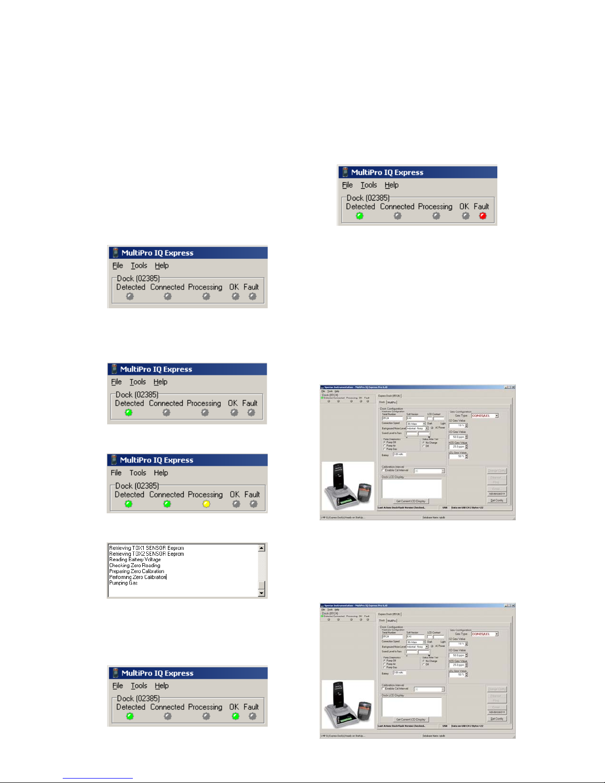
The current status of each dock is shown
in the left column. When there are no
detectors in the dock, each of the status
indicators will be shown in grey.
When a detector is placed in the dock, the
indicator will change to reflect the new
status. Status changes are also be shown
on the dock’s LCD.
For more information regarding
template settings, see the IQ Database
Manager Pro Reference Manual.
If a fault is detected and the dock is
unable to complete the tests, the red fault
light will be shown on the screen. Details
of the fault will be listed in the input box on
the right side of the screen under the
instrument tab. See section 3.2.2 for
details on faults.
3.2 Dock Controls and Instrument
Status
The right side of the screen contains
individual controls for each MultiPro IQ
Express Dock. Each dock has its own
page, which can be accessed by clicking
on the appropriate tab at the top of the
page. Within each dock’s page are two
sub-tabs. One contains specific
information on the dock itself. The other
displays information on the instrument that
is currently recognized in the dock.
During processing, the Processing
Indicator is shown in yellow.
The operations being performed on the
instrument are listed as they occur.
If the dock is able to successfully
complete the processing dictated by the
instrument’s template in the IQ Database
Manager Pro Program, OK will be shown
in green.
Note: If the “Change Config” button is
enabled, press it before making any
changes to the settings.
3.2.1 Dock Configuration
Click on the Dock tab to access the dock
settings.
14
Page 16
To change the configuration of the
MultiPro IQ Express Dock that is
displayed, click on the “Change Config”
button at the lower right of the screen.
Once the dock configuration is uploaded,
the “Set Config” button will be enabled.
Once changes are made, click on the “Set
Config” button to save the new settings.
Calibration values
shown in the Gas Values columns
must match those appearing on the
calibration gas cylinder(s) that will be
used to calibrate the detector. Nonmatching calibration gas and
calibration gas value settings will lead
to inaccurate and potentially
dangerous readings.
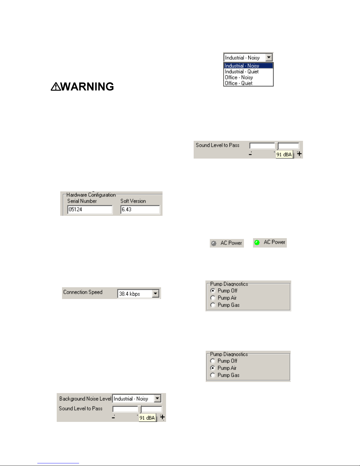
Hardware Configuration
The hardware configuration section
contains the serial number and software
version number of the dock at the upper
left corner.
This information may not be changed with
the software. Software updates will cause
the software version to change.
Connection Speed
The IrDA connection speed is given below
the serial number and software version.
The default connection speed is 38.4
kbps, although settings from 2400 bps to
115.2 kbps are available.
levels. For the best results, select the one
that most closely approximates the
background noise level expected during
testing.
The Minimum Sound Level setting
determines the minimum amount of sound
required to pass the alarm test. The
higher the setting, the louder the alarm will
need to be to pass the test. The sound
level is given in decibels when the cursor
is placed over the slider.
The minimum sound level that will be
accepted by the software is 85 dBA.
AC Power
The AC Power indicator is located directly
beneath the connection speed setting. If
the dock is being powered by the USB
cable, the AC Power will appear grey.
When the dock is being powered by an
AC power source, the AC Power indicator
will appear green.
or
Pump Diagnostics
Pump settings are controlled through the
Pump Control section on the Dock
Settings page.
Honeywell Analytics recommends leaving
the connection speed at the default setting
unless you are experiencing frequent
communication problems in the form of a
loss of connection. If connection is
frequently lost, adjust the connection
speed down gradually until the problem is
resolved.
Audible Alarm Sensitivity Controls
The audible alarm sensitivity controls
allow the user to customize the audible
alarm test criteria.
The Background Noise Level adjustment
offers four levels of background noise
15
Click “Pump Gas” to draw span calibration
gas through the right gas port at the back
of the dock. Click “Pump Air” to draw the
fresh air sample through the left gas input
port.
Either pump will run until “Pump Off” is
selected.
LCD Contrast Control
At the right side of the Dock Configuration
box is the LCD (Liquid Crystal Display)
Contrast Control.
Page 17
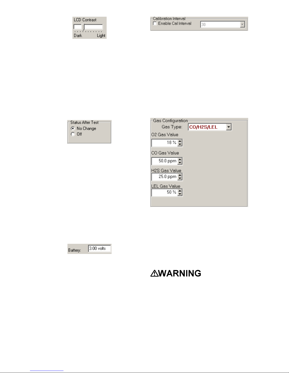
To darken or lighten the display on the
dock, move the slider as appropriate. The
dock will not show the new LCD setting
until the “Set Config” button is pressed.
Status After Test
Once the MultiPro IQ Express Dock
finishes processing an instrument, it can
be programmed to turn the instrument off,
or to leave it in the state that it was in
(either on or off) when it was placed in the
dock. The Status After Test control is
located beneath the LCD Contrast Control
near the center of the screen.
If “Status After Test” is set to Off, the
MultiPro will automatically be turned off by
the dock once the instrument has been
processed.
If “Status After Test” is set to “No
Change”, the instrument will return to the
state it was in when it was placed in the
dock.
Battery
The battery level shown on the dock tab is
for the internal battery in the MultiPro IQ
Express Dock. This battery serves to
keep the real time clock accurate while
the dock is unplugged and should not be a
concern to the user unless the battery
level drops below 2.50 Volts.
Calibration Interval
The Dock’s calibration interval settings are
controlled from the Dock Tab and are
located below the battery level and above
the LCD Display box. The dock’s
calibration interval is the maximum
number of days that the dock will allow to
pass between calibrations for any
instrument that is placed in the dock. If an
instrument is placed in the dock and the
interval has been exceeded, the dock will
automatically initiate a full span calibration
of the instrument regardless of the results
of the bump test or the instrument’s own
calibration status.
To use the setting, click on Enable Cal
Interval and set the interval to the number
of days between calibrations. Note that
this setting may cause the instrument
to undergo a full calibration even when
the instrument itself is not due for
calibration.
Gas Configuration
The calibration gas configuration for the
dock is located on the right side of the
window. If the values are shown in red
text, they can be changed. If the values
are shown in black text and you wish to
change them, press “Change Config”.
Note: The gas values shown in the gas
configuration screen are the values that
will be used in calibrating the MultiPro
instruments that interface with the dock
regardless of the MultiPro’s own built-in
calibration gas settings.
To change the calibration gas value, use
the arrows to the right of the gas value
input box to increase or decrease the
value.
Calibration values
shown in the Gas Value column must
match those appearing on the
calibration gas cylinder(s) that will be
used to calibrate the detector. Nonmatching calibration gas and
calibration gas value settings will lead
to inaccurate and potentially
dangerous readings.
Saving new settings
When all necessary changes have been
made, press the “Set Configuration”
16
Page 18
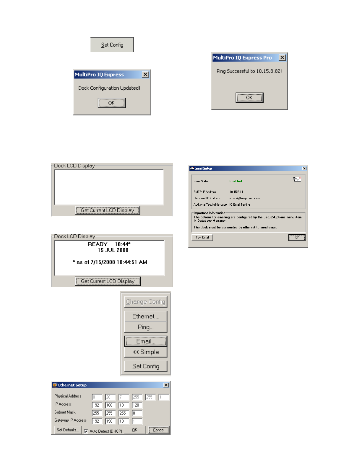
button to upload the new settings to the
dock.
The software will notify you once the dock
configuration has been updated.
To test the dock connection, press the
Ping button. A status window will be
shown to indicate whether the ping was
successful or not.
Dock LCD Display
At the lower left corner of the Dock status
tab is Dock LCD Display window. This is
most often used when a dock is controlled
remotely via Ethernet where the PC user
is unable to physically see the dock.
To view the dock’s Display, click on “Get
Current LCD Display”.
Ethernet Controls
For docks that are
connected by
Ethernet, there are
three additional
controls on the lower
right corner of the
display: Ethernet,
Ping and E-mail.
To view the Ethernet
settings, click on the
Ethernet button
The dock’s e-mail settings are controlled
through the Database Manager Pro
program, but can be viewed by clicking on
the e-mail button. The e-mail status, IP
Address of the dock, recipient e-mail
address and text of the e-mail message
are shown.
To test the e-mail ability of the dock, press
the Test E-mail button at the lower left.
An e-mail will be generated and sent to
the recipient e-mail address that is listed.
Press OK to close the Email Setup
window.
3.2.2 Instrument Tab
The MultiPro tab shows instrument
information for the detector that is
currently in the dock. The right side of the
tab is identical to the Dock Status tab
section discussed above. The blank
space at right is an output box that shows
detailed instrument information as it is
processed.
17
Page 19
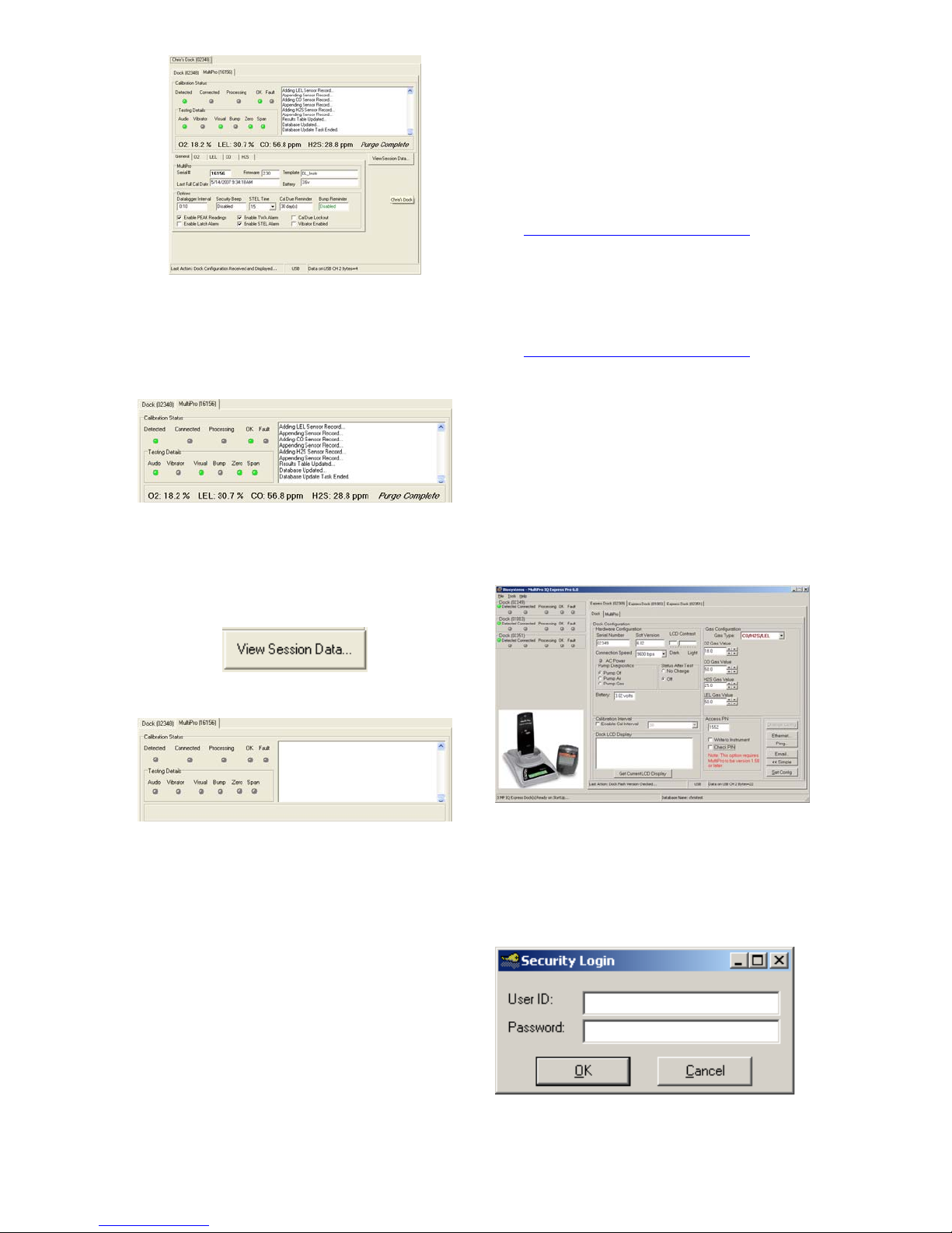
The output box is updated as the
instrument is detected, connected, and
processed. When faults occur, the details
of the fault will be shown and a red fault
light will be shown. Below, a span
calibration failure is the cause of the fault.
If the datalogger has been downloaded,
the “View Session Data” control will
appear on the right. Click on “View
Session Data” to directly access session
information for the instrument using the
BioTrak Program.
1. Verify that the MultiPro instruments
have firmware version 5.0 or higher.
Instrument firmware version is shown
in the start up screens for the
instrument.
If needed, new MultiPro Firmware can
be downloaded at no charge from the
Biodownload’s website at
http://www.biodownloads.com
2. Verify that the MultiPro IQ Express
Dock contains firmware version 5.0 or
higher. New dock firmware can also
be downloaded at no charge from the
Biodownload’s website at
http://www.biodownloads.com
3. Select the dock that will be used to
write the PIN (Personal Identification
Number) to the instrument. Connect
the dock to the PC either by USB port
or by Ethernet port. If using an
Ethernet connection, the Ethernet
setting must be configured to “Live”. If
more than one dock will be used to
update the instruments, perform steps
4-10 for each dock.
4. Open the IQ Express software.
.
.
If the dock is currently empty, none of the
status indicators will be lit.
3.3 Advanced Settings / Passcode
The MultiPro IQ Express Dock may be set
to verify a specific 4-digit passcode (PIN)
in any instrument that interfaces with the
dock. If the dock detects a PIN in the
instrument that matches its own PIN, it will
process the instrument. If the dock fails to
detect a PIN, or recognizes a nonmatching PIN, it will not process the
instrument.
To use the passcode feature a PIN must
be entered into the MultiPro IQ Express
Software and then uploaded to every
instrument that will interface with the dock.
Each dock must then be programmed with
the same PIN and set to check for the
code in the instruments.
5. Click “Advanced” in the row of buttons
on the lower right. The software will
automatically show the Security Login
screen and prompt you for your user
name and password. If the
“Advanced” button is not shown, click
on “Change Config” first to access it.
6. Enter a valid User ID and Password.
The Access PIN settings will be
shown:
18
Page 20
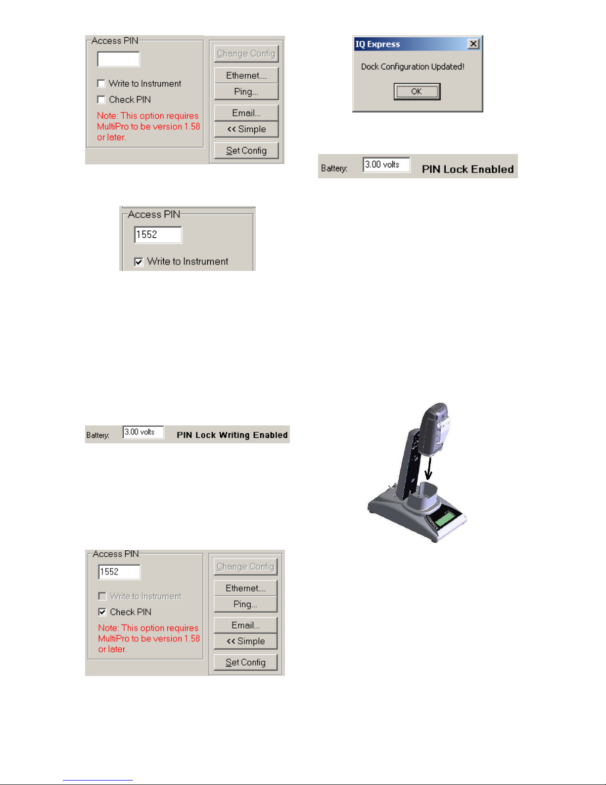
7. Enter a unique 4-digit PIN in the input
box under Access PIN and click on
“Write to Instrument”.
8. Click “Set Config” to tell the dock to
upload the PIN setting to the
instruments. The software will
automatically show the Security Login
screen a second time and prompt you
for your user name and password.
Once a valid User ID and Password
have been entered, “PIN Lock Writing
Enabled” will be shown in the dock
configuration window. The dock is
now ready to upload the PIN to the
instruments.
11. Click OK. “PIN Lock Enabled” will
then be shown in the PC software in
the dock configuration window.
The dock will now verify the PIN in any
instrument that interfaces with it.
12. For every other dock in the system,
access the dock’s advanced settings,
enter the PIN, click on “Check PIN”
and click the “Set Config” button.
With PIN lock enabled, only instruments
with a PIN matching the dock’s PIN will be
processed.
4. Dock Use
Once the MultiPro IQ Express is
connected to the gas cylinder(s) and has
been properly configured, it is ready to
accept the MultiPro gas detector.
The MultiPro must be turned on when it is
placed in the dock.
9. Place the instrument(s) that is/are to
be configured with the PIN in the dock
while PIN Lock Writing is enabled.
10. Once the PIN has been uploaded to all
of the instruments, access the dock’s
advanced settings again and click on
“Check PIN”. Then click the “Set
Config” button.
Enter your User ID and password again
when the Security Login window is shown.
A window will be shown to indicate that
the dock configuration has been updated.
Note: If the MultiPro has just been
turned on, wait at least three minutes
after the conclusion of the startup
sequence to allow the readings to fully
stabilize before placing the instrument
in the dock.
Note: If a sensor has just been
replaced, it must be allowed to stabilize
before placing the instrument in the
dock. See the sensor replacement
section of the MultiPro Reference
Manual for further information on
sensor stabilization.
If you plan to test the instrument with the
pump attached, insert the orange spacer
19
Page 21
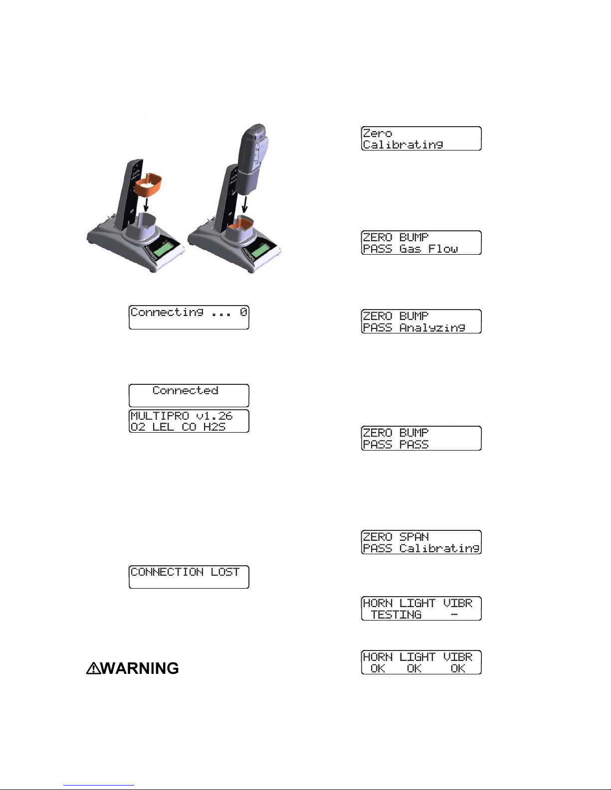
between the pump and the MultiPro IQ
Express Dock as shown below. The nubs
on the spacer should face down and be
flush with the IQ Express Dock housing.
Once the spacer is in, insert the detector
into the dock.
Once the dock recognizes the instrument,
it will show the following screens.
If fresh air is unavailable, a cylinder of
“zero air” containing 20.9% oxygen
and 0 PPM toxic gases must be
connected to the fresh air port with a
demand flow regulator and a piece of
tubing whenever an instrument is in
the MultiPro IQ Express Dock.
Once the zero calibration is complete, the
dock will flow gas to the instrument in
order to perform the “bump” test. If the
instrument is due for calibration, the dock
will bypass the bump test and proceed
directly to the span calibration.
Once the instrument responds to the gas,
the dock will analyze the response to
determine if the instrument passes the
bump test.
Once the connection is made, the IQ
Express will display “Connected”, followed
by the instrument type, software version
and recognized sensors.
Note: MultiPro Instrument firmware
version 1.26 or greater is required for
interface with the MultiPro IQ Express
Dock. Attempts to use the MultiPro IQ
Express Dock with instruments with
earlier firmware versions will result in
errors.
If the dock recognizes the MultiPro but is
unable to maintain the connection, the
following screen will be shown:
See section 4.2 for more information of
connection issues
4.1 Test Sequence
Once the instrument has been
recognized, the zero calibration will begin.
Performing the
fresh air calibration in a contaminated
atmosphere will lead to inaccurate and
potentially dangerous readings. The IQ
Express must be located in a fresh air
environment containing 20.9% oxygen
and no toxic gases during calibration.
20
The gas detector will pass the bump test if
the sensor response to the gas is within
10% if the reading is lower than the
expected sensor output or within 20% if
the reading is higher than the expected
sensor output. If the bump test is passed,
the dock will proceed to the alarm tests.
If the instrument fails the bump test or if
the instrument’s calibration due date has
passed, the dock will automatically bypass
the bump test and proceed to a full
instrument calibration without further input
from the user.
Following successful bump test or
calibration, the dock will test the
instrument’s alarm systems.
If all alarms are operational, the following
screen will be shown.
See section 4.3 for further details on
assessing test failures.
If all tests have been passed, the following
screen will be shown.
Page 22
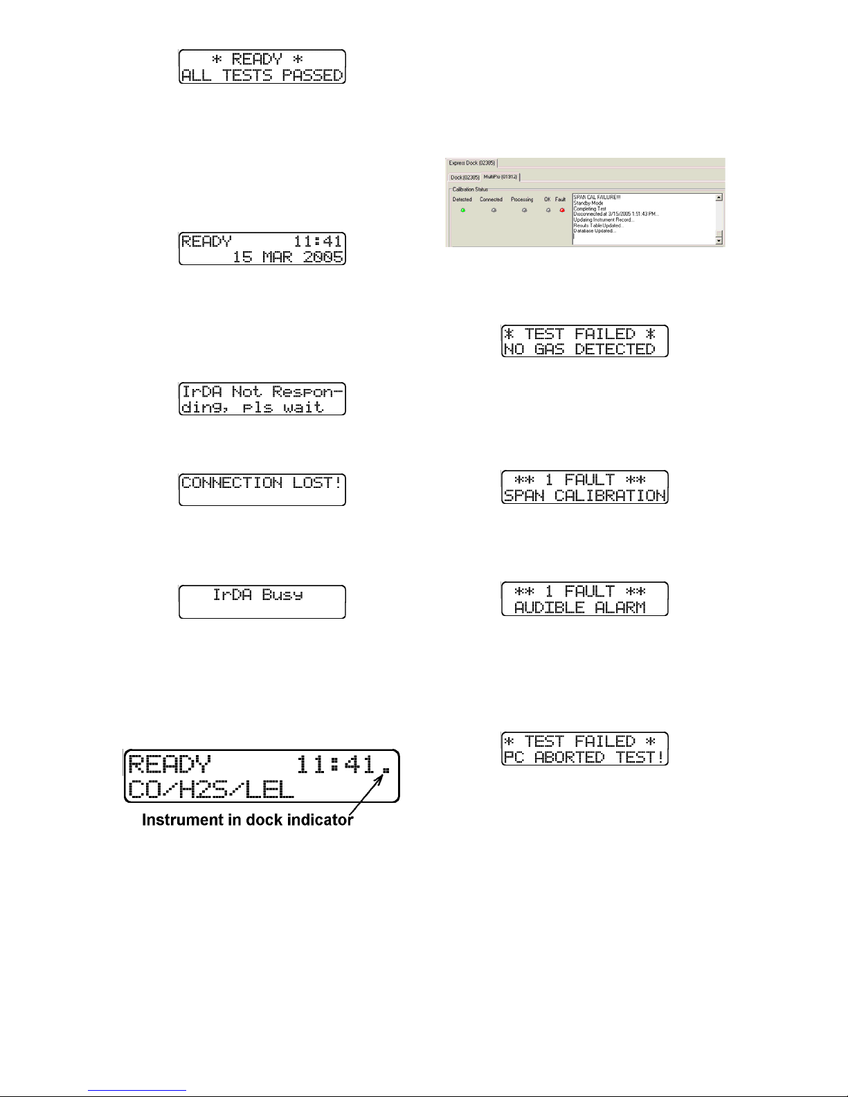
Remove the detector from the dock. The
detector is now fit for use.
Once the detector is removed from the
dock, the dock will reset itself and prepare
itself for the next instrument. In
approximately 10 seconds the display will
show the READY screens. The dock is
then ready for the next detector.
4.2 IrDA Connection Issues
4.2.1 Connection Lost
In the event of a loss of communication
between the dock and the instrument, the
LCD will first indicate that the IrDA is not
responding.
If the dock fails to reestablish the
connection, the LCD will indicate
“Connection Lost”.
for the failure will be shown on the dock’s
LCD. If the Express Software is running
and the dock is properly connected to the
PC, the fault will also be indicated in the
output box on the instrument tab in the IQ
Express software.
4.3.1 No gas detected
If the detector fails to respond to the
calibration gas, the message “NO GAS
DETECTED” will be shown.
4.3.2 Span calibration failure
If the IQ Express is unable to complete
the span calibration, the dock will show
the failure on the LCD. The failure will
also be shown in the output box on the
instrument page in the PC software.
Remove the instrument from the dock.
The dock should reset itself in
approximately 10 seconds.
“IrDA Busy” may also be shown.
4.2.2 Outright Failure to Connect
If the MultiPro is placed in the dock and
connection fails outright, a dot will appear
on the screen to the right of the date. The
dot is an indicator that the instrument IS in
the dock, but the dock is unable to
establish any type of connection to it.
The dot will disappear as soon as the
dock establishes connection with the
dock.
If the dot persists, take the MultiPro out of
the dock and turn it on before returning it
to the dock. If that fails to correct the
problem, call Honeywell Analytics for
more information.
4.3 Test Failures
Failures can occur for a number of
reasons. When a fault occurs, the reason
4.3.3 Alarm test failure
If the dock fails to recognize an alarm that
should be present, it will indicate it on the
display screen following the alarm test.
The failure will also be indicated in the
software in the instrument information.
4.3.4 PC Aborted Test
If the PC is unable to complete the tests
for any reason, the following screen will
be shown:
This message may be shown for a variety
of reasons. See the Calibration Status
output box for further details.
5. Menu Items
5.1 File Menu
The File menu contains the Exit Control
and a control for directly launching the
Database Manager program.
21
Page 23
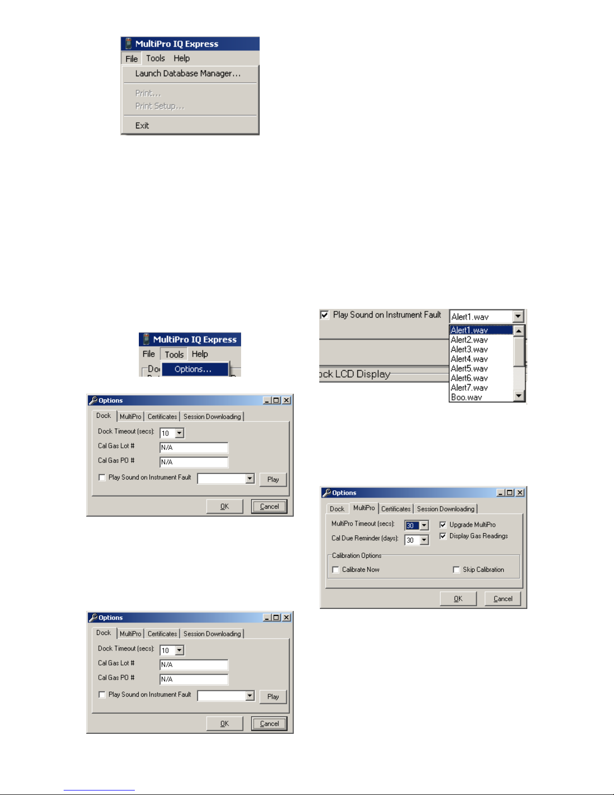
5.2 Tools Menu
The Tools menu contains options for the
MultiPro IQ Express including the
following:
Dock Timeout Setting
Calibration Gas Lot Number Entry (for
tracking purposes)
Instrument Settings for the detector
including the Timeout Setting and the
Calibration Due Reminder Setting
Settings for Printing Calibration and
Bump Test Certificates.
Click on Tools / Options to access the
settings.
The Dock Timeout Setting controls the
amount of time that needs to pass after
connection between the dock and the PC
is lost before the system will notify you
that the connection has been lost.
Options are given in whole numbers
between 1 and 10 seconds. To change
the setting, click on the arrow to the right
of the timeout setting to access the list
and select the new setting.
The Calibration Gas Lot Number is an
input box that allows the user to enter the
lot number into the PC’s records. The lot
number will then be shown on any
calibration certificates that are printed.
To select a specific sound that will be
played when the dock experiences a fault
condition, first click the checkbox next to
“Play Sound on Instrument Fault” and
then select the sound from the list in the
drop down box.
The Options screen will then be shown.
5.2.1 Dock
The Dock Tab under Tools / Options
includes settings for the Dock Timeout,
Calibration Gas Lot Number, Purchase
Order # and the sound setting that the
dock will use to indicate instrument faults.
Each dock has its own unique settings.
5.2.2 MultiPro
The MultiPro tab contains settings for the
MultiPro instrument including the Timeout
setting, the Calibration Due Reminder
setting, the option to automatically update
MultiPro Firmware and calibration options.
The Timeout setting controls the amount
of time that needs to pass after
connection between the dock and the PC
is lost before the instrument will reset
itself. Options are in 5-second increments
from 5 to 30 seconds. To change the
setting, click on the arrow to the right of
the timeout setting to access the list and
select the new setting.
The Calibration Due Reminder setting
controls the amount of time that needs to
22
Page 24
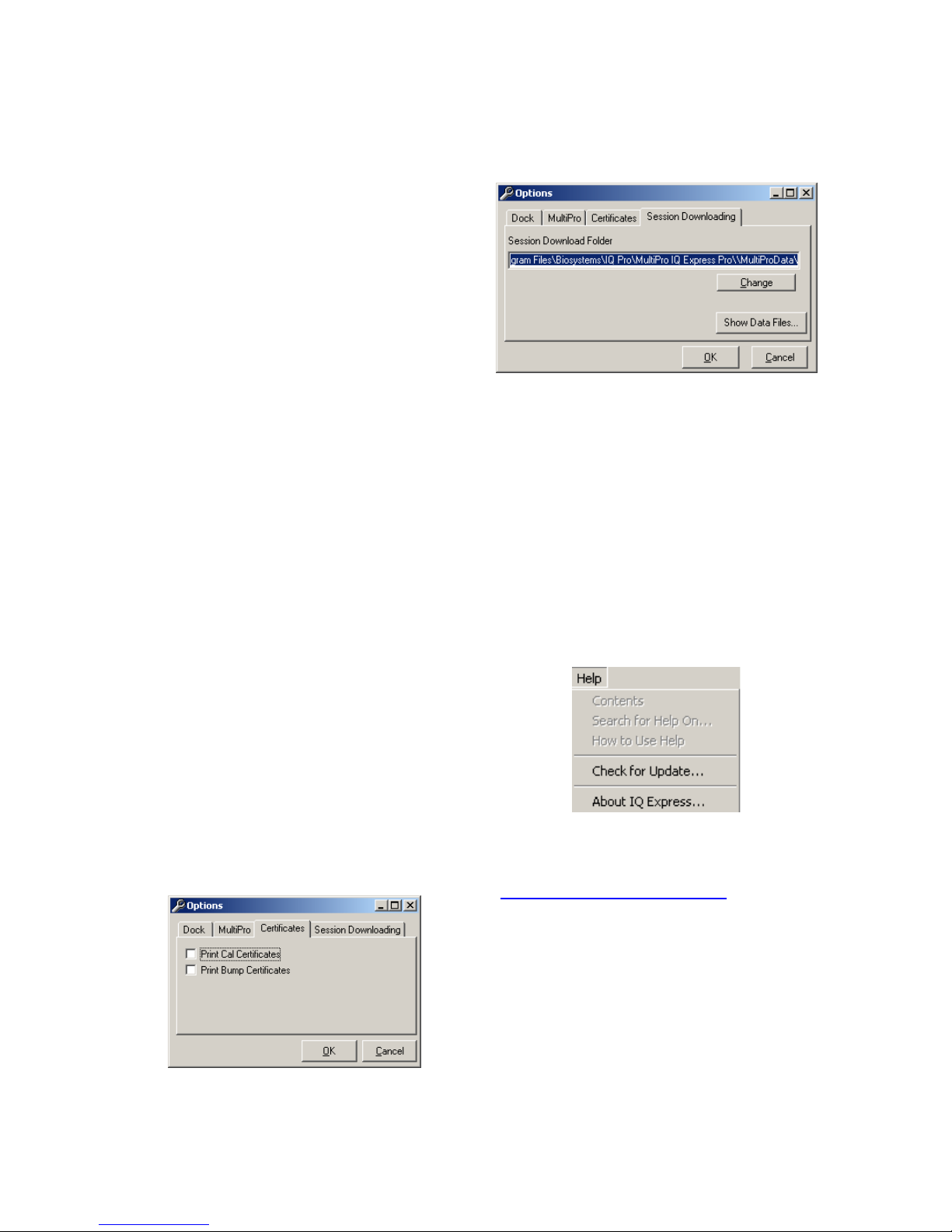
pass without a successful calibration
before the MultiPro will remind you that
calibration is due. The reminder can be
set to any whole number between 1 and
180 days. To disable the calibration due
reminder, change the setting to “0”. To
change the setting, click on the arrow to
the right of the timeout setting to access
the list and select the new setting.
The checkbox to the left of “Upgrade
MultiPro” controls automatic MultiPro
Firmware updates by the IQ Express Dock
whenever a MultiPro is placed in the dock.
Click on the box to enable the automatic
updates.
The checkbox to the left of “Display Gas
Readings” controls whether gas readings
are shown on the IQ Express dock during
instrument processing.
The MultiPro firmware must be
downloaded and stored in the appropriate
folder for the updates to take place. The
folder location is on your local hard drive
under Program Files.
New firmware files for MultiPro
instruments must be stored in the
following folder: C:\ Program Files \
Biosystems \ Flash Upload Utilities \
MultiPro.
Two calibration options are listed near the
bottom of the window.
Select “Calibrate Now” to automatically
perform a full calibration whenever an
instrument is placed in the dock.
Select “Skip Calibration” to automatically
skip the calibration of any instrument that
is placed in the dock.
5.2.3 Certificates
The Certificates tab provides controls for
the automatic printing of Calibration and
Bump Test Certificates.
bump-tested daily though the IQ Express
Dock.
5.2.4 Session Downloading
The session downloading option contains
the control for the file location for session
downloads.
To change the destination directory for the
downloaded files, either type the address
in directly or use the “Browse” button to
locate it.
To view stored data files in the download
folder, press the “Show Data Files” button.
Once the data files are shown, if BioTrak
version 7.40 or later is installed, clicking
on one of the stored files will automatically
launch BioTrak.
5.3 Help Menu
The Help menu contains two options
“Check for Update” and “About IQ
Express”.
5.3.1 Check for Update
The “Check for Update” option links to the
Biodownload’s Software Download site at:
http://www.biodownloads.com
5.3.2 About IQ Express
The About IQ Express contains two tabs
to convey information about the dock and
the PC that is controlling it. The MultiPro
IQ Express Pro tab shows the dock’s
firmware version and basic information
.
Click on the check box next to the option
to select it. Note that a great deal of
paperwork could be generated if “Print
Bump Certificates” is selected and a large
number of instruments are in use that are
23
Page 25
program, which is located in the same
directory.
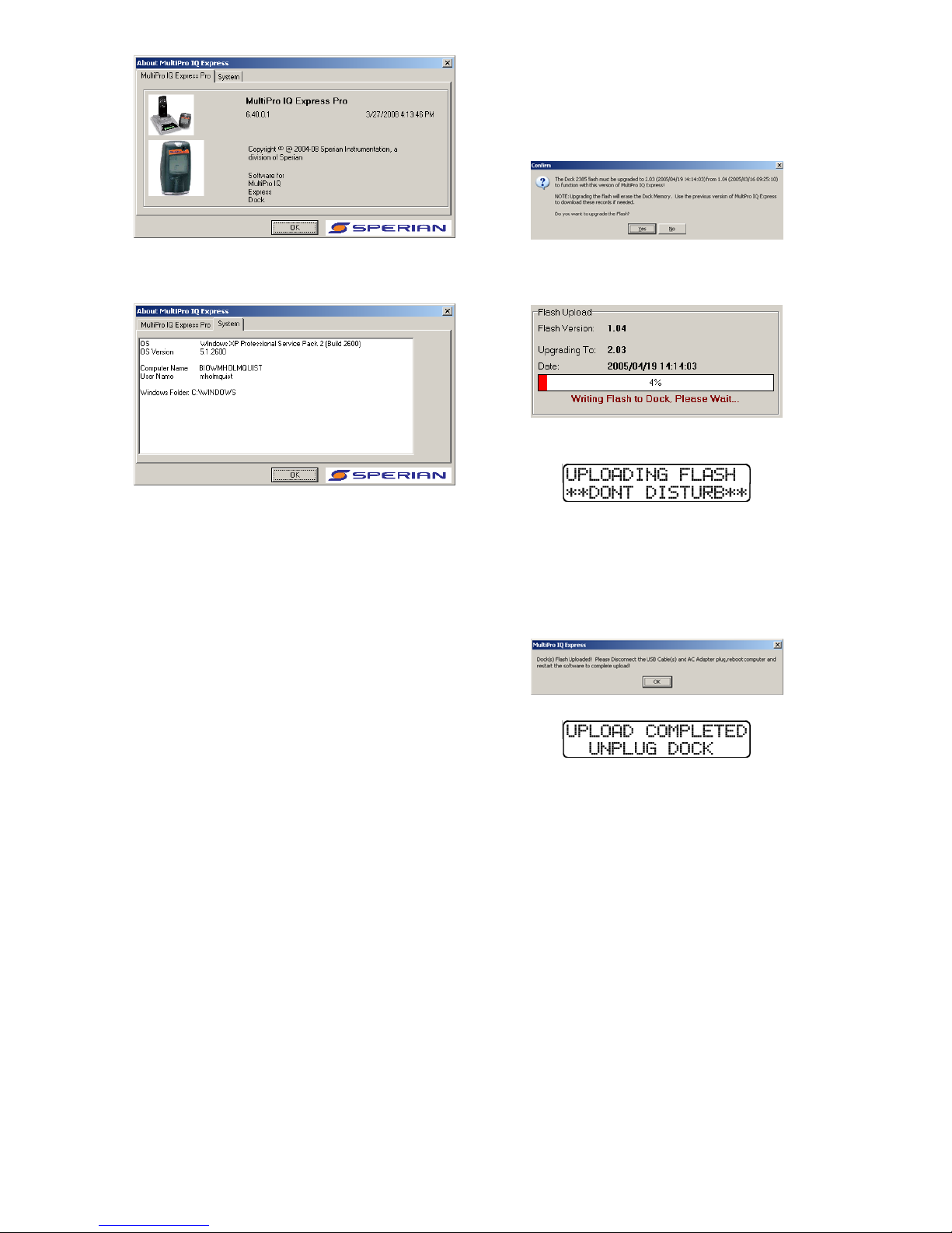
The following screen will be shown when
the PC is ready to proceed with the flash
upgrade.
The System tab contain specific
information about your PC’s operating
system.
6. Software Upgrades
Honeywell Analytics will release new
versions of MultiPro IQ Express software
from time to time. Upgrades may be
loaded onto the PC from a CD or may be
downloaded from the Internet.
To install the new version from CD, simply
place the disk in your PC’s CD-tray. The
upload will start automatically and will
immediately prompt you to install the
software.
To upload the new Flash File from the
Internet, go to the Biodownload’s Software
Downloads website at:
http://www.biodownloads.com
To upgrade the flash, download the new
flash from Biodownloads.com to the
following folder: C:\ Program Files \
Biosystems \ MultiPro IQ Express \ Dock
Flash. Then run the Flash Upload
Click Yes. The status of the upload is
shown at the far right of the screen in the
dock’s information page.
The dock will also indicate that the Flash
is being uploaded.
CAUTION Interfering with the flash
upload may result in damage to the
MultiPro IQ Express Dock.
Once the upload is completed, you’ll need
to restart the PC for the new settings to
take effect.
The dock will instruct you to unplug it.
Disconnect the MultiPro IQ Express Dock
from the PC and click OK. If an AC power
supply is being used to power the dock,
unplug it as well. Once the display on the
dock goes blank, reconnect the dock to
the PC. The AC power supply may also
be plugged back in at that time.
24
Page 26
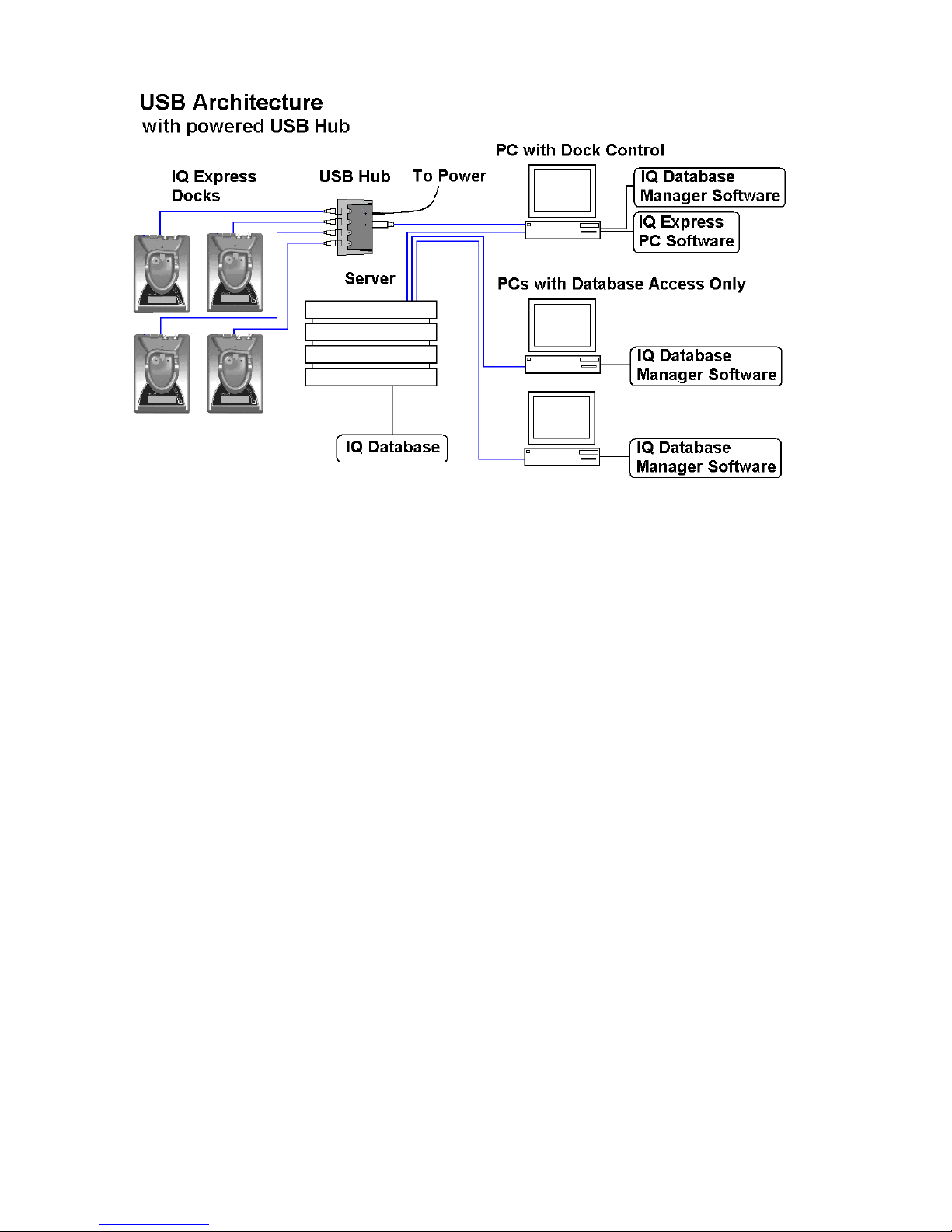
Appendix A: USB Architecture with Network Access
25
Page 27

Appendix B:
Calibration Frequency
One of the most common
questions we are asked is: “How
often should I calibrate my gas
detector?”
Sensor Reliability and Accuracy
Today’s gas sensors are designed
to provide years of reliable
service. However, there are a
number of reasons a sensor may
unexpectedly lose additional
sensitivity or even fail to respond
to gas. Such reasons include
desiccation, poisoning, physical
restriction of airflow, over
exposure, internal leakage, or
mechanical damage due to
physical shock and immersion.
Verification of Accuracy
& Related Terminology
With so many reasons why a
sensor can lose sensitivity and
given the fact that dependable
sensors are critical to survival in a
hazardous environment, frequent
verification of sensor performance
is paramount.
There is only one sure way to
verify that a sensor can respond
to the gas for which it is designed.
That is to expose it to a known
concentration of target gas and
compare the reading with the
concentration of the gas to ensure
that it is within a manufacturer’s
recommended tolerable limits.
This is referred to as a “calibration
check” or” bump test”. This test is
very simple and takes only a few
seconds to accomplish. The
safest course of action is to do
a calibration check or bump
test prior to each day’s use.
WARNING
The Canadian Standards
Association (CSA) requires the
instrument to undergo
calibration when the displayed
LEL value during a bump test
fails to fall between 100% and
120% of the expected value for
the gas.
It is not necessary to perform a
full calibration (adjustment)
unless readings for LEL and
toxic gases/vapors are outside
of the range of 90% to 120% of
the expected value. For oxygen,
the acceptable range is
considered to be ±0.5% vol., so
20.4% to 21.4% O
clean air or via application of
zero air. Further for oxygen, for
application of Honeywell
Analytics 18.0% O
gases, the reading should again
be within ±0.5% vol., so 17.5%
to 18.5% O
Lengthening the Intervals
between Calibration Checks
The MultiPro has been shipped
with a default calibration interval
of 30 days. The 30-day
calibration interval provides the
IQ Management software with
multiple sensor sensitivity
datapoints required for effective
predictive maintenance
features. If you are not using the
predictive maintenance features
in IQ Management system, or
do not wish to calibrate your
detector as often, Honeywell
Analytics recommends the
detector be calibrated at least
once every 180 days.
Honeywell Analytics
recommends a daily bump test
to ensure that the instrument is
in proper working order.
.
2
or Bump Tests
in ambient
2
balance
2
One Button Automatic
Full Calibration and
Calibration Docks
While it is only necessary to do
a calibration check or bump test
to ensure that the sensors are
working properly, all current
Honeywell, and Honeywell
Analytics gas detectors offer a
one button auto full calibration
feature. This feature allows you
to do a full calibration of a gas
detector in about the same time
as it takes to complete a
calibration check or bump test.
The use of calibration docks
can further simplify the tasks,
while automatically maintaining
electronic records of sensor
performance.
Please read also the application
note: 13-366 “Use of
‘equivalent’ calibration gas
mixtures”. This note provides
procedures to ensure safe
calibration of LEL sensors that
are subject to poisoning.
Honeywell Analytics’ website is
at
http://www.honeywellanalytics.com/.
A complete list of accessories
compatible with the MultiPro
gas detector can be found
there.
26
Page 28

Honeywell Analytics Warranty Gas Detection Products
General
Honeywell Analytics, Inc. (hereafter Honeywell Analytics) warrants gas detectors, sensors and accessories
manufactured and sold by Honeywell Analytics, to be free from defects in materials and workmanship for the
periods listed in the tables below.
Damages to any Honeywell Analytics products that result from abuse, alteration, power fluctuations including
surges and lightning strikes, incorrect voltage settings, incorrect batteries, or repair procedures not made in
accordance with the Instrument’s Reference Manual are not covered by the Honeywell Analytics warranty.
The obligation of Honeywell Analytics under this warranty is limited to the repair or replacement of components
deemed by the Honeywell Analytics Instrument Service Department to have been defective under the scope of
this standard warranty. To receive consideration for warranty repair or replacement procedures, products must
be returned with transportation and shipping charges prepaid to Honeywell Analytics or to a Honeywell Analytics
Authorized Warranty Service Center. It is necessary to obtain a return authorization number from Honeywell
Analytics prior to shipment.
THIS WARRANTY IS EXPRESSLY IN LIEU OF ANY AND ALL OTHER WARRANTIES AND
REPRESENTATIONS, EXPRESS OR IMPLIED, INCLUDING BUT NOT LIMITED TO, THE WARRANTY OF
FITNESS FOR A PARTICULAR PURPOSE. HONEYWELL ANALYTICS WILL NOT BE LIABLE FOR LOSS OR
DAMAGE OF ANY KIND CONNECTED TO THE USE OF ITS PRODUCTS OR FAILURE OF ITS PRODUCTS
TO FUNCTION OR OPERATE PROPERLY.
Instrument & Accessory Warranty Periods
Product(s) Warranty Period
PHD6
ToxiPro®, MultiPro
Battery packs and chargers, sampling pumps and
other components, which by their design are
consumed or depleted during normal operation, or
which may require periodic replacement
2 years from date of purchase
2 years from date of purchase
One year from the date of purchase
Sensor Warranty Periods
Instrument(s) Sensor Type(s) Warranty Period
O2, LEL**, CO, CO+, H2S &
PHD6, MultiPro, ToxiPro®
All Others All Sensors 1 Year
** Damage to combustible gas sensors by acute or chronic exposure to known sensor poisons such as
volatile lead (aviation gasoline additive), hydride gases such as phosphine, and volatile silicone gases emitted
from silicone caulks/sealants, silicone rubber molded products, laboratory glassware greases, spray
lubricants, heat transfer fluids, waxes & polishing compounds (neat or spray aerosols), mold release agents for
plastics injection molding operations, waterproofing formulations, vinyl & leather preservatives, and hand
lotions which may contain ingredients listed as cyclomethicone, dimethicone and polymethicone (at the
discretion of Honeywell Analytics’ Instrument Service department) void Honeywell Analytics Standard
Warranty as it applies to the replacement of combustible gas sensors.
Duo-Tox
All Other Sensors 1 Year
2 Years
27
 Loading...