

Page 1
MP953A,B,C,D
PNEUMATIC VALVE ACTUATORS
PRODUCT DATA
SPECIFICATIONS
Max. operating pressure 140 kPa
Max. safe air pressure 210 kPa
Air connection barb fitting for PE tube 6x1 or
¼ " outer diameter
See also Table 2.
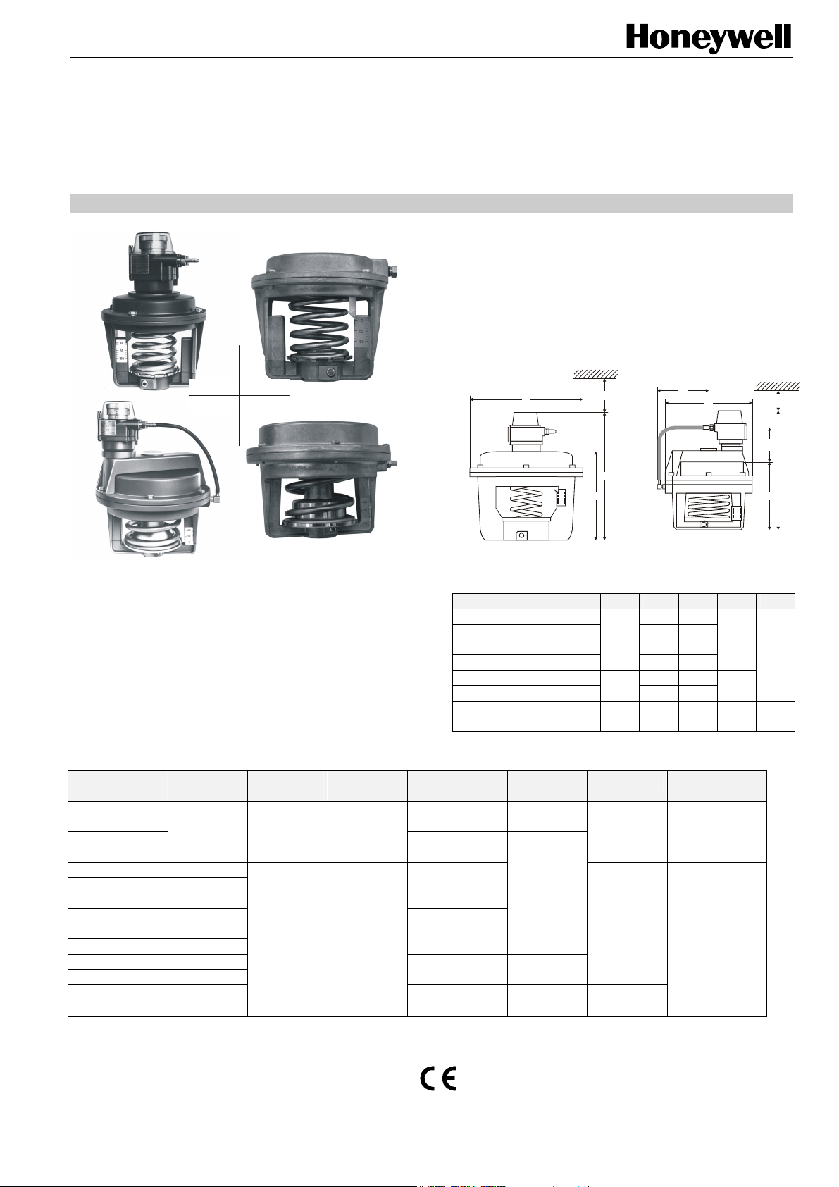
DIMENSIONS
MP953A
MP953C
MP953DMP953B
E
Fig. 1. MP953A,C (left) and MP953B,D
GENERAL
MP953 Pneumatic Valve Actuators are suitable for use in
conjunction with Honeywell valves V5011, V5013, V5015,
V5016, V5025, V5049, V5050, V5328, and V5329 to
provide proportional control of steam or hot and cold water
in HVAC systems.
Table 2. Specifications
order no.
MP953A5005 125 mm (5")
MP953A5039 200 mm (8")
MP953A5054 330 mm (13") 38
MP953B5003
MP953C5001 13.8 to 48.3
MP953C5019 55.2 to 82.8
MP953C5027 27.6 to 75.9
MP953C5068 13.8 to 48.3
MP953C5076 55.2 to 82.8
MP953C5084 27.6 to 75.9
MP953C5142 13.8 to 48.3
MP953C5159 27.6 to 75.9
MP953D5009 55.2 to 82.8
MP953D5025 27.6 to 75.9
pressure
range (kPa)
34.5 or 69 20.7 to 69 yes
adjustable
start point
-- no
positioner diaphragm Ø stroke stem action
MP953A, 125 (5") 192 -MP953C, 125 (5")
MP953A, 200 (8") 237 -MP953C, 200 (8")
MP953A, 330 (13") 327 -MP953C, 330 (13")
MP953B, 180 (7") 242 -- 107
MP953D, 180 (7")
180 mm (7") retracts
125 mm (5")
200 mm (8")
330 mm (13") 38
180 mm (7") 20 retracts
Model EØ F G H K
H
F
G
Table 1. Dimensions
130
210
343
180
20
20
extends
extends
K
E
-- 120
-- 165
-- 255
-- 137
max. operating
temperature
70 °C
120 °C
120
140
200
120
H
70
F
G
--
--
® U.S. Registered Trademark EN0B-0552GE51 R1009
Copyright © 2009 Honeywell Inc. • All rights reserved
Page 2
MP953A,B,C,D PNEUMATIC ACTUATORS
FEATURES
• Rolling diaphragm for long life and low hysteresis
• Easily attached to valve assembly
• May be installed after valve piping
• Slide lock feature permits simple engagement to valve
stem
• Models with positive-positioning relay available
ACCESSORIES
Extension Yokes
The extension yoke (see also Fig. 7) provides for extra air
circulation and less conduction of heat from the valve body to
the pneumatic actuator.
Recommended if the medium temperature in the valve body
is in the range of from 150 to 220 °C.
Table 3. Extension yokes
part no. applied to valves
43161276-001
43297431-001
V5049A DN 15…65
V5050A DN 15…80
V5025A DN 15…80 PN 25
V5016A DN 15…80
V5328A
V5329A
V5329C DN 40…80 PN 6
V5011R,S
V5013R,E
V5328A
V5329A
V5329C DN 15…32 PN 6
DN 40…80
DN 15…32 PN 16
PN 25/40
PN 16
Repair Kit Diaphragm
Table 4. Repair kit diaphragms
part no. model
R43312760-001 MP953A,C 125 (5")
R43161319-001 MP953A,C 200 (8")
R43161320-001 MP953A,C 330 (13")
R43180626-001 (diaphragm. a. sleeve MP953B,D 180 (7")
R43161322-001 (sleeve) MP953B,D 180 (7")
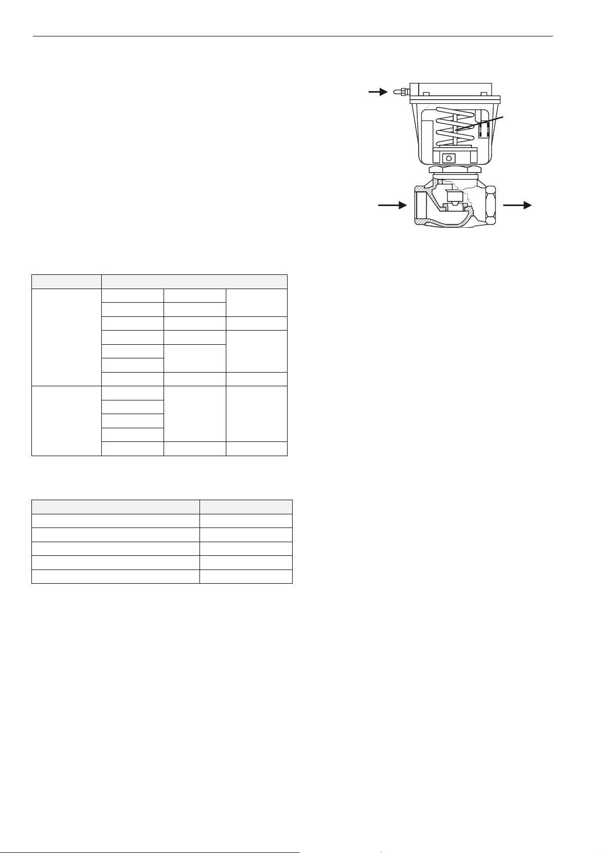
TYPICAL OPERATION
In a direct-acting (normally-open valve) system, an increase
in control air pressure will force the actuator diaphragm and
cup downward, forcing the valve stem down to proportionally
close off the flow through the valve.
Operators without the positive positioner have branch line
pressure applied to the diaphragm. Operators with positive
positioners have up to full main air pressure applied to the
diaphragm to ensure that the valve is positioned
proportionally to the branch line pressure.
control air
valve
stem
flow
Fig. 2. Typical operation
INSTALLATION
General
Ensure that the actuator has the correct size and travel to
match the valve body. Refer to the corresponding valve
product literature.
Mounting the MP953A,C (Size 5")
1. Pull the valve stem up.
2. Position the stem-locking slide so that the large hole is in
view (see also Fig. 3).
3. Set the actuator on the valve bonnet. Ensure that the stem
button passes through the hole in the stem-locking slide
and that the actuator is down flush on the shoulder of the
valve bonnet.
4. Rotate the actuator on the valve bonnet to the desired
position and tighten both actuator set screws.
5. Apply air pressure until the diaphragm cup contacts the
stem button and secure the stem button with the stemlocking slide.
Mounting the MP953A,C (Size 8" and 13")
1. If converting from smaller-size actuator, remove the
actuator by following, in reverse order, the steps outlined
in section "Mounting the MP953A,C (Size 5")".
2. Remove the stem button (see also Fig. 5).
3. Screw the stem button on the (single or double) stem
extension until it bottoms.
4. Screw the stem extension on the stem until it bottoms
(flats or locking-pin hole provided).
5. Rotate the stem extension as required to adjust dimension
"Y" as per Table 5 to the value listed, then lock the stem
extension in place by tightening the hex nut.
EN0B-0552GE51 R1009
2
Page 3
stem-locking slide
stem button
Fig. 3. Stem-locking slide
Table 5. Dimensions Y, in mm
valve size
valve series
5", 7" 8" 13"
DN
15…80 Y1
actuator size
DN
15…80 Y2
DN
100…150 Y
action
to open
3
V5016A
V5025A
89 133 190 ↑
V5328A
V5011R,S 89 133 -- ↑
V5013R,E 107 151 -V5015A -- -V5050A
V5329A,C
valve size
valve series
107 151
DN
15…65
DN
15…65
80…100
227
--
DN
↓
action
to open
V5049A 89 133 190 ↑
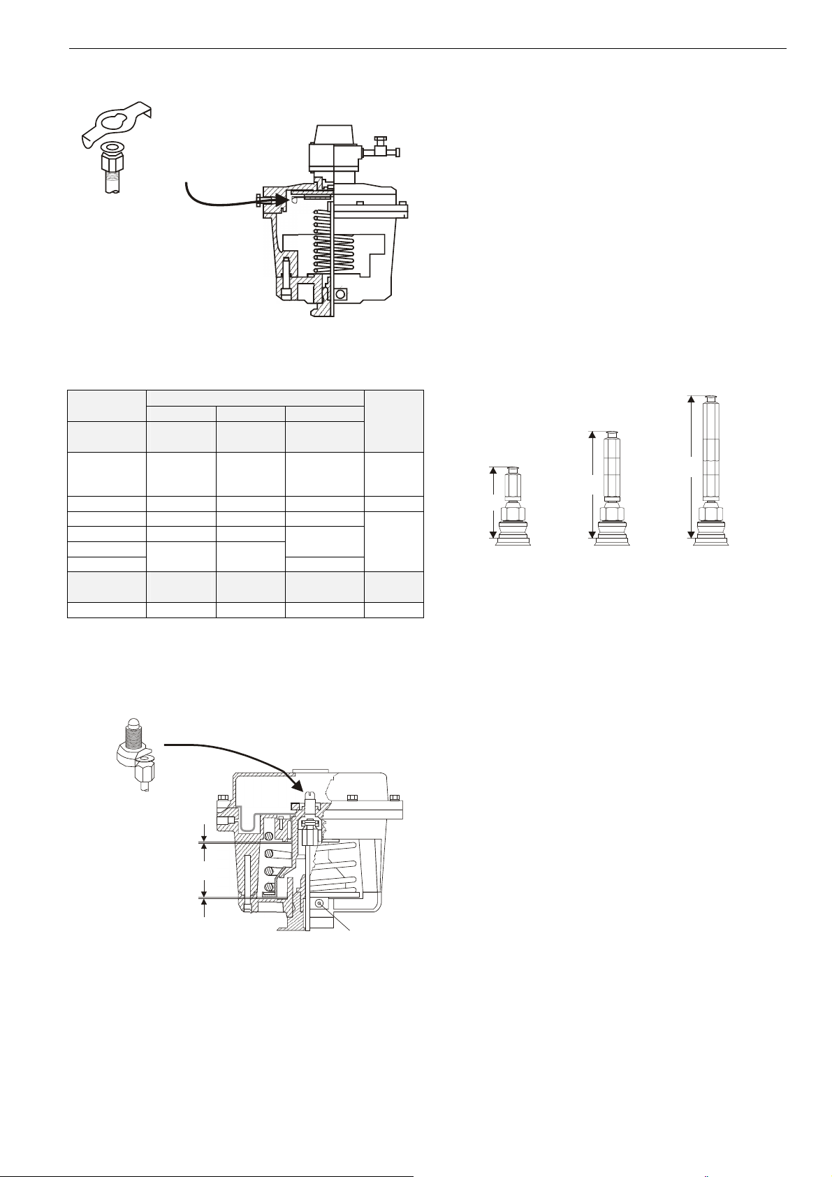
Mounting the MP953B,D
1. Pull the valve stem up.
2. Attach the stem connector screw to stem button (Fig. 4).
3. Place the actuator on the valve without pushing the stem
down.
stem button connector
clearance “B”
(measured when
spring is
compressed)
clearance “A”
MP953A,B,C,D PNEUMATIC ACTUATORS
4. Turn the stem connector screw by its screw-slot
counterclockwise to back out the stem button until the
actuator is in contact with the shoulder of the stem button.
5. Push the actuator onto the valve bonnet and hold it firmly
in place; tighten the two set screws
6. Load the stem by turning the stem connector screw
clockwise by its screw slot.
a) On a straight-through valve (position 1), turn the stem
connector screw until a clearance A of approx. 3 mm
(1/8") exists between the spring and the actuator
spider.
b) On a three-way valve, a clearance A and B of approx.
1.5 mm each is required at both ends of the stroke to
permit proper close-off. If there is no air on the
actuator, adjust the A clearance approx. 1.5 mm and
recheck the B clearance when air is available.
7. If clearances A and B cannot be adjusted following the
procedure outlined above, check the stem height "y" and
adjust, if necessary.
Y3
Y2
Y1
without stem
extension for
MP953A,C 5”
MP953B,D7”
Fig. 5. Stem extensions
with stem
extension for
MP953A,C 8”
with stem
extension for
MP953A,C 13”
ADJUSTMENTS
NOTE: Adjustments are necessary only for the
GRADUTROL-Relay used with the MP953A, B.
The range is adjusted using six adjustment screws (see also
Fig. 6). Note label on body of GRADUTROL-Relay. All
devices are factory-set for 35 kPa range. This point is adjusted by turning the adjustment knob. The graduations of the
external calibration scale on the knob present various values
within the different ranges. All devices are factory-set for
35 kPa start point. After completing the adjustment procedure, do not change the position of GRADUTROL-Relay
(with respect to the actuator).
set screw
Fig. 4. Attaching the stem connector screw
3
EN0B-0552GE51 R1009
Page 4

MP953A,B,C,D PNEUMATIC ACTUATORS
set screw
operating
range
70 kPa
(10 psi)
35 kPa
adjustment screw
(5 psi)
21 kPa
(3 psi)
Fig. 6. Adjustments of ranges and start points
Adjustment Check
1. Install a gauge in the pilot air line (P).
2. Adjust the set screw (see Fig. 6) so that travel just begins.
3. Increase pilot pressure (P) until travel is complete. If the
adjustment is correct, the gauge should read this pressure
within ±5 kPa of the start point pressure plus the range
setting.
EXAMPLE: Range setting 35 kPa start point setting 21 kPa.
The gauge should then read 56±5 kPa after the travel is
completed.
4. If the measured pressure should not be within the
permissible variation, fine adjustments must be done (if
necessary) using the start point adjustment knob.
MOUNTING WITH EXTENSION YOKE
For working temperatures of 150 to 220 °C (300 to 425 °F),
use of an extension yoke is mandatory for the MP953A,C (5"
and 8") and the MP953B,D actuators to protect the diaphragm
against excessive heat. Screw the stem extension (for the 5"
size) onto the stem, with the stem either pulled out or pushed
in (see Fig. 7), and adjust dimension "y" to the value listed in
Table 6. Lock stem extension into place by tightening the hex
nut, and attach the yoke.
Table 6. Mounting actuators with extension yoke
actuator "y" (mm) valve
MP953A,C, 5" 89
MP953B,D 107 V5013R,E, V5329A,C, V5050A
MP953A,C, 8"
133
151 V5013R,E, V5329A,C, V5050A
V5011R,S, V5328A, V5016A,
V5025A, V5049A
V5011R,S, V5328A, V5016A,
V5025A, V5049A
range adjustment start point adjustment
1
2
ALL screws “1” and “2”
tightened.
Three screws “1”
backed off to friction stop.
ALL screws “1” and “2”
backed off to friction stop.
1
1
MP953A + C5’’
MP953B + D
One graduation of scale on the start point adjustment knob represents a
start point change of 7 kPa. One complete turn of the start point
adjustment knob represents a start point change of 7 kPa.
2
One graduation of scale on the start point adjustment knob represents a
start point change of 3.5 kPa. Two complete turns of the start point
adjustment knob represent a start point change of 70 kPa.
One graduation of scale on the start point adjustment knob represents a
2
start point change of 2 kPa. Three complete turns of the start point
adjustment knob represent a start point change of 62 kPa
(note auxiliary scale).
MP953A + C8’’
V5011A
V5049A
V5328A
travel
travel
V5013A
V5049B
V5050A
V5329A,C
y
70 mm
Fig. 7. Extension yoke
y
Manufactured for and on behalf of the Environmental and Combustion Controls Division of Honeywell Technologies Sàrl, Rolle, Z.A. La Pièce 16, Switzerland by its Authorized Representative:
Automation and Control Solutions
Honeywell GmbH
Böblinger Strasse 17
71101 Schönaich
Germany
Phone: (49) 7031 63701
Fax: (49) 7031 637493
http://ecc.emea.honeywell.com
Subject to change without notice. Printed in Germany
EN0B-0552GE51 R1009
 Loading...