

Page 1
Falcon™ Edge Self-Retracting Lifelines
USER INSTRUCTION MANUAL
I361 Rev. C / MFP9720228
May 2018
Page 2

TABLE OF CONTENTS
SOMMAIRE / ÍNDICE
Product Identication and Specications ................................3
Identication du produit et spécications / Identicación y especicaciones
del producto
English ....................................................................... 4-10
EN
Français ....................................................................11-17
FR
Español .................................................................... 18-24
ES
Appendix A: Referenced Pictures ...........................................25
Annexe A: Images référencés / Apéndice A: Imágenes referenciados
Appendix B: Fall Clearance Tables
for LEADING EDGE APPLICATIONS ................................. 26-27
Annexe B: Tableaux sur la distance de chute libre pour les tâches à
proximité de bordure /
Apéndice B: Tablas de espacio libre de caída para aplicaciones de borde
avanzado
Appendix C: Fall Clearance Diagrams
for OVERHEAD APPLICATIONS ..............................................28
Annexe C: Schémas sur la distance de chute libre pour les tâches
en hauteur / Apéndice C: Diagramas de espacio libre de caída para
aplicaciones elevadas
Appendix D: Product Labels Specications .................... 29-30
Annexe D: Étiquettes sur les Produits / Apéndice D: Etiquetas de los
Productos
Appendix E: Inspection and Maintenance Log ......................31
Annexe E: Registre D’inspection et D’entretien / Apéndice E: Registro de
Inspección y Mantenimiento
Download this manual and product specication sheets at: www.millerfallprotection.com
Descargue este manual y las hojas de especicaciones del producto en: www.millerfallprotection.com
2
Téléchargez ce manuel et les ches techniques sur: www.millerfallprotection.com
Page 3
PRODUCT IDENTIFICATION
AND SPECIFICATIONS
IDENTIFICATION DU PRODUIT ET SPÉCIFICATIONS
IDENTIFICACIÓN Y ESPECIFICACIONES DEL PRODUCTO
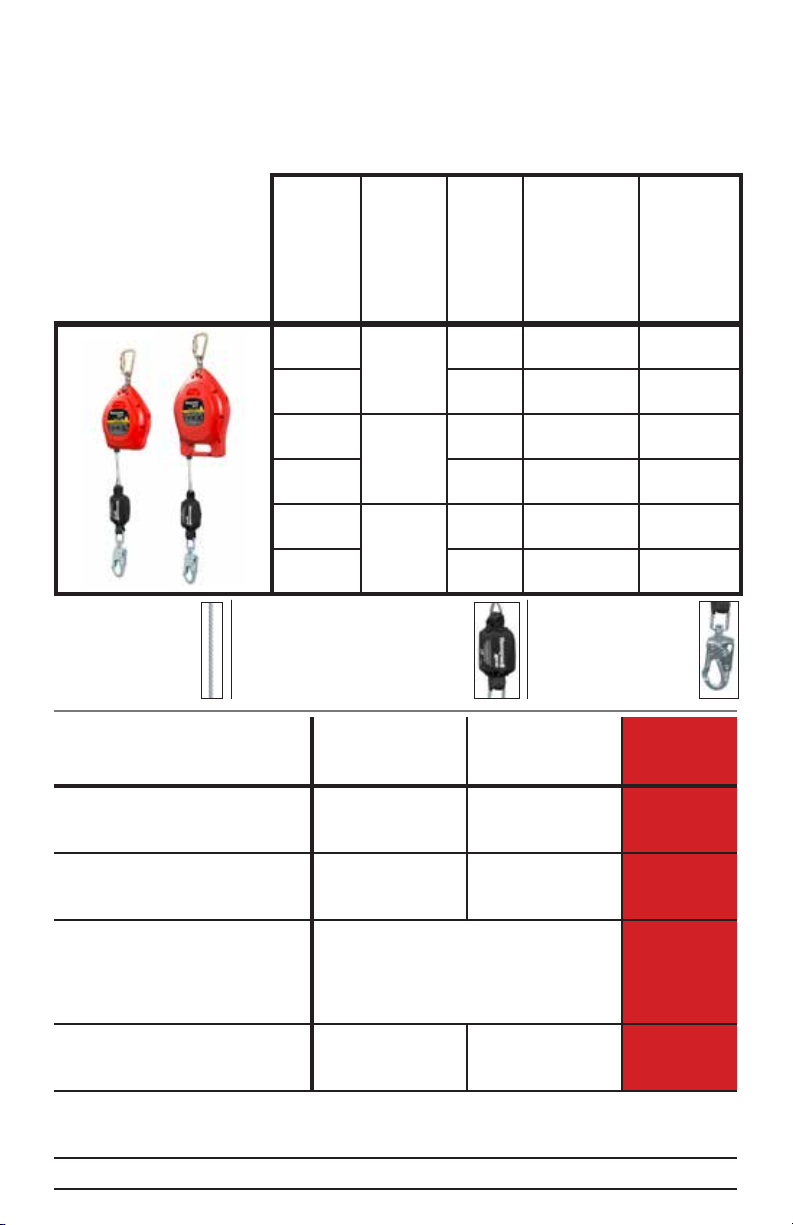
Working
Models
Modèles
Modelos
MP30G-LE
MP50G-LE
MP20G-LE
MP20G-LEK
MP30G-LE
MP30G-LEK
MP50G-LE
MP50G-LEK
Ballistic Nylon
Nylon Ballistic / Nylon Ballistic
CarbonX Flame Retardant Fabric
CarbonX Tissu ignifugé / CarbonX
Tela de retardante de llama
FALCON EDGE
MP20G-LE
Galvanized Steel
Acier galvanisé
Acero galvanizado
Performance Specications
Spécications de performance
Especicaciones de rendimiento
Capacity*
Capacité
Capacidad
Approved for Sharp Edge
Approuvé pour bordure à angle vif
Aprobado para borde alado
Max Arrest Distance**
Distance D’Arret Max
Distancia De Detención Máx
Max Arrest Force
Force D’Arret De Chute Max
*Includes body weight, clothing and tools; if the system is used by an employee having a combined tool and body weight greater than 310 lbs. (140.6
kg), then the employer must appropriately modify the criteria and protocols to provide proper protection for such heavier weights, or the system will
not be deemed to be in compliance with the requirements of OSHA 1926.502(d)(16). [ANSI capacity range is 130 lbs.- 310 lbs. (59kg-140.6kg)].
**Overhead use / Usage aérien / Aplicaciones elevadas. ***For a 170 kg (375 lb) user, deployment is equal to 1.25 times free fall distance, h, or 1.2 m
(47 in), whichever is greater.
Refer to variable label for unit compliances. / Prière de se reporter à l’étiquette variable pour les conformités d’unités. / Consulte la etiqueta variable
para ver el cumplimiento de normas de la unidad.
Fuerza De Frenado Máx
Length
Longueur
de travail
Longitud
de trabajo
20 ft.
(6m)
30 ft.
(9m)
50 ft.
(15m)
OSHA
1926.502
& 1910.66
90-420 lbs
(40.8-190.5kg)
R ≥ 0.005 in
(0.13mm)
42 in (1.1m) for 20 ft and 30 ft models;
42 po (1,1m) pour les modèles de 20 pi et de 30 pi;
42 pulgadas (1,1m) para modelos de 20 pies y 30 pies;
54 in (1.4m) for 50 ft models
54 po (1,4m) pour les modèles de 50 pi
54 pulgadas (1,4m) para modelos de 50 pies
1,800 lbf
(8kN)
Material
Matériel
de lin de
sécurité
Material de
cuerda de
seguridad
ANSI Z359.14
Class B & LE
[Average / Moyenne /
Promedio 900 lbf (4kN)]
Lifeline
Shock
Absorber
Cover
Boîtier de
l’amortisseur
Funda del
absorbedor de
impacto
Steel Snap Hook
Crochet mousqueton
en acier / Gancho de
cierre rápido de acero
130-310 lbs
(59-140.6kg)
R ≥ 0.005 in
(0.13mm)
1,800 lbf (8kN)
Lifeline
Connector
Connecteur
de lin de
sécurité
Conector de
cuerda de
seguridad
CSA
Z259.2.2-17
Class SRL-LE
90-375 lbs
(41-170kg)
R ≥ 0.010 in
(0.25mm)
***
1,800 lbf
(8kN)
3
Page 4

EN
INSTRUCTIONS FOR USE
Personal Protective Equipment
LEADING EDGE
SELF-RETRACTING
LIFELINES
Thank you for your purchase of Honeywell
Miller fall protection equipment manufactured
by Honeywell Industrial Safety.
WARNING
All persons using this equipment
must read, understand and follow all
instructions. Failure to do so may result
in serious injury or death. Do not use
this equipment unless you are properly
trained.
It is crucial that the authorized person/user
of this equipment read and understand these
instructions. In addition, federal law requires
employers to ensure that all users are trained
in the proper installation, use, inspection, and
maintenance of fall protection equipment. Fall
protection training should be an integral part
of a comprehensive safety program.
Proper use of fall arrest systems can save
lives and reduce the potential of serious
injuries from a fall. The user must be aware
that forces experienced during the arrest of a
fall or prolonged suspension may cause bodily
injury. Consult a physician if there is any
question about the user’s ability to use this
product. Pregnant women and minor children
must not use this product.
1.0 Purpose
Self-retracting lifelines are self-contained
retractable devices designed to be used
by personnel in applications where fall
protection in combination with unrestricted
worker mobility is needed. Honeywell Miller
Falcon Edge Self-Retracting Lifelines are
specially-engineered retractable units with
unique features designed for leading edge
applications as well as overhead applications.
4
2.0 General Fall Protection
Requirements
2.1 General Requirements
All warnings and instructions shall be provided
to authorized persons/users.
All authorized persons/users must
reference the regulations governing
occupational safety, as well as applicable
ANSI or CSA standards. Please refer
to product labeling for information on
specic OSHA regulations, and ANSI and
CSA standards met by product.
Proper precautions should always be taken to
remove any obstructions, debris, material, or
other recognized hazards from the work area
that could cause injuries or interfere with the
operation of the system.
Always check for obstructions below the work
area to make sure potential fall path is clear.
Allow adequate fall clearance below the work
surface.
To minimize the potential for accidental
disengagement, a competent person must
ensure system compatibility.
All equipment must be inspected before
each use according to the manufacturer’s
instructions. Additionally, equipment must be
inspected by a competent person, other than
the user, on a regular basis, at least annually.
Any product exhibiting deformities, unusual
wear, or deterioration must be immediately
discarded in such a manner as to prevent
inadvertent further use.
Any equipment subject to a fall must be
removed from service.
The authorized person/user shall have
a rescue plan and the means at hand to
implement it when using this equipment.
Equipment must not be altered in any way.
Do not lubricate or attempt to repair this
device. Repairs must be performed only
by the manufacturer, or persons or entities
authorized in writing by the manufacturer.
Never use fall protection equipment for
purposes other than those for which it was
designed. Fall protection equipment should
never be used for towing or hoisting.
Page 5

Environmental hazards should be considered
when selecting fall protection equipment.
Equipment must not be exposed to chemicals,
heat, ames, or other environmental conditions
which may produce a harmful effect. Use in
a corrosive or caustic environment dictates
a more frequent inspection and servicing
program to ensure the integrity of the device
is maintained.
All synthetic material must be protected from
slag, hot sparks, open ames, or other heat
sources. The use of heat resistant materials is
recommended in these applications.
Do not allow equipment to come in contact
with anything that will damage it including,
but not limited to, abrasive, rough or hightemperature surfaces, heat sources, electrical
hazards, or moving machinery.
Do not expose the equipment to any hazard
which it is not designed to withstand. Consult
the manufacturer in cases of doubt.
Never remove product labels, which include
important warnings and information for the
authorized person/user.
2.2 Warnings and Limitations
Capacity
For use by ONE person only. Refer to the
product labels and to Product Identication
and Specications in this manual for the
minimum and maximum weight capacities.
Anchorage Requirements
Honeywell recommends that all anchorages
be:
• Capable of supporting 5,000 lbs (22.2 kN)
per worker attached; OR
• Designed, installed, and used, under the
supervision of a qualied person, as part of
a complete personal fall protection system
that maintains a safety factor of at least two.
Always refer to applicable national and
regional fall protection regulations and
standards to ensure compliance.
Limits of Use
Self-retracting lifelines (SRLs) are designed
for fall arrest applications only. Never use
an SRL as a restraint or positioning device.
IMPORTANT!
A fall restraint scenario could occur
anytime:
• the user fully extends the lifeline and
applies weight or stress to that lifeline;
• the user intentionally or unintentionally
locks up the lifeline, without the lifeline
fully extended, and applies weight or
stress to that lifeline.
The correct application for using an
SRL allows the user to be connected
and move freely to perform the required
work tasks without locking the lifeline
or applying tension on the lifeline at full
extension.
System Compatibility
Honeywell Miller fall protection products are
designed for use with Honeywell-approved
components only. Substitution or replacement
with non-approved component combinations or
subsystems or both may affect or interfere with
the safe function of each other and endanger
the compatibility within the system. This
incompatibility may affect the reliability and
safety of the total system.
WARNING
Always refer to the regulations and
standards regarding personal fall
arrest system component requirements
and the instructions provided with each
component being used as part of the
personal fall arrest system.
Falcon Edge Self-Retracting Lifelines
are approved for overhead and leading
edge applications. For the purposes of
this instruction manual, a leading edge
application is one whereby the user may
be anchored at foot level/working surface
or higher and the lifeline has the potential
to come in contact with an edge if the user
falls. It is recommended to anchor device
vertically overhead whenever possible. For
the purposes of this instruction manual,
an overhead application implies that there
is no slack in the lifeline when the unit is
mounted above the user and connected to
the user’s back D-ring.
5
Page 6

Falcon Edge Self-Retracting Lifelines
may be used with Honeywell-approved
horizontal lifeline systems with special
considerations. The retractable must
be capable of traveling well along the
length of the lifeline and should remain
perpedicular to the worker throughout the
course of work. It is recommended that
an on-site qualied person evaluate the
conditions before installation and use of
the retractable with the horizontal lifeline
system. In addition, always refer to the
instructions provided with the horizontal
lifeline system to ensure compatibility of
the self-retracting lifeline with the system.
This device shall be installed and used in
such a manner as to minimize the potential
for a swing fall. User must never be
exposed to a swing fall hazard.
Do not allow lifeline to become slack.
3.0 Installation/Use
WARNING
All Honeywell Miller Self-Retracting
Lifelines must be inspected and tested
for locking and retraction before each
use (see 6.0 Inspection & Maintenance).
Special Requirements, Warnings &
Limitations pertaining to All Leading
Edge Applications
• The anchor point must be at the same
height or higher than the edge at which a
fall might occur.
• The allowable angle of redirection of
the lifeline portion of the device at the
edge over which a fall might occur (as
measured between the two sides formed
by the redirected lanyard) shall be at
least 90 degrees.
• The potential for a swing fall must
be minimized for worker and lifeline
protection. The worker must never work
on the far side of an opening, opposite
the anchor point.
• Falcon Edge Self-Retracting Lifelines are
specically designed to reduce forces to
both the worker and lifeline connection
that extends beyond a leading edge.
• Applications for leading edge retractables
include steel decking, concrete and
wood surfaces. Despite the wide range of
applications for these units, surfaces in
contact with the equipment must still be
evaluated by a qualied person in regards
to creating premature wear and/or failure
due to excessive abrasion or cutting of
materials.
The installer of the SRL must not be
exposed to a fall hazard while mounting
the unit.
IMPORTANT!
Overhead mounting of a self-retracting
lifeline is typically recommended.
However, Falcon Edge Self-Retracting
Lifelines have been specically designed
and successfully tested in accordance
with the standards for
falls over a sharp edge (radius ≥ .005 in
(.13mm)).
6
horizontal use and
Special Anchorage Requirements for
Leading Edge Applications
Honeywell Industrial Safety approves a
connection height at foot level/working surface
or higher for Falcon Edge Self-Retracting
Lifelines. Minimum set-back distance is
18 in. (0.5m). Lateral edge distance (work
zone) from perpendicular to the anchor
point is dependent on set-back distance of
anchor point (see DIAGRAMS A & B and Fall
Clearance Tables in APPENDIX B).
IMPORTANT!
A Falcon Edge unit anchored at a setback distance of 25 ft. (7.62m) with a
user working at the maximum permitted
lateral edge distance (work zone) of 25
ft. (7.62m) will experience the greatest
swing fall allowed for a Falcon leading
edge application. It is imperative that
swing fall be limited as much as possible.
This can be accomplished by increasing
the set-back distance and/or limiting the
work zone. A swing fall hazard must not
exist in the path of the potential swing
fall.
Page 7

3.1 Falcon Edge
Connecon Height
Edge SetbackDistance
VercalSwing Fall
Lateral Swing Fall
30˚
30˚
30˚
30˚
Self-Retracting Lifelines
REFERENCED PICTURES ARE
LOCATED IN APPENDIX A ON
PAGE 25.
3.1.2 Connection to Harness
1) Connect the lifeline end connector to the
harness back D-ring (see Fig. 2). Make sure
that the connector is completely closed and
locked.
4.0 Fall Clearance
3.1.1 Installation to Anchorage
1) Locate an approved anchorage following
all general anchorage requirements as well as
the additional requirements for leading edge
applications found in 3.0. If an anchorage
connector is used, make sure it is compatible
with the anchorage and the device connector
(carabiner) in regards to strength, size, and
shape. Follow all instructions provided with the
anchorage connector.
2) Connect the body of the self-retracting
lifeline to the anchorage (or anchorage
connector, if applicable) using the device
connector (carabiner) (see Fig. 1). Make sure
that the connector is completely closed and
locked and that its gate is not in a position to
be load-bearing.
DIAGRAM A - LEADING EDGE APPLICATION
Connection
Height
Set-Back
Edge
Distance
Max Fall Arrest
Distance
+ Swing Fall
4.1 Calculating Fall
Clearance Required for
LEADING EDGE APPLICATIONS
When a Falcon Edge Self-Retracting
Lifeline is used in a leading edge
application, use the Fall Clearance
Tables in APPENDIX B on pages 2627 to determine minimum required fall
clearance.
Anchor Point
Work Radius
Lateral Edge
Distance
Swing Fall
IMPORTANT!
Max
DIAGRAM B - OVERHEAD VIEW OF LEADING EDGE APPLICATION
≤25 ft.
(7.62m)
Anchor Point
≤25 ft.
(7.62m)
Edge
Refer to Fall Clearance Tables
in APPENDIX B for lateral edge distance
(work zone) limitations with regard to
specied set-back distances of anchor point.
7
Page 8
4.2 Calculating Fall
Clearance Required for
OVERHEAD APPLICATIONS
STOP!
This section only applies when using
a Falcon Edge Self-Retracting Lifeline
in an overhead application. For leading
edge applications, refer to Fall Clearance
Tables in APPENDIX B.
It is essential to understand how to
calculate the fall clearance distance
required for each work application to avoid
contact with a lower level.
The basic calculation shown below and the
related diagrams in Appendix C on page
28 may be used to determine Required
Fall Clearance when using a self-retracting
lifeline in an overhead application. For a
more automated approach to calculating
Required Fall Clearance, access the Miller
Fall Clearance Calculator online:
www.millerfallprotection.com/fallclearance.
SELF-RETRACTING LIFELINE
FALL CLEARANCE CALCULATION
FOR OVERHEAD APPLICATIONS
(see Appendix C: Diagram 1)
[Calculation taken from work level]
Maximum Arrest Distance (MAD)
+ [Non-Standing Work Position Factor (NSF)]
+ [Swing Fall Factor (SFF)]
+ 2.5 ft. (0.8m) Safety Factor (SF)
= Required Fall Clearance (RFC)
CAUTION: Read all notes and refer to all
self-retracting lifeline fall clearance diagrams
and labels to determine exact required fall
clearance for your application.
IMPORTANT NOTES:
Self-retracting lifelines must be anchored
overhead to ensure the accuracy of the fall
clearance calculation and related information.
It is important to understand that other factors,
such as whether the user is performing work
in a standing, crouched or lying down position
and/or whether the user is working directly
below the anchor point or at an angle, can affect
fall distance when using a retractable device.
The self-retracting lifeline fall clearance
calculation assumes the user is standing. If
the user will be performing work in a crouched
or kneeling position, an additional 3 ft. (0.9m)
of fall clearance is required (see Diagram 2).
If the user will be performing work in a lying
down position, an additional 5 ft. (1.5m) of fall
clearance is required.
The self-retracting lifeline fall clearance
calculation also assumes the user is working
directly below the anchor point, minimizing
any possibility for a swing fall. In a swing
fall situation, the total fall distance will be
greater than if the user were working directly
below the anchor point (see Diagram 3). In
some applications, it may not be possible
to work directly below the anchor point. In
such a case, the worker must increase the fall
clearance distance to account for the swing
fall factor. In any case, the worker must not
be exposed to a potential swing fall where
contact with another object may occur (see
Diagram 4).
The maximum arrest distance [free fall (FF) +
deceleration (D)] varies by retractable. Always
refer to the labels on the specic unit to
determine the maximum arrest distance.
If there is any question about
calculating fall clearance distance,
please contact Honeywell Technical Service:
1-800-873-5242 (press 4)
TABLE 1: Minimum Required Fall Clearances - OVERHEAD APPLICATIONS ONLY
Minimum Required Fall Clearance from Work Level to Lower Level*
Working Directly
Below Anchor Point
Maximum
Arrest Distance
of SRL
42 in (1.1m)
54 in (1.4m)
*This chart shows general minimum fall clearances required for an overhead application. An exact calculation, based on the SRL
to be used and an assessment of the work site and conditions that may affect the worker’s fall clearance, must be performed.
In Standing
Position
6 ft (1.8m) 9 ft (2.7m) 11 ft (3.4m)
7 ft (2.1m) 10 ft (3m) 12 ft (3.7m)
In Kneeling/
Crouched
Position
In Lying Down
Position
NOT Working Directly
Below Anchor Point
In Potential
Swing Fall Position
Varies - Additional Fall
Clearance Required
8
Page 9

5.0 Inspection and
Maintenance
5.1 Inspection and Operation
Testing
Honeywell’s inspection requirements incorporate
the criteria established by current safety
standards. The inspection criteria for the
equipment shall be set by the user’s organization,
such that it equals or exceeds the criteria
required by the manufacturer and the standards
with which the organization elects to comply.
Equipment shall be thoroughly inspected
and operationally tested by the user before
each use, and additionally, by a competent
person, other than the user, at least annually
(or semi-annually per ANSI A10.32) for:
[*ANSI Z359.14 and CSA Z259.2.2-17 provide
additional inspection requirements based on type
of use and conditions of use. Refer to Table 2 for
compliance with these standards. (*See note in 6.2
Maintenance.)]
Absence or illegibility of markings/labels.
Absence of any elements affecting the
equipment form, t or function.
Evidence of defects in or damage to the
cable lifeline including cuts, broken strands,
corrosion, kinks, chemical attack, abrasion,
alteration, excessive aging, and excessive wear.
CAUTION: Always wear gloves when
inspecting cable lifelines; broken strands
can cause injury!
Operational damage to the lifeline.
Retraction - With the device in a mounted
position, test the lifeline retraction and tension
by pulling out several feet of the lifeline and allow
to retract back into the unit. Always maintain
a light tension on the lifeline as it retracts. The
lifeline should pull out freely and retract all the
way back into the unit. If the lifeline does not
pull out smoothly or sticks when retracting, pull
all the lifeline out of the housing and allow it to
retract slowly under tension. Do not use the unit
if the lifeline does not retract properly.
CAUTION: Do not let go of the lifeline and
let it retract on its own; always maintain
tension while it retracts!
Lockup Mechanism - The braking mechanism
can be tested by grasping the lifeline and
applying a sharp steady pull downward which
will engage the brakes. There should be no
slippage of the lifeline while the brakes are
engaged. Once tension is released, the brakes
will disengage and the unit will return to the
retractable mode.
Evidence of defects in or damage to
hardware elements including cracks, breaks,
rough or sharp edges, deformation, corrosion,
chemical attack, excessive heating, pitted
surfaces, alteration, and excessive wear.
TABLE 2: ANSI Z359.14 and CSA Z259.2.2-17: Inspection Requirements
Type of
Use
Infrequent
to Light
Moderate
to Heavy
Severe to
Continuous
Notes:
1) Failure of a worker to perform “before each use” inspection or failure of an inspection by a worker shall
initiate the requirement for inspection by a competent person.
2) Failure of a competent person to perform inspections as specied in this Table, or failure of an inspection by
the competent person shall initiate product revalidation or disposal.
3) Determination of the type of use category shall be determined by a competent person.
4) A SRD that is considered non-repairable, or not designed for disassembly such that internal inspection is not
possible without rendering it unserviceable, is not subject to revalidation inspection. These SRD’s shall have
service life and other inspection requirements as provided by the manufacturer’s instructions.
Application
Examples
Rescue & conned space,
factory
maintenance
Transportation,
residential
construction,
utilities, ware-
house
Commercial
construction,
oil & gas,
mining
Conditions of Use
Good storage conditions,
indoor or infrequent outdoor
use, room temperature,
clean environments
Fair storage conditions, indoor and extended outdoor
use, all temperatures, clean
or dusty environments
Harsh storage conditions,
prolonged or continuous out-
door use, all temperatures,
dirty environment
Worker
Inspection
Frequency
Before each
use
Before each
use
Before each
use
Competent
Person
Inspection
Frequency
Annually At least every 5
Semi-
annually to
annually
Quarterly
to semiannually
APPLIES TO CSA
ONLY
Product Revalida-
tion Frequency
years but not more
than intervals
required by the
manufacturer
At least every 2
years but not more
than intervals
required by the
manufacturer
At least annually
but not more than
intervals required by
the manufacturer
9
Page 10
Operational damage to the hardware.
Snap Hook/Carabiner - The connector
gate (keeper) should seat into the nose
without binding and should not be distorted
or obstructed. The gate spring should exert
sufcient force to rmly close the gate. The
gate locking mechanism must prevent the gate
from opening when closed. It is permissable to
lubricate snap hooks and carabiners if needed.
Evidence of defects in or damage to the
housing and/or loose/missing fasteners.
Evidence of defects in or damage to
shock absorber pack including holes, tears,
deterioration, loose or broken stitching.
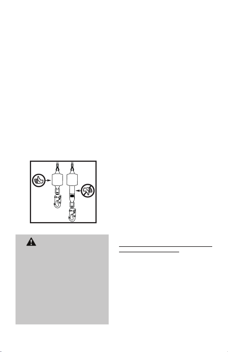
Evidence of deployed or activated fall load
indicators.
Falcon Edge Self-Retracting Lifelines are
equipped with a load indicator built into the
shock absorber pack. When subjected to
fall arrest forces the internal white energy
absorber will become exposed or deploy as
shown.
5.2 Maintenance
Basic care of all fall protection equipment
will prolong its service life and will contribute
toward the performance of its vital safety
function.
Servicing
Servicing of Honeywell Miller self-retracting
lifelines must only be carried out by Honeywell
Industrial Safety or persons or entities
authorized in writing by Honeywell. A record
log of all servicing and inspection dates for
this device must be maintained. Only original
Honeywell replacement parts are approved
for use in this device. Contact your Honeywell
distributor or call Honeywell Technical Service
at 1-800-873-5242 for a return authorization
number.
Honeywell Miller self-retracting lifelines
require no annual factory recertication.*
*Honeywell, as the manufacturer, does not
require annual factory recertication for
Honeywell Miller self-retracting lifelines.
Ultimately, however, the end-user/company
must ensure compliance with applicable
national and regional fall protection
regulations and may elect to follow additional
voluntary standards with regard to inspection
and recertication requirements.
WARNING
When inspection and operational
testing reveals defects in or damage to
equipment, inadequate maintenance of
equipment, or evidence of equipment
having been exposed to fall arrest forces
or loading, the equipment shall be
immediately removed from service.
Falcon Edge Self-Retracting Lifelines
are repairable devices. Units removed
from service, shall be marked and
tagged “UNUSABLE” and returned
for service in accordance with the
manufacturer’s instructions.
10
Cleaning and Storage
This device must be kept clean and free of
contaminants. Periodically clean the exterior
of the device and wipe the lifeline using a
damp cloth and mild detergent.
When not in use, equipment shall be stored
in a manner as to preclude damage from
environmental factors, such as temperature,
light, UV, excessive moisture, oil, chemicals
and their vapors, or other degrading elements.
The lifeline should be fully retracted into
the device when not in use.
Page 11

FR
MODE D’EMPLOI
Équipements de protection
individuelle
LEADING EDGE
SELF-RETRACTING
LIFELINES
Nous vous remercions pour votre achat
d’équipement de protection contre les chutes
Honeywell Miller fabriqué par Honeywell
Industrial Safety.
AVERTISSEMENT
Toutes les personnes utilisant cet
équipement doivent lire, comprendre et
observer l’intégralité des instructions.
Le non-respect de cette consigne peut
entraîner des blessures, ou même le
décès. N’utilisez cet équipement que si
vous avez été correctement formé.
Il est essentiel que la personne autorisée à
utiliser cet équipement de protection contre
les chutes lise et comprenne ces instructions.
De plus, la loi fédérale oblige les employeurs
à s’assurer que tous les utilisateurs ont reçu
une formation sur la manière appropriée
d’installer, d’utiliser, d’inspecter et d’entretenir
les équipements antichute. La formation sur la
protection contre les chutes devrait faire partie
intégrante d’un programme global de sécurité.
L’utilisation adéquate de systèmes d’arrêt
de chute peut épargner des vies et réduire
le risque de blessures graves consécutives
à une chute. L’utilisateur doit être sensibilisé
au fait que les forces subies lors d’un arrêt de
chute ou d’une suspension prolongée peuvent
causer des blessures corporelles. Dans
l’incertitude sur la capacité de la personne à
utiliser ce produit, consulter un médecin. Les
femmes enceintes et les mineurs ne doivent
pas utiliser ce produit.
1.0 Objet
Les lins de sécurité autorétractables sont
des dispositifs rétractables conçus pour être
utilisés par le personnel lorsqu’une protection
antichute n’entravant pas la mobilité de
l’ouvrier est nécessaire pour réaliser leur
travail. Les lins de sécurité autorétractables
à proximité de bordure Falcon de Honeywell
Miller sont des dispositifs rétractables de
conception spéciale qui présentent des
caractéristiques uniques destinées aux
tâches près des bordures ainsi que pour des
utilisation suspendues.
2.0 Exigences générales de
protection contre les chutes
2.1 Exigences Générales
Les avertissements et instructions devront
être mis à la disposition des personnes/
utilisateurs autorisés.
Les personnes/utilisateurs autorisés doivent
se reporter à la réglementation applicable en
matière de sécurité en milieu de travail, ainsi
qu’aux normes ANSI ou CSA pertinentes.
Veuillez vous reporter aux étiquettes apposées
sur les produits pour des informations plus
détaillées sur les règlements OSHA, ainsi
que les normes ANSI et CSA auxquelles ces
produits sont conformes.
Des précautions doivent être prises an
d’éliminer de la zone de travail les obstacles,
débris, matériaux ou autres éléments
présentant un danger et qui pourraient causer
des blessures ou nuire au bon fonctionnement
du système.
Toujours vérier qu’il n’y a pas d’obstacles en
dessous de la zone de travail et que le trajet
en cas de chute est dégagé.
Prévoir une distance de dégagement
sufsante en dessous de la surface de travail.
Pour minimiser le risque de décrochage
accidentel, une personne compétente doit
s’assurer de la compatibilité du système.
L’ensemble de l’équipement doit être inspecté
avant chaque utilisation conformément aux
instructions du fabricant. En outre, l’équipement
doit être inspecté par une personne
compétente, autre que l’utilisateur, sur une
base régulière, au moins annuellement.
Tout produit présentant des déformations,
usure inhabituelle ou détérioration doit être
immédiatement jeté dans une telle manière à
empêcher l’utilisation par inadvertance.
Tout équipement soumis à une chute doit être
mis hors service.
L’utilisateur doit posséder un plan de
sauvetage et avoir les moyens de le mettre en
œuvre lorsqu’il utilise cet équipement.
Il est interdit de modier l’équipement, de
quelque façon que ce soit. Ne lubriez ou tenter
de réparer ce dispositif. Les réparations doivent
être effectuées uniquement par le fabricant de
l’équipement, ou par des personnes ou entités
autorisées par écrit par le fabricant.
11
Page 12

Ne jamais utiliser un équipement de protection
contre les chutes dans un but autre que celui
pour lequel il a été prévu. Ne jamais utiliser un
tel équipement pour remorquer ou lever une
charge.
Dans la sélection d’équipement de protection
contre les chutes, on doit tenir compte des
risques environnementaux. Les équipements
ne doivent pas être exposés aux dangers
environnementaux ni aux produits chimiques
qui peuvent produire un effet nocif. Pour
utiliser l’équipement dans des environnements
hautement corrosifs ou caustiques, il faut
mettre en place un programme d’inspection
et d’entretien à intervalles rapprochés pour
maintenir l’intégrité du dispositif.
Les matériaux synthétiques doivent être
protégés contre le laitier (de soudure), les
étincelles chaudes, les ammes nues ou
autres sources de chaleur. Dans de tels cas,
on recommande d’utiliser des matériaux
résistant à la chaleur.
Ne pas laisser l’équipement venir en
contact avec quoi que ce soit qui pourrait
l’endommager, comprenant (sans y être
limité) : les surfaces rugueuses, abrasives ou
chaudes, les sources de chaleur, les dangers
électriques ou les pièces mobiles.
Ne pas exposer les équipements aux dangers
pour lesquels ils n’ont pas été conçus. En cas
de doute, consulter le fabricant.
Ne jamais ôter une étiquette apposée sur un
produit; des informations et avertissements
importants y sont en effet inscrits à l’intention de
la personne/de l’utilisateur autorisé.
2.2 Avertissements et Limitations
Capacité
Pour utilisation par UNE seule personne.
Pour connaître la capacité de charge
minimale et la capacité de charge
maximale, se reporter aux étiquettes de
produit et à la section « Identication du
produit et spécications » du présent
manuel.
Compatibilité du Système
Honeywell Miller produits de protection
contre les chutes sont conçus pour être
utilisés avec des composants approuvés par
Honeywell seulement. Les substitutions ou
les remplacements par des combinaisons
de composants ou de sous-systèmes non
approuvés peuvent nuire à leur sécurité de
fonctionnement réciproque et ainsi remettre en
cause la compatibilité des éléments du système.
Cette incompatibilité peut nuire à la sécurité et à
la abilité de l’ensemble du système.
12
AVERTISSEMENT
Toujours se référer aux normes et
règlements relatifs aux composants
formant le système d’arrêt de chute,
ainsi qu’aux instructions fournies
avec chaque composant utilisé dans le
système d’arrêt de chute individuel.
Exigences relatives aux
ancrages
Honeywell recommande que tous les ancrages
soient:
• Capable de supporter 5 000 lb (22,2 kN) par
travailleur attaché; OU
• Conçu, installé et utilisé, sous la supervision
d’une personne qualiée, dans le cadre d’un
système complet de protection contre les
chutes qui maintient un facteur de sécurité
d’au moins deux.
Toujours se référer aux réglementations et aux
normes nationales et régionales en matière de
protection contre les chutes applicables pour
assurer la conformité.
Limites d’utilisation
Les câbles de sécurité autorétractables
sont conçus pour arrêter les chutes
seulement. N’utilisez jamais un câble de
sécurité autorétractable comme dispositif
de retenue ou de positionnement.
REMARQUE IMPORTANTE!
Un scénario de retenue antichute peut se
produire à tout moment :
• l’utilisateur déploie complètement
le câble de sécurité et applique un
poids ou une contrainte à ce câble de
sécurité;
• l’utilisateur, intentionnellement ou
non, bloque le câble de sécurité sans
que celui-ci soit entièrement déployé
et applique un poids ou une contrainte
à ce câble de sécurité.
L’usage correct d’un câble de sécurité
autorétractable permet à l’utilisateur
d’être rattaché et de se déplacer
librement pour exécuter des tâches
de travail sans verrouiller le câble de
sécurité ni appliquer de la tension sur le
câble de sécurité pleinement déployé.
Les lins de sécurité autorétractables
à proximité de bordure Falcon sont
approuvés pour les tâches en hauteur et
près des bordures. Aux ns du présent
manuel d’instructions, une tâche à
proximité de bordure est une tâche lors de
Page 13

laquelle l’utilisateur peut être amarré à
hauteur des pieds ou de la surface de
travail minimum et que le lin de sécurité
risque d’entrer en contact avec une
bordure en cas de chute de l’utilisateur.
Il est recommandé dexer le dispositif à
la verticale en hauteur dès que possible.
Dans le cadre de ce manuel d’instructions,
une application avec ancrage en hauteur
implique que le cordage de sécurité ne
comporte aucun jeu lorsque l’unité est
montée au-dessus de l’utilisateur et
connectée à l’amarrage métallique dorsal
de l’utilisateur.
Les lins de sécurité autorétractables à
proximité de bordure Falcon peuvent être
associés, avec précaution particulière, à
des systèmes à lin de sécurité horizontaux
approuvés par Honeywell. Le dispositif
rétractable doit pouvoir se déplacer sur
toute la longueur du lin de sécurité et
rester perpendiculaire à l’ouvrier pendant
sa tâche. Avant d’installer et d’utiliser le
dispositif rétractable avec le système à lin
de sécurité horizontal, il est recommandé
de faire évaluer les conditions par une
personne qualiée sur place. En outre,
toujours se reporter aux instructions
fournies avec le système à lin de sécurité
horizontal pour s’assurer de sa compatibilité
avec le lin de sécurité autorétractable.
Ce dispositif doit être installé et utilisé de
manière à minimiser le risque de chute en
balancier. L’utilisateur ne doit jamais être
exposé à une chute en balancier.
Faire en sorte que le câble de sécurité ne
devienne pas lâche.
Exigences particulières,
avertissements et limitations
concernant les applications à
proximité de bordure
• Le point d’ancrage doit être à la même
hauteur ou plus haut que le bord où une
chute peut se produire.
• L’angle admissible de redirection doit
être d’au moins 90 degrés pour la partie
de la ligne de vie du dispositif au bord
d’attaque duquel une chute pourrait
se produire (telle que mesurée entre
les deux parties formées par la longe
redirigée).
• Le risque d’un effet pendulaire doit être
réduit pour la protection du travailleur
et de la ligne de vie. Le travailleur ne
doit jamais travailler sur la face cachée
de l’ouverture, à l’opposé du point
d’ancraget.
• Les lins de sécurité autorétractables
à proximité de bordure Falcon sont
spécialement conçus pour réduire les
contraintes sur l’ouvrier et le cordage du
lin de sécurité qui s’étend au-delà d’une
bordure.
• Les applications destinées aux dispositifs
rétractables à proximité de bordure
comprennent le platelage en tôle et les
surfaces en béton et en bois. Malgré le
large éventail d’applications pour ces
dispositifs, les surfaces en contact avec
l’équipement doivent être évaluées par
une personne qualiée pour vérier qu’il
n’ y aura aucune usure prématurée et/
ou défaillance due à une abrasion ou
découpe excessive des matériaux
3.0 Installation/Utilisation
AVERTISSEMENT
Tous les lins de sécurité autorétractables
de Honeywell Miller doivent être inspectés
et testés pour vérier leur verrouillage et
rétraction avant chaque utilisation (voir
6.0 Inspection et entretien).
L’installateur du lin de sécurité
autorétractable ne doit pas être exposé
à un risque de chute lorsqu’il installe le
dispositif.
REMARQUE IMPORTANTE!
Il est généralement recommandé d’installer
un lin de sécurité autorétractable en hauteur.
Cependant, les lignes de vie rétractables
de bordure Falcon ont été spécialement
conçues et éprouvées avec succès pour
répondre aux normes pour utilisation
horizontale et pour les chutes avec arêtes
vives (rayon de ≥ 0,005 po [0,13 mm]).
Exigences d’ancrage spéciales pour
les tâches à proximité de bordure
Honeywell Industrial Safety autorise une
hauteur d’amarrage au niveau des pieds ou
de la surface de travail minimum pour les
lignes de vie rétractables Falcon. Distance
de recul minimale de 18 po (0,5 m). La
distance latérale par rapport à la bordure
(zone de travail) du point perpendiculaire à
l’ancrage dépend de la distance de recul du
point d’ancrage (voir SCHÉMAS A et B, et les
tableaux sur la distance de chute libre dans
l’ANNEXE B).
13
Page 14

REMARQUE IMPORTANTE!
Connecon Height
Edge SetbackDistance
VercalSwing Fall
Lateral Swing Fall
30˚
30˚
30˚
30˚
Si un dispositif de bordure Falcon est
ancré à une distance de recul de 25 pi
(7,62 m) et que l’utilisateur travaille à une
distance latérale par rapport à la bordure
(zone de travail) de 25 pi (7,62 m),
celui-ci connaîtra la chute en balancier
maximale autorisée pour un limiteur
de chute personnel à proximité de la
bordure Falcon. Il est impératif de limiter
le plus possible la chute en balancier.
Pour cela, il faut augmenter la distance
de recul et/ou limiter la zone de travail.
Aucun danger ne doit se trouver sur la
trajectoire de l’ouvrier victime d’une
chute en balancier.
3.1 Les lins de sécurité autorétractables à proximité de
bordure Falcon
LES IMAGES RÉFÉRENCÉES
SE TROUVENT À L’ANNEXE A,
PAGE 25.
3.1.1 Fixation à un ancrage
1) Trouver un ancrage approuvé qui
est conforme à toutes les exigences
d’ancrage générales ainsi qu’aux exigences
supplémentaires relatives aux tâches à
proximité de bordure présentées à la section
3.0. Si un connecteur d’ancrage est utilisé,
s’assurer qu’il est compatible avec l’ancrage et
le dispositif de raccordement (mousqueton) sur
le plan de la résistance, des dimensions et de la
forme. Respecter l’ensemble des instructions
fournies avec le connecteur d’ancrage.
2)
Raccorder le corps de la ligne de vie
rétractable à l’ancrage (ou au connecteur
d’ancrage, le cas échéant) à l’aide du
connecteur (mousqueton) (voir g. 1). S’assurer
que le connecteur est complètement fermé et
verrouillé, et que son doigt n’est pas en position
de charge.
3.1.2 Raccordement au harnais
1) Raccorder le connecteur d’extrémité du lin
de sécurité à l’anneau en D arrière du harnais
(voir g. 2). S’assurer que le connecteur est
entièrement fermé et verrouillé.
4.0 Distance de chute libre
4.1 Calcul de la distance de
chute libre requise pour les
TÂCHES À PROXIMITÉ DE
BORDURE
REMARQUE IMPORTANTE!
Lorsqu’un lin de sécurité autorétractable
de bordure Falcon est utilisé dans une
tâche à proximité de bordure, se servir des
tableaux sur la distance de chute libre qui
gurent dans l’ANNEXE B aux pages 26 et
27 pour déterminer la distance de chute
libre minimale requise.
4.2 Calcul de la distance de
chute libre requise pour les
TÂCHES EN HAUTEUR
SCHÉMA A - APPLICATION À PROXIMITÉ DE BORDURE
Hauteur
d’amarrage
Distance
Bordure
Distance d’arrêt de
+ chute en balancier
de recul
chute max.
Point d’ancrage
Rayon de travail
max.
Distance latérale
par rapport à la
bordure
Chute en balancier
SCHÉMA B - VUE AÉRIENNE DE L’APPLICATION À PROXIMITÉ DE BORDURE
14
≤25 pi
(7,62 m)
Point d’ancrage
≤25 pi
(7,62 m)
Se reporter aux tableaux sur la distance de chute libre
de l’ANNEXE B pour connaître les limitations relatives
à la distance latérale (zone de travail) par rapport aux
distances de recul du point d’ancrage précisé.
Bordure
Page 15

Cette section s’applique seulement
à l’utilisation du lin de sécurité
autorétractable de bordure Falcon dans
des utilisations suspendues. Pour les
tâches à proximité d’une bordure, se
reporter aux tableaux sur la distance de
chute libre dans l’ANNEXE B.
Pour ne pas heurter le niveau inférieur, il
est essentiel de savoir calculer la distance
de chute libre requise pour chaque tâche.
Le calcul de base indiqué ci-dessous et les
schémas associés qui gurent en Annexe
C à la page 28 peuvent être utilisés pour
déterminer la distance de chute libre requise
lorsqu’un lin de sécurité autorétractable est
utilisé dans une tâche en hauteur. Pour une
approche plus automatisée du calcul de la
distance de chute libre requise, consulter la
page Internet du calculateur de distance de
chute libre de Miller :
www.millerfallprotection.com/fallclearance
CALCUL DE LA DISTANCE DE CHUTE
LIBRE DES FILINS DE SÉCURITÉ
AUTORÉTRACTABLES POUR LES
TÂCHES EN HAUTEUR
(voir Annexe C : Schéma 1)
[Calcul réalisé depuis le niveau de travail]
Distance maximale d’arrêt (MAD)
+
[Facteur de position de travail non debout (NSF)]
+ [Facteur de chute en balancier (SFF)]
+ 2,5 pi (0,8 m) [facteur de sécurité (SF)]
= Distance de chute libre requise (RFC)
ATTENTION!
ATTENTION :
et se reporter à l’ensemble des schémas
et étiquettes portant sur la distance de
chute libre associée au lin de sécurité
autorétractable pour déterminer avec
exactitude la distance de chute libre
requise pour votre tâche.
Lire toutes les remarques
REMARQUES IMPORTANTES :
Les lins de sécurités autorétractables
doivent être ancrés en hauteur an de
s’assurer de l’exactitude de la distance de
chute libre calculée et des informations
associées.
Lorsqu’un dispositif rétractable est utilisé,
il est important de savoir que la distance
de chute peut être inuencée par d’autres
facteurs, par ex. si l’utilisateur travaille en
position debout, accroupie ou allongée et/
ou s’il travaille juste en dessous du point
d’ancrage ou à un angle donné.
Le calcul de la distance de chute libre
associée au lin de sécurité autorétractable
part du principe que l’utilisateur est en
position debout. Si l’utilisateur travaille
en position accroupie ou agenouillée, il
est nécessaire d’ajouter 3 pi (0,9 m) à la
distance de chute libre (voir Schéma 2). Si
l’utilisateur travaille en position allongée,
il est nécessaire d’ajouter 5 pi (1,5 m) à la
distance de chute libre.
Le calcul de la distance de chute libre
associée au lin de sécurité autorétractable
part également du principe que l’utilisateur
travaille juste en dessous du point
d’ancrage, ce qui limite le risque de chute
en balancier. Dans une situation de chute
en balancier, la distance de chute totale
sera plus élevée si l’utilisateur travaille
juste en dessous du point d’ancrage
(voir Schéma 3). Dans certaines tâches,
il peut être impossible de travailler juste
en dessous du point d’ancrage. Dans ce
cas, l’ouvrier doit augmenter la distance
soit, l’ouvrier ne doit pas être exposé à un
risque de chute en balancier, qui pourrait
le conduire à heurter un autre objet (voir
Schéma 4).
TABLEAU 1 : Distances de chute libre minimales requises - POUR UTILISATION
SUSPENDUE SEULEMENT
Distance de chute libre minimale requise entre la hauteur de travail et
le niveau inférieur*
Ouvrier travaillant juste
en dessous du point d’ancrage
Distance d’arrêt
maximale
du lin
42 po (1,1 m)
54 po (1,4 m)
*Ce tableau montre les distances de chute libre minimales générales requises. Il faut établir un calcul exact basé sur le
lin de sécurité autorétractable utilisé et une évaluation du site et des conditions de travail susceptibles de jouer sur la
distance de chute libre de l’ouvrier.
En position
debout
6 pi (1,8 m) 9 pi (2,7 m) 11 pi (3,4 m)
7 pi (2,1 m) 10 pi (3 m) 12 pi (3,7 m)
En position
agenouillée ou
accroupie
En position
allongée
Ouvrier ne travaillant
PAS juste en dessous
du point d’ancrage
En position
de chute en balancier
potentielle
Variable - Augmentation
nécessaire de la
distance de chute libre
15
Page 16

La distance d’arrêt maximale [chute libre
(FF) + décélération (D)] varie en fonction du
dispositif rétractable. Toujours se reporter
aux étiquettes apposées sur le dispositif
en question pour déterminer la distance
d’arrêt maximale.
Pour toute question sur le calcul de la
distance de chute libre, contacter le
Service technique Honeywell :
1-800-873-5242 (option 4)
5.0 Inspection et entretien
5.1 Inspection et test de
fonctionnement
Les exigences d’inspection de Honeywell
comprennent les critères établis par les normes
de sécurité actuelles. Les critères d’inspection
de l’équipement doivent être déterminés par
l’entreprise l’utilisant, comme par exemple
critères équivalents ou plus sévères que les
critères requis par le fabricant et les normes
auxquelles l’entreprise décide de se conformer.
L’équipement devra être inspecté méticuleusement
par l’utilisateur avant chaque utilisation et aussi par
une personne compétente autre que l’utilisateur
au moins annuellement (ou semi-annuellement en
vertu de la norme ANSI A10.32) pour ce qui suit :
[*ANSI Z359.14 et CSA Z259.2.2-17 fournit d’autres
exigences d’inspection en fonction du type d’utilisation
et des conditions d’utilisation.
Se reporter au Tableau 2 pour les exigences relatives
à l’inspection pour la conformité à ces normes. (*Voir
remarque à la section 6.2 Entretien.)]
Absence des étiquettes ou illisibilité des
instructions imprimées.
Absence d’un élément quelconque
affectant la forme, l’ajustage ou la fonction de
l’équipement.
Signes de défectuosités ou de dommages
au filin de sécurité à câbles, y compris des
entailles, brins cassés, nœuds, attaque
chimique, abrasion, altération, vieillissement
excessif ou usure excessive.
ATTENTION : Toujours porter des gants
pour inspecter les lins de sécurité à câbles,
car les brins cassés peuvent vous blesser.
Dommages empêchant l’utilisation du lin
de sécurité.
Rétraction - Avec le dispositif en position
montée, tester la rétraction et la tension du
lin de sécurité en déroulant une bonne partie
du lin de sécurité et en le laissant se rétracter
dans le dispositif. Toujours maintenir le lin de
sécurité légèrement tendu lorsqu’il se rétracte.
Le lin de sécurité doit pouvoir être déroulé
librement et se rétracter entièrement dans le
dispositif. Si le lin de sécurité ne se déroule
pas facilement ou se bloque lorsqu’il se
TABLEAU 2 : ANSI Z359.14 and CSA Z259.2.2-17: Exigences relatives à l’inspection
Type
d’utilité
Rare
à peu
fréquent
Modéré à
souvent
Très souvent
à continuelle-
ment
Notes:
1) La non conformité d’un utilisateur d’effectuer l’inspection “Avant chaque utilisation” initiera l’exigence d’inspection par une personne qualiée.
2) La non conformité d’une personne qualiée d’effectuer inspections comme specié dans cette table, ou la non conformité d’une inspection par la
personne qualiée initiera la revalidation ou élimination du produit.
3)La détermination du type de catégorie d’usage sera établi par une personne qualiée.
4)Un SRD consideré non réparable ou s’il n’est pas conçu pour le démontage de sorte que l’inspection interne n’est pas possible sans le rendant
inutilisable, n’est pas sujet d’inspection de revalidation. Ces SRDs aurant durée de vie et autres éxigences d’inspection conforme aux instructions du
fabricant.
Exemples
d’application
Sauvetage et
espace con-
né, entretien
d’usine
Transport,
construction
résidentielle,
services d’utilité
publique,
entrepôt
Construction
commerciale,
pétrole et gaz,
mines
Conditions d’utilisation
Bonnes conditions ’entrepo-
sage, usage intérieur ou
peu fréquent à l’extérieur,
température ambiante,
environnements propres
Conditions d’entreposage
acceptables, utilité intérieure et
extérieure fréquente, toutes les
températures, environnements
propres ou poussiéreux
Conditions d’entreposage
difciles, usage extérieur
prolongé ou continu,
toutes les températures,
environnement sale
Fréquence
d’inspection
utilisateur
Avant chaque
utilisation.
Avant chaque
utilisation.
Avant chaque
utilisation.
Fréquence
d’inspection
personne
qualiée
Annuelle Au moins tous
Semiannuelle à
annuelle
Trimestrielle
à annuelle
APPLICABLE
SEULEMENT POUR
CSA Fréquance
de revalidation du
produit
les 5 ans mais
n’excédant pas
les intervalles
requises par le
fabricant.
Au moins tous
les 2 ans mais
n’excédant pas
les intervalles
requises par le
fabricant.
Au moins annuellement mais
n’excédant pas
les intervalles
requises par le
fabricant.
16
Page 17

rétracte, sortir l’intégralité du lin de sécurité et
le laisser se rétracter lentement sous tension.
Ne pas utiliser le dispositif si le lin de sécurité
ne se rétracte pas correctement.
ATTENTION : Ne pas lâcher le lin
de sécurité et le laisser se rétracter
automatiquement. Toujours le maintenir
tendu lorsqu’il se rétracte!
Mécanisme de verrouillage - Il est possible
de tester le mécanisme de freinage en attrapant
le lin de sécurité et en tirant brusquement
dessus vers le bas, ce qui enclenche les freins.
Le lin de sécurité ne doit pas pouvoir glisser
lorsque les freins sont enclenchés. Une fois la
tension relâchée, les freins se desserreront et
le dispositif sera de nouveau rétractable.
Les preuves de défaut ou de dommage
au matériel, incluant les ssures, bris, arêtes
rugueuses ou acérées, déformation, corrosion,
attaque chimique, surchauffe, modication et
l’usure excessive.
Les dommages opérationnels au matériel.
Crochet mousqueton/Mousqueton - Le doigt du
connecteur (gâche) doit reposer sur le bec sans
contrainte et ne doit pas être déformé ou entravé.
Le ressort du doigt doit exercer une force sufsante
pour le maintenir solidement fermé. Le mécanisme
de verrouillage du doigt doit empêcher l’ouverture
de ce dernier lorsqu’il est fermé.
de lubrier les crochets instantanés et les
mousquetons si nécessaire.
Il est permis
Signes de défectuosités ou de dommages
causés au logement et/ou éléments de xation
desserrés ou manquants.
Signes de défectuosités ou de dommages
aux amortisseurs, y compris des trous,
déchirures, détérioration, coutures affaiblies
ou brisées.
Signes d’indicateurs de charge de chute
déployés ou activés.
Les lignes de vie rétractables de bordure
Falcon sont équipées d’un indicateur de
charge intégré à l’amortisseur. En cas de
chute, le dispositif d’arrêt force l’absorbeur
d’énergie blanc à s’ouvrir, comme illustré.
AVERTISSEMENT
Lorsqu’une inspection ou un test de fonctionnement
révèle des défauts ou un endommagement de
l’équipement, un entretien inapproprié ou des
signes montrant que l’équipement a été exposé
à des contraintes d’arrêt de chute ou une charge,
il faut immédiatement mettre l’équipement hors
service.
Les lins de sécurité autorétractables à proximité
de bordure Falcon Edge sont des dispositifs
qui peuvent être réparés.
hors service doivent avoir le mot « UNUSABLE »
(INUTILISABLE) inscrit au marqueur dessus ou
sur une étiquette apposée dessus et doivent être
remis en service conformément aux instructions
du fabricant.
5.2 Entretien
Un entretien de base de l’équipement
antichute prolongera sa vie utile et contribuera
à la bonne performance de sa fonction vitale
de sécurité.
Entretien et réparation
Les opérations d’entretien et de réparation des
lins de sécurité de Honeywell Miller doivent
être effectuées uniquement par Honeywell
Industrial Safety ou des personnes ou entités
autorisées par écrit par Honeywell. Il faut tenir
un registre de toutes les dates d’entretien et
d’inspection du système. Seules les pièces
de rechange Honeywell sont approuvées pour
être utilisées dans ce dispositif. Contacter votre
distributeur Honeywell ou appeler le Service
technique Honeywell au 1-800-873-5242 pour
obtenir un numéro d’autorisation de retour.
Les lins de sécurité autorétractables de
Honeywell Miller n’exigent aucune recertication
d’usine annuelle.*
*Honeywell, le fabricant, n’exige aucune
recertication d’usine annuelle pour les lins
de sécurité autorétractables Honeywell Miller.
Toutefois, la société ou l’utilisateur nal doit
s’assurer de respecter les réglementations
nationales et régionales sur la protection
contre les chutes. Des normes additionnelles
peuvent également être suivies en matière
d’inspection et de recertication.
Nettoyage et remisage
Ce dispositif doit rester propre et exempt
de contaminants. Nettoyer périodiquement
l’extérieur du dispositif et essuyer le lin
de sécurité avec un chiffon humide et un
détergent doux.
Lorsque non utilisé, l’équipement devra être
entreposé de sorte à prévenir les facteurs
d’endommagement tels qu’une température
élevée, la lumière vive, les rayons ultraviolets,
l’humidité excessive, l’huile, les émanations
chimiques ou autres éléments de détérioration.
Le lin de sécurité doit être entièrement
rétracté dans le dispositif lorsqu’il n’est
pas utilisé.
Les dispositifs mis
17
Page 18

ES
INSTRUCCIONES DE USO
Equipos de protección personal
LEADING EDGE
SELF-RETRACTING
LIFELINES
Gracias por comprar el equipo de protección
contra caídas Honeywell Miller fabricado por
Honeywell Industrial Safety.
ADVERTENCIA
Todas las personas que usen este
equipo deben leer, entender y seguir
las instrucciones. Su incumplimiento
puede causar lesiones graves o incluso
la muerte. No utilice este equipo si no
se ha capacitado debidamente.
Es muy importante que la persona o el usuario
autorizados de este equipo lean y entiendan
estas instrucciones. Además, la ley federal
exige que los empleadores garanticen que
todos los usuarios estén capacitados en la
correcta instalación, el uso, la inspección y el
mantenimiento de los equipos de protección
contra caídas. La capacitación en la protección
contra caídas debería ser una parte esencial
de un programa de seguridad integral.
El uso adecuado de los sistemas de detención
de caídas puede salvar vidas y reducir la
posibilidad de lesiones graves causadas por
una caída. El usuario debe saber que las
fuerzas experimentadas durante la detención
de una caída o la suspensión prolongada
pueden causar lesiones corporales. Consulte
con un médico si tiene alguna pregunta acerca
de la capacidad del usuario para utilizar este
producto. Las mujeres embarazadas y los
niños menores de edad no deben usar este
producto.
1.0 Objetivo
Las cuerdas de seguridad autorretráctiles
son dispositivos retráctiles autocontenidos
diseñados para ser usados por el personal
en aquellas aplicaciones donde se necesite
una protección contra caídas combinada
con movilidad irrestricta del trabajador. Las
cuerdas de seguridad autorretráctiles Falcon
Edge de Honeywell Miller son unidades
retráctiles especialmente diseñadas con
características únicas y creadas para las
aplicaciones de borde avanzado como así
también para las aplicaciones elevadas.
18
2.0 Requisitos generales de
protección contra caídas
2.1 Requisitos generales
Deben suministrarse a las personas y
usuarios autorizados todas las advertencias e
instrucciones.
Todas las personas y usuarios autorizados
deben consultar los reglamentos de
seguridad laboral y las normas ANSI o
CSA que correspondan. Las etiquetas del
producto contienen información sobre los
reglamentos OSHA y las normas ANSI y
CSA que cumple el producto.
Siempre deben tomarse las debidas
precauciones al retirar del área de trabajo
obstrucciones, basura, material y otros
peligros reconocidos que pudieran causar
lesiones o interferir en el funcionamiento del
sistema.
Siempre revise para ver si hay obstrucciones
abajo del área de trabajo con el n de
asegurarse de que esté despejada la
trayectoria de una posible caída.
Deje una distancia segura de caída adecuada
abajo de la supercie de trabajo.
A n de reducir al mínimo las posibilidades
de un desenganche accidental, una persona
competente debe garantizar la compatibilidad
del sistema.
Todo el equipo debe ser inspeccionado
visualmente antes de cada uso de conformidad
con las instrucciones del fabricante. Además,
el equipo debe ser inspeccionado por una
persona competente, que no sea el usuario, de
forma regular, al menos una vez al año.
Cualquier producto que presente
deformaciones, desgaste inusual o deterioro
debe ser descartado inmediatamente de
manera que se evite su uso posterior accidental.
Todo equipo sometido a una caída debe ser
puesto fuera de servicio.
La persona autorizada/usuario debe contar
con un plan y medios de rescate a mano para
poder aplicarlos al usar este equipo..
El equipo no debe ser alterado de ninguna
forma. Las reparaciones deben ser efectuadas
exclusivamente por el fabricante del equipo o
bien por personas o entidades autorizadas por
escrito por el fabricante.
Jamás lo utilice par nes distintos al
Page 19

proyectado. No use jamás el equipo para
remolcar o izar objetos.
Los peligros ambientales deberían ser
considerados al seleccionar el equipo de
protección contra caídas. El equipo no
debe exponerse a condiciones ambientales
peligrosas ni a sustancias químicas que
podrían causar un efecto nocivo. El uso en un
ambiente corrosivo o cáustico requiere de un
programa de inspección y mantenimiento más
frecuentes para garantizar que se mantenga la
integridad del producto.
Debe protegerse todo el material sintético con
el objeto de mantenerlo alejado de escorias,
chispas calientes, llamas y otras fuentes de
calor. Para tales usos se recomienda el uso
de materiales resistentes al calor.
No permita que el equipo entre en contacto con
cualquier cosa que pueda dañarlo, incluyendo,
entre otras, supercies abrasivas, ásperas o
de alta temperatura, fuentes de calor, peligros
eléctricos o maquinaria en movimiento.
No exponga el equipo a peligros que no pueda
soportar de acuerdo a su diseño. Consulte
con el fabricante en caso de dudas.
No quite nunca del producto las etiquetas que
incluyan advertencias e información importante
para la persona o el usuario autorizados.
2.2 Advertencias y limitaciones
Capacidad
Para uso de UNA sola persona.
Consulte las etiquetas de los productos y la
sección Identicación y especicaciones
del producto de este manual para las
capacidades de peso mínima y máxima.
Compatibilidad del sistema
Productos anticaídas Honeywell Miller
están diseñadas para utilizarse solo con los
componentes aprobados por Honeywell.
sustitución o el reemplazo por combinaciones
o subsistemas de componentes no aprobados
o ambos puede afectar o interferir en el
funcionamiento seguro entre ellos y poner en
peligro la compatibilidad dentro del sistema.
Esta incompatibilidad puede afectar la
abilidad y seguridad de todo el sistema.
La
ADVERTENCIA
Consulte siempre las regulaciones y las
normas relativas a los requisitos de los
componentes del sistema personal de
detención de caídas y las instrucciones
proporcionadas con cada componente
que se utiliza como parte del sistema
personal de detención de caídas.
Requisitos de anclaje
Honeywell recomienda que todos los anclajes
sean:
• Capaz de soportar 5,000 libras (22,2 kN) por
trabajador unido; O
• Diseñado, instalado y utilizado, bajo la
supervisión de una persona cualicada,
como parte de un sistema personal completo
de protección contra caídas que mantiene un
factor de seguridad de al menos dos.
Siempre reérase a los reglamentos y normas
de protección contra caídas nacionales
y regionales aplicables para asegurar el
cumplimiento.
Límites de uso
Las cuerdas de seguridad autorretráctiles
están diseñadas únicamente para
aplicaciones de detención de caídas.
Nunca utilice las cuerdas de seguridad
autorretráctiles (SRL) como dispositivo de
contención o posicionamiento.
¡IMPORTANTE!
Un escenario de restricción de caída
podría suceder en cualquier momento:
• el usuario extiende la cuerda de
seguridad por completo y le aplica
peso o tensión;
• el usuario, intencionalmente o por
accidente, traba la cuerda sin que esté
completamente extendida, y le aplica
peso o tensión.
La correcta aplicación para el uso de
SRL permite al usuario estar conectado
y moverse sin restricciones para realizar
las tareas requeridas, sin trabar la
cuerda ni aplicarle tensión cuando está
completamente extendida.
Cuerdas de seguridad autorretráctiles
Falcon Edge están aprobados para
aplicaciones elevadas y de borde avanzado.
A los nes de este manual de instrucciones,
una aplicación de borde avanzado es aquella
en la que el usuario puede estar anclado al
nivel del piso o a la supercie de trabajo o
a más altura y la cuerda de seguridad tiene
el potencial de entrar en contacto con un
borde si el usuario se cae. Se recomienda
anclarel dispositivo verticalmente y elevado
siempre que sea posible A los nes de este
manual de instrucciones, una aplicación
elevada implica que no hay ojedad en la
cuerda de seguridad cuando la unidad está
montada arriba del usuario y conectada al
anillo en D posterior del usuario.
Cuerdas de seguridad autorretráctiles Falcon
Edge pueden usarse con sistemas de cuerdas
de seguridad horizontales aprobados por
Honeywell con consideraciones especiales.
19
Page 20

El retráctil debe ser capaz de desplazarse
bien a lo largo del tramo de la cuerda de
seguridad y debe permanecer perpendicular
al trabajador durante toda la duración del
trabajo. Se recomienda que una persona
calicada evalúe in-situ las condiciones antes
de la instalación y uso del retráctil con el
sistema de cuerda de seguridad horizontal.
Además, siempre deben consultarse las
instrucciones provistas con el sistema
de cuerda de seguridad horizontal para
asegurarse de la compatibilidad de la cuerda
de seguridad autorretráctil con el sistema.
Este dispositivo debe estar instalado y
utilizarse de manera tal que minimice
la posibilidad de una caída oscilante. El
usuario nunca debe estar expuesto a un
riesgo de caída oscilante.
No permita que se ponga holgada la
cuerda salvavidas.
3.0 Instalación / Uso
ADVERTENCIA
Todas las Cuerdas de seguridad
autorretráctiles Honeywell Miller deben
ser inspeccionadas y probadas en lo
que respecta a bloqueo y retracción
antes de cada uso (ver 6.0 Inspección y
mantenimiento).
El instalador de la cuerda de seguridad
autorretráctil no debe ser expuesto a
un riesgo de caída mientras monta la
unidad.
Típicamente, se recomienda el montaje
elevado de una cuerda de seguridad
autorretráctil. Sin embargo, las cuerdas
de seguridad autorretráctiles Falcon Edge
han sido especícamente diseñadas y
exitosamente testeadas de acuerdo con
los estándares para el uso horizontal y las
caídas sobre borde loso (radio ≥ 0,005
pulg ([0,13 mm])).
Requisitos especiales, Advertencias
y Limitaciones pertinentes a las
aplicaciones de borde avanzado
• El punto de anclaje debe estar a la
misma altura o más alto que el borde
sobre el cual podría ocurrir una caída.
• El ángulo permitido para el
redireccionamiento de la porción de la
cuerda de rescate del dispositivo en
el borde sobre el cual podría ocurrir
una caída (según la medida entre los
dos lados formados por el acollador de
20
¡IMPORTANTE!
sujeción) debe ser por lo menos de 90°.
• El potencial de que ocurra una caída
colgante debe ser minimizado para la
protección del trabajador y de la cuerda
de rescate. El trabajador nunca debe
trabajar en la parte extrema de una
apertura, del lado opuesto del punto de
anclaje.
• Cuerdas de seguridad autorretráctiles
Falcon Edge están especícamente
diseñados para reducir las fuerzas
aplicadas tanto al trabajador como a la
conexión de la cuerda de seguridad que se
extienda más allá de un borde avanzado.
• Las aplicaciones para retráctiles de borde
avanzado incluyen planchas de acero,
concreto y supercies de madera. A pesar
del amplio rango de aplicaciones de estas
unidades, las supercies en contacto con
el equipo deben ser evaluadas por una
persona calicada para determinar si las
mismas pueden crear desgaste prematuro
y/o fallas debido a la excesiva abrasión o
cortes de los materiales.
Requisitos de anclaje especiales
para aplicaciones de borde avanzado
Honeywell Industrial Safety aprueba una altura
de conexión a nivel del pie o de la supercie
de trabajo o más alta para las cuerdas de
seguridad autorretráctiles de Falcon Edge.
La distancia de alejamiento mínima es de 18
pulg (0,5 m). La distancia del borde lateral
(zona de trabajo) desde la perpendicular al
punto de anclaje depende de la distancia de
alejamiento del punto de anclaje (consulte los
DIAGRAMAS A & B y las tablas de espacio
libre de caída en el APÉNDICE B).
¡IMPORTANTE!
Una unidad Falcon Edge anclada a una
distancia de alejamiento de 25 pies
(7,62 m) con un usuario que trabaja a
una distancia de borde lateral máxima
permitida de 25 pies (7,62 m) (zona
de trabajo) experimentará la mayor
caída oscilante permitida para una
aplicación de borde avanzado Falcon.
Es imperativo limitar tanto como sea
posible la caída oscilante. Esto se puede
lograr incrementando la distancia de
alejamiento y/o limitando la zona de
trabajo. No debe existir un riesgo de
caída oscilante en el trayecto de la caída
oscilante potencial.
Page 21

3.1 Cuerdas de seguridad au-
30˚
30˚
30˚
30˚
Connecon Height
Edge SetbackDistance
VercalSwing Fall
Lateral Swing Fall
torretráctiles Falcon Edge
LAS IMÁGENES REFERENCIADAS
SE ENCUENTRAN EN EL
APÉNDICE A EN LA PÁGINA 25.
3.1.1 Instalación al anclaje
1) Localice un anclaje aprobado respetando
todos los requisitos generales de anclaje además
de los requisitos adicionales para aplicaciones
de borde avanzado que se enumeran en 3.0.
Si se usa un conector de anclaje, asegúrese
de que sea compatible con el anclaje y con
el conector de dispositivo (mosquetón) en
relación a la fuerza, el tamaño y la forma. Siga
todas las instrucciones suministradas con el
conector de anclaje.
2)
Conecte el cuerpo de la cuerda de seguridad
autorretráctil al anclaje (o al conector de anclaje, si
corresponde) mediante el conector de dispositivo
(mosquetón) (consulte la Fig. 1). Asegúrese de
que el conector esté completamente cerrado
y bloqueado, y que su puerta no esté en una
posición que sea soporte de carga.
4.1.2 Conexión al arnés
1) Conecte el extremo de la cuerda de seguridad
al arnés con anillo en D posterior (consulte la
Fig. 2). Asegúrese de que el conector esté
completamente cerrado y bloqueado.
4.0 Espacio libre de caída
4.1 Cálculo del espacio libre de
caída requerido para APLICACIONES DE BORDE AVANZADO
¡IMPORTANTE!
Cuando se usan las cuerdas de
seguridad Falcon Edge en una aplicación
de borde avanzado, use las tablas de
espacio libre de caída en el APÉNDICE B
en las páginas 26 y 27 para determinar el
espacio libre de caída mínimo necesario.
4.2 Cálculo del espacio libre
de caída requerido para
APLICACIONES ELEVADAS
¡PARE!
Esta sección se aplica únicamente
cuando se usa una cuerda de seguridad
autorretráctil Falcon Edge en una
aplicación elevada. Para aplicaciones de
borde avanzado, consulte las tablas de
espacio libre de caída en el APÉNDICE B.
Es esencial entender cómo calcular el
espacio libre de caída requerido por
cada aplicación de trabajo para evitar el
contacto con un nivel inferior.
El cálculo básico que se muestra a continuación
y los diagramas relacionados del Apéndice C,
DIAGRAMA A - APLICACIÓN DE BORDE AVANZADO
Punto de anclaje
Altura de
conexión
Distancia de
Borde
Máxima distancia de
alejamiento
detención de caídas
+ caída oscilante
Radio de trabajo
Máx.
Distancia de
borde lateral
Caída oscilante
DIAGRAMA B - VISTA SUPERIOR DE APLICACIÓN DE BORDE AVANZADO
≤ 25 pies
(7,62 m)
Punto de anclaje
≤ 25 pies
(7,62 m)
Borde
Consulte las tablas de espacio libre de caída
en el APÉNDICE B para las limitaciones de
distancia de borde lateral
(zona de trabajo) en relación con
las distancias de alejamiento especicadas.
21
Page 22

pág. 28, se pueden usar para determinar el
Espacio libre de caída requerido cuando se
usa una cuerda de seguridad autorretráctil en
una aplicación elevada. Para un enfoque más
automatizado del cálculo del espacio libre de
caída requerido, acceda a la Calculadora Miller
del espacio libre de caída, en línea:
www.millerfallprotection.com/fallclearance
CÁLCULO DEL ESPACIO LIBRE DE
CAÍDA DE LA CUERDA DE SEGURIDAD
RETRÁCTIL PARA APLICACIONES
ELEVADAS
[Cálculo tomado desde el nivel de trabajo]
Distancia mínima de detención (MAD)
+ [Factor de posición laboral que no sea de pie
(NSF)]
+ [(Factor de caída oscilante (SFF)]
+ Factor de seguridad (SF) 2,5 pies (0,8 m)
= Espacio libre de caída requerido (RFC)
PRECAUCIÓN:
y consulte todos los diagramas y
etiquetas de espacio libre de caída para
cuerdas de seguridad autorretráctiles,
para determinar el espacio libre de caída
correspondiente a su aplicación.
(ver Apéndice C: Diagrama 1)
Lea todas las notas
NOTAS IMPORTANTES:
Las cuerdas de seguridad autorretráctiles
deben ser ancladas elevadas para asegurar
la exactitud de los cálculos de espacio libre
de caída y la información relacionada.
Es importante comprender que los otros
factores, tales como si el usuario está
realizando el trabajo parado, agachado o
acostado y/o si el usuario está trabajando
directamente debajo del punto de anclaje o
en un ángulo respecto del mismo, pueden
afectar la distancia cuando se usa un
dispositivo retráctil.
El cálculo del espacio libre de caída para
una cuerda de seguridad autorretráctil
supone que el usuario está parado. Si el
usuario estará trabajando agachado o
arrodillado, se requerirán 3 pies (0,9 m)
TABLA 1: Espacios libres de caídas mínimos requeridos - SÓLO APLICACIONES ELEVADAS
Mínimo espacio libre de caída requerida desde el nivel de trabajo al nivel infe-
Trabajando directamente
Máximo
Distancia de
detención
de SRL
42 pulg (1,1 m)
*Esta tabla muestra los espacios libres de caída mínimos requeridos en general. Se debe llevar a cabo un cálculo exacto, con base en el
SRL a ser usado y en una evaluación del lugar de trabajo y as condiciones que puedan afectar el espacio libre de caída del trabajador.
22
En posición
parado
6 pies (1,8 m) 9 pies (2,7 m) 11 pies (3,4 m)
7 pies (2,1 m) 10 pies (3 m) 12 pies (3,7 m)
debajo del punto de anclaje
En posición
arrodillado/agachado
adicionales de espacio libre de caída (ver
Diagrama 2). Si el usuario estará trabajando
acostado, se requerirán 5 pies (1,5 m)
adicionales de espacio libre de caída.
El cálculo de espacio libre de caída para la
cuerda de seguridad autorretráctil también
supone que el usuario está trabajando
directamente debajo del punto de anclaje,
minimizando toda posibilidad de una
caída oscilante. En una situación de caída
oscilante, la distancia total de caída será
mayor que si el usuario estuviera trabajando
directamente debajo del punto de anclaje
(ver Diagrama 3). En algunas aplicaciones,
puede no ser posible trabajar directamente
debajo del punto de anclaje. En tales
casos, el trabajador deben incrementar la
distancia del espacio libre de caída para
tener en cuenta el factor de caída oscilante.
En ningún caso deberá el trabajador quedar
expuesto a la posibilidad de una caída
oscilante cuando pueda producirse el
contacto con otro objeto (ver Diagrama 4).
La distancia máxima de detención [caída
libre (FF) + desaceleración (D)] varía según
el dispositivo retráctil. Siempre consulte
las etiquetas de la unidad especíca para
determinar la máxima distancia de detención.
En caso de tener dudas sobre el cálculo de
espacio libre de caída, póngase en contacto
con el Servicio Técnico de Honeywell:
1-800-873-5242 (presione 4)
5.0 Inspección y mante-
nimiento
5.1 Inspección y prueba de
funcionamiento
Los requisitos de inspección de Honeywell
incorporan los criterios establecidos por las
normas de seguridad vigentes. Los criterios
de inspección del equipo serán jados por la
organización del usuario, de manera que sean
rior*
NO trabajando
directamente debajo
del punto de anclaje
En posición
acostado
En posición potencial
de caída oscilante
Varía - Se requiere
espacio libre de caída
adicional54 pulg (1,4 m)
Page 23

iguales o superiores a los criterios exigidos
por el fabricante y las normas con las que la
organización elige cumplir.
El usuario debe inspeccionar el equipo
completamente y probarlo de manera
operativa antes de cada uso. Además, una
persona competente distinta al usuario
debe revisar, al menos una vez al año
(o dos veces al año en conformidad con
ANSI A10.32), lo siguiente:
[*ANSI Z359.14 y CSA Z259.2.2-17 proporcionan
requisitos de inspección adicionales de acuerdo con
el tipo de uso y las condiciones de uso. Consultar la
Tabla 2: Requisitos de inspección para cumplimiento
con esta norma. (*Ver la nota en 6.2 Mantenimiento.)]
La ausencia o ilegibilidad de las marcas/
etiquetas.
Daño operativo de la cuerda de seguridad.
Retracción - Con el dispositivo montado,
pruebe la retracción y tensión de la cuerda
de seguridad extrayendo varios pies de la
cuerda de seguridad y permitiendo que se
retraiga nuevamente dentro de la unidad.
Siempre mantenga una leve tensión en la
cuerda de seguridad mientras se retrae. La
cuerda de seguridad debería poder extraerse
libremente y retraerse completamente dentro
de la unidad. Si la cuerda de seguridad no
puede extraerse suavemente o se bloquea
cuando se retrae, extraiga toda la cuerda de
seguridad de su receptáculo y permita que se
retraiga lentamente bajo tensión. No use la
unidad si la cuerda de seguridad no se retrae
correctamente.
La ausencia de cualquier elemento que
afecte la forma, el ajuste o la función del equipo.
Compruebe si existen defectos o
daños en el cable de la cuerda salvavidas
incluidos cortes, filamentos rotos, corrosión,
torceduras, ataques químicos, abrasión,
alteración, envejecimiento y uso excesivos.
PRECAUCIÓN: Al inspeccionar las cuerdas
de seguridad de cable, siempre utilice
guantes ya que los lamentos rotos pueden
causar lesiones.
TABLA 2: ANSI Z359.14 - Apéndice A: Requisitos de inspección
Tipo de
uso
Poco frecuente a
ocasionalmente
Moerado
a frecuen
te
Intenso a
continuo
1) El incumplimiento de un trabajador de realizar la inspección “antes de cada uso” o incumplimiento de una inspección por un
trabajar iniciará el requisto de inspección por una persona competente.
2) El incumplimiento de una persona competente de realizar inspecciones como se especica en esta Tabla, o el incumplimiento
de una inspección por una persona competente iniciará la revalidación del producto o su desecho.
3) La determinación del tipo de categoría de uso será determinada por una persona competente.
4) Un SRD que es considerado no reparable, o que no está diseñado para desmontarse de manera que la inspección interna no
sea posible sin dejarlo inservible. Estos SRDs tendrán vida de servicio y otros requisitos de inspección de acuerdo a las instrucciones del fabricante proporcionadas.
Ejemplos
de uso
Rescates y es-
pacios connados, manteni-
miento de
fábricas
Transporte,
construcciones
de viviendas,
servicios públi-
cos, depósitos
Construcciones
de comercios,
yacimientos de
gas y petróleo,
minas
Condiciones de
uso
Buenas condiciones
de almacenamiento,
uso en interiores o
uso poco frecuente en
exteriores, temperatura ambiente,
ambientes limpios
Condiciones de almacenamiento aceptables
uso en interiores y uso
prolongado en exteriores, todas las temperaturas, ambientes
limpios o polvorientos
Condiciones de alma-
cenamiento rigurosas,
uso prolongado o con-
tinuo en exteriores, todas las temperaturas,
ambientes sucios
PRECAUCIÓN: ¡No suelte la cuerda de
seguridad dejando que se retraiga por sí
sola; siempre mantenga tensión mientras se
retrae!
Mecanismo de bloqueo - El mecanismo de
freno puede probarse tomando la cuerda de
seguridad y aplicando un tirón repentino y
sostenido hacia abajo, lo que accionará los
frenos. Cuando los frenos están aplicados, no
debería haber desplazamiento de la cuerda de
seguridad. Una vez que la tensión se libera, los
Frecuencia
de Inspección
del Usuario
Antes de cada
uso
Antes de cada
uso
Antes de cada
uso
Frecuencia
de inspec-
ción por
una persona
competente
Anualmente Al menos cada 5
Cada seis
meses o un
año
Cada tres o
seis meses
APLICA SOLO A
CSA Frecuencia
de Revalidación
del Producto
años pero no mas
que los intervalos
requeridos por el
fabricante.
Al menos cada 2
años pero no mas
que los intervalos
requeridos por el
fabricante.
Al menos anualmente pero no
mas que los intervalos requeridos
por el fabricante.
23
Page 24

frenos se desactivarán y la unidad volverá a su
modalidad retráctil.
Evidencia de defectos o daños en
los elementos de ferretería, incluidas
grietas, roturas, bordes ásperos o alados,
deformación, corrosión, ataque químico,
calentamiento excesivo, supercies con
cráteres, alteración y desgaste excesivo.
Daño operativo en los elementos de ferretería.
Gancho de cierre rápido/Mosquetón -
La abertura del conector (sujetador) debe
apoyarse dentro del ojal sin trabarse y no
debe estar deformada ni obstruida. El resorte
de la abertura deberá ejercer una fuerza
suciente como para cerrarla rmemente. El
mecanismo de bloqueo de la abertura debe
impedir que esta se abra una vez cerrada. Es
admisible lubricar los ganchos de cierre y los
mosquetones si es necesario.
Evidencia de defectos o daños en el
receptáculo y/o sujetadores ojos/faltantes.
Compruebe si existen defectos o daños en
el paquete absorbedor de impacto incluidos
huecos, roturas, deterioro o puntos flojos o rotos.
Evidencia de los indicadores de carga de
la caída desplegados o activados.
Las cuerdas de seguridad autorretráctiles
Falcon Edge están equipadas con un
indicador de carga incorporado en el paquete
absorbedor de impacto. Cuando estén
sujetas a fuerzas de detención de caídas, el
absorbedor interno y blanco de energía se
expondrá o desplegará como se muestra.
Las cuerdas de salvamento autorretráctiles Falcon Edge son dispositivos
reparables. Las unidades retiradas del
servicio, deberán marcarse y etiquetarse
con la leyenda “INUTILIZABLE” y
devolverse para su reparación de acuerdo
con las instrucciones del fabricante.
5.2 Mantenimiento
Los cuidados básicos de los equipos de
protección contra caídas prolongarán su vida
útil y contribuirán al desempeño de su función
de seguridad vital.
Reparaciones
Solo Honeywell Industrial Safety o las
personas o entidades autorizadas por escrito
por Honeywell deben realizar la reparación
de las cuerdas de seguridad autorretráctiles
Miller. Se debe mantener un registro con
todas las fechas de reparaciones e inspección
de este dispositivo. Solo se autoriza el uso
de repuestos originales de Honeywell en
este dispositivo. Póngase en contacto con
su distribuidor Honeywell o llame al Servicio
Técnico de Honeywell. al 1-800-873-5242
para obtener un número de autorización.
Las cuerdas de seguridad autorretráctiles
Honeywell Miller no requieren la
recerticación anual en fábrica.*
*Honeywell, como fabricante, no requiere
la recerticación anual en fábrica de las
cuerdas de seguridad autorretráctiles
Honeywell Miller. En última instancia, sin
embargo, la compañía o el usuario nal
deben asegurar el cumplimiento con las
normas vigentes de protección de caídas
nacionales y regionales y pueden elegir
seguir las normas voluntarias adicionales en
relación con las necesidades de inspección
y recerticación.
ADVERTENCIA
Cuando las inspecciones y las pruebas
de funcionamiento revelen defectos
o daños en el equipo mantenimiento
inadecuado del equipo o evidencia de
que el equipo haya sido expuesto a
fuerzas o cargas de detención de caídas,
el equipo debe retirarse inmediatamente
del servicio.
24
Limpieza y almacenamiento
Este dispositivo debe mantenerse limpio y
libre de productos contaminantes. Limpie
periódicamente el exterior del dispositivo y la
cuerda de seguridad con un paño húmedo y
detergente suave.
Cuando no se utilice, el equipo debe
almacenarse de forma que se evite el daño
causado por los factores ambientales,
como la temperatura, la luz, los rayos UV, la
humedad excesiva, el petróleo, los productos
químicos y sus vapores u otros elementos
degradantes. La cuerda de seguridad debe
estar completamente retraída dentro del
dispositivo cuando no está en uso.
Page 25

APPENDIX A: REFERENCED PICTURES
ANNEXE A: IMAGES RÉFÉRENCÉS
APÉNDICE A: IMÁGENES REFERENCIADOS
4.1.1
Fig. 1
4.1.2
Fig. 2
25
Page 26

APPENDIX B: FALL CLEARANCE TABLES
FOR LEADING EDGE APPLICATIONS
ANNEXE B : TABLEAUX SUR LA DISTANCE DE CHUTE LIBRE
POUR LES TÂCHES À PROXIMITÉ DE BORDURE
APÉNDICE B: TABLAS DE ESPACIO LIBRE DE CAÍDA PARA
APLICACIONES DE BORDE AVANZADO
Falcon Edge Self-Retracting Lifelines
Users Up to 310 lbs. (140.6kg)
Utilisateurs pesant jusqu’à 310 lb (140.6 kg)
Usuarios de hasta 310 lbs (140.6 kg)
B
A
Set-
Back
Distance
Distance
de recul
Distancia
de aleja-
miento
2 ft.
(0.61m)
5 ft.
(1.52m)
10 ft.
(3.05m)
15 ft.
(4.57m)
20 ft.
(6.10m)
25 ft.
(7.62m)
30 ft.
(9.14m)
35 ft.
(10.67m)
40 ft.
(12.19m)
45 ft.
(13.72m)
50 ft.
(15.24m)
0 ft.
(0.00m)
16.8 ft.
(5.12m)
16.8 ft.
(5.12m)
16.8 ft.
(5.12m)
16.8 ft.
(5.12m)
16.8 ft.
(5.12m)
16.8 ft.
(5.12m)
16.8 ft.
(5.12m)
16.8 ft.
(5.12m)
16.8 ft.
(5.12m)
16.8 ft.
(5.12m)
16.8 ft.
(5.12m)
[Minimum Fall Clearance Needed, includes user height (5 ft. (1.52m))
[Distance de chute libre minimale requise, avec la taille de l’utilisateur (5 pi (1,52m))
et le facteur de sûreté (2,5 pi (0,8m))] / [El espacio de caída mínimo necesario incluye la altura
Lateral Edge Distance (Work Zone Limits)
Distance latérale par rapport à la bordure (zone de travail)
Distancia de bordes laterales (Límites de zona de trabajo)
2 ft.
(0.61m)
17.6 ft.
(5.36m)
17.2 ft.
(5.24m)
17.0 ft.
(5.18m)
16.9 ft.
(5.15m)
16.9 ft.
(5.15m)
16.9 ft.
(5.15m)
16.9 ft.
(5.15m)
16.9 ft.
(5.15m)
16.9 ft.
(5.15m)
16.9 ft.
(5.15m)
16.9 ft.
(5.15m)
5 ft.
(1.52m)
20.1 ft.
(6.13m)
19.2 ft.
(5.85m)
18.8 ft.
(5.73m)
18.6 ft.
(5.67m)
18.5 ft.
(5.64m)
18.4 ft.
(5.61m)
18.4 ft.
(5.61m)
18.3 ft.
(5.58m)
18.3 ft.
(5.58m)
18.3 ft.
(5.58m)
10 ft.
(3.05m)
21.6 ft.
(6.58m)
21.0 ft.
(6.40m)
20.4 ft.
(6.22m)
19.9 ft.
(6.07m)
19.6 ft.
(5.97m)
19.4 ft.
(5.91m)
19.2 ft.
(5.85m)
19.1 ft.
(5.82m)
19.0 ft.
(5.79m)
15 ft.
(4.57m)
24.2 ft.
(7.38m)
23.0 ft.
(7.01m)
22.2 ft.
(6.77m)
21.6 ft.
(6.58m)
21.1 ft.
(6.43m)
20.7 ft.
(6.31m)
20.5 ft.
(6.25m)
20.2 ft.
(6.16m)
20 ft.
(6.10m)
26.3 ft.
(8.02m)
25.0 ft.
(7.62m)
24.1 ft.
(7.35m)
23.3 ft.
(7.10m)
22.7 ft.
(6.92m)
22.3 ft.
(6.80m)
21.9 ft.
(6.68m)
25 ft.
(7.62m)
28.3 ft.
(8.63m)
27.0 ft.
(8.23m)
25.9 ft.
(7.89m)
25.1 ft.
(7.65m)
24.5 ft.
(7.47m)
23.9 ft.
(7.28m)
C
and safety factor (2.5 ft.
del usuario (5 ft (1,52m)) y el factor de seguridad (2,5 ft (0,8m))]
(0.8m))]
>25 ft.
(>7.62m)
26
Page 27

A
REVISIONS
REV
DESCRIPTION
UPDATED BY
DATE
ECO
-
Set-
Back
Distance
Distance
de recul
Distancia
de aleja-
miento
2 ft.
(0.61m)
5 ft.
(1.52m)
10 ft.
(3.05m)
15 ft.
(4.57m)
20 ft.
(6.10m)
25 ft.
(7.62m)
30 ft.
(9.14m)
35 ft.
(10.67m)
40 ft.
(12.19m)
45 ft.
(13.72m)
50 ft.
(15.24m)
Falcon Edge Self-Retracting Lifelines
Users between 310 lbs. (140.6kg) to 420 lbs. (191kg)
Utilisateurs pesant entre 310 lb (140,6 kg) et 420 lb (191 kg)
Usuarios entre 310 lbs (140,6 kg) y 420 lbs (191 kg)
B
Lateral Edge Distance (Work Zone Limits)
Distance latérale par rapport à la bordure (zone de travail)
Distancia de bordes laterales (Límites de zona de trabajo)
0 ft.
(0.00m)
18.1 ft.
(5.52m)
18.1 ft.
(5.52m)
18.1 ft.
(5.52m)
18.1 ft.
(5.52m)
18.1 ft.
(5.52m)
18.1 ft.
(5.52m)
18.1 ft.
(5.52m)
18.1 ft.
(5.52m)
18.1 ft.
(5.52m)
18.1 ft.
(5.52m)
18.1 ft.
(5.52m)
2 ft.
(0.61m)
18.9 ft.
(5.76m)
18.4 ft.
(5.61m)
18.2 ft.
(5.55m)
18.2 ft.
(5.55m)
18.1 ft.
(5.52m)
18.1 ft.
(5.52m)
18.1 ft.
(5.52m)
18.1 ft.
(5.52m)
18.1 ft.
(5.52m)
18.1 ft.
(5.52m)
18.1 ft.
(5.52m)
5 ft.
(1.52m)
21.4 ft.
(6.52m)
20.4 ft.
(6.22m)
20.1 ft.
(6.13m)
19.9 ft.
(6.07m)
19.7 ft.
(6.00m)
19.7 ft.
(6.00m)
19.6 ft.
(5.97m)
19.6 ft.
(5.97m)
19.5 ft.
(5.94m)
19.5 ft.
(5.94m)
10 ft.
(3.05m)
22.9 ft.
(6.98m)
22.3 ft.
(6.80m)
21.6 ft.
(6.58m)
21.2 ft.
(6.46m)
20.9 ft.
(6.37m)
20.7 ft.
(6.31m)
20.5 ft.
(6.25m)
20.3 ft.
(6.19m)
20.2 ft.
(6.16m)
15 ft.
(4.57m)
25.5 ft.
(7.77m)
24.3 ft.
(7.41m)
23.4 ft.
(7.13m)
22.8 ft.
(6.95m)
22.3 ft.
(6.80m)
22.0 ft.
(6.71m)
21.7 ft.
(6.61m)
21.5 ft.
(6.55m)
20 ft.
(6.10m)
27.6 ft.
(8.41m)
26.3 ft.
(8.02m)
25.4 ft.
(7.74m)
24.6 ft.
(7.50m)
24.0 ft.
(7.32m)
23.5 ft.
(7.16m)
23.1 ft.
(7.04m)
25 ft.
(7.62m)
29.6 ft.
(9.02m)
28.3 ft.
(8.63m)
27.2 ft.
(8.29m)
26.4 ft.
(8.05m)
25.7 ft.
(7.83m)
25.2 ft.
(7.68m)
>25 ft.
(>7.62m)
C
[Min. Fall Clearance Needed, includes user height (5 ft. (1.52m)) & safety factor (2.5 ft. (0.8m))]
[Distance de chute libre minimale requise, avec la taille de l’utilisateur (5 pi (1,52m))
et le facteur de sûreté (2,5 pi (0,8m))] / [El espacio de caída mínimo necesario incluye la
altura del usuario (5 ft (1,52m)) y el factor de seguridad (2,5 ft (0,8m))]
A
A
C
C
B
B
A
A
B
B
C
C
27
Page 28

APPENDIX C: FALL CLEARANCE DIAGRAMS
FOR OVERHEAD APPLICATIONS
ANNEXE C : SCHÉMAS SUR LA DISTANCE DE CHUTE LIBRE
POUR LES TÂCHES EN HAUTEUR
APÉNDICE C: DIAGRAMAS DE ESPACIO LIBRE DE CAÍDA PARA
APLICACIONES ELEVADAS
Diagram 1
AFTER
FF
D
2.5 ft. (.8m)
SF
MAD
RFC
Diagram 2
Diagram 3
SFF
NSF
Diagram 4
28
Page 29

APPENDIX D: PRODUCT LABELS
the external energy absorber, and test its locking retraction according to manufacturer’s instructions.
ANNEXE D :
APÉNDICE D: ETIQUETAS DE LOS PRODUCTOS
ÉTIQUETTES SUR LES PRODUITS
Falcon Edge
SAFETY INSTRUCTIONS
• Device suitable for vertical overhead, horizontal, and horizontal lifeline applications according to manufacturer’s guidelines. • See instructions for anchorage requirements and mounting procedure. • Allow adequate fall clearance below
work surface. • Min. installation setback: 18 in (0.5m) • Min. clearance required for overedge applications: 16.8 ft
truction manual fall clearance tables for compatible offset conditions.
SPECIFICATIONS
Capacity (Capacité) 90-420 lbs (41-191kg) 130-310 lbs (59-141kg) 90-375 lbs (41-170kg)
Max Arrest Force
(Force D’Arrêt Max)
Max Arrest Distance
(Distance D’Arrêt Max)
Avg Deployment Force (Force de Déploiement Moy.) = 675 lbf (3kN). *When SRD is anchored overhead, Max Deployment
(Lorsque l’anclage du dispositif autorétractable est aérien, Déploiement Max) = 47 in (1.2m); When SRD is anchored so
that free fall is possible, Max Deployment (Lorsque le dispositif autorétractable est ancré de sorte que la chute libre
est possible, Déploiement Max) = 117.5 in (2.98m). Deployment Factor (Facteur de Déploiement) Dm = 1.25
See instructions for further details on deployment. Max Free Fall Distance (Distance de Chute Libre
Max) = 5 ft (1.5m). Min Offset Distance from a fall hazard or edge (Distance de dé calage min. de risque de chute ou bord) = 18 in. (0.46m).
OSHA 1926.502
1800 lbf (8kN)
Overhead Use (Usage aérien)
42 in (1.1m) for 20 ft & 30 ft models (pour les modèles 6m et 9m)
54 in (1.4m) for 50 ft models (pour les modèles 15m)
TM
ANSI Z359.14 SRL-LE CSA Z259.2.2
1800 lbf (8kN)
[Avg 900 lbf (Moy 4kN)]
LB1427 Rev. B / MFP9138061
Class B Class SRL-LE
1800 lbf (8kN)
*
(See below)
WARNING
ADVERTENCIA / AVERTISSEMENT
Leading Edge Device
Dispositif conçu pour les bords coupants
Follow all manufacturer’s instructions included at time of shipping.
Device shall be removed from service when the visual load indica-
tor is deployed (white energy absorber exposed).
FAILURE TO DO SO MAY RESULT IN SERIOUS INJURY OR DEATH! For use by one person only. Before each use, inspect device, including
Suivre toutes les instructions du fabricant fournies avec le dispositif lors
de sa livraison. Ce dispositif doit être retiré du service lorsque l'indicateur
de chute est activé (l'absorbeur d'énergie blanc est exposé).
DANS LE CAS CONTRAIRE VOUS RISQUEZ DE BLESSURES GRAVES OU MEME LA MORT! Pour une utilisation par une seule personne.
Avant chaque utilisation, inspecter le dispositif, y compris l'absorbeur d'énergie externe, et tester son blocage et la rétraction selon les instruc ions du fabricant.
Siga todas las instrucciones del fabricante incluidas en el momento del envío. EL NO HACERLO PUEDE RESULTAR EN LESIO NES GRAVES O LA MUERTE! Dispositivo diseñado para bordes afilados. Para ser usado por una sola persona.
Antes de cada uso, inspeccione el dispositivo, inclu- yendo el amortiguador de impacto externo, y com pruebe su bloqueo y retracción de acuerdo con las instrucciones del fabricante. El dispositivo
deberá ser retirado del servicio si el amor- tiguador de impacto color blanco está
expuesto o desplegado.
LB1428 Rev. D MFP9138060
29
Page 30

LEADING EDGE DEVICE
INSPECT BEFORE EACH USE
LEADING EDGE DEVICE
INSPECT BEFORE EACH USE
MFP9347519
MFP9138065
Variable Information Label
All Miller self-retracting lifelines/personal fall
limiters also incorporate a variable label to specify
information which varies from model to model (i.e.,
model number, date of manufacture, inspection/
lot number, length, and standards met by specic
model).
Étiquette D’information Variable
Tous les câbles de sécurité autorétractables
et limiteurs de chute Miller comprennent
aussi une étiquette variable pour indiquer les
données qui varient d’un modèle à l’autre
(c.-à-d., numéro de modèle, date de fabrication,
numéro d’inspection / de lot, longueur, et normes
respectées par un modèle particulier).
Etiqueta de Información Variable
Todas las cuerdas salvavidas autorretráctiles
y limitadores de caídas Miller también
incorporan una etiqueta para indicar
información que varía de un modelo a otro
(o sea, número de modelo, fecha de fabricación,
número de inspección o lote y normas con que
cumple cada modelo en particular).
30
Page 31

APPENDIX E: INSPECTION AND
MAINTENANCE LOG
ANNEXE E :
APÉNDICE E: REGISTRO DE INSPECCIÓN Y MANTENIMIENTO
DATE OF MANUFACTURE:_____________________________________________
DATE DE FABRICATION / FECHA DE FABRICACIÓN
MODEL NUMBER:____________________________________________________
NUMÉRO DE MODÈLE / NÚM. DE MODELO
DATE PURCHASED:__________________________________________________
DATE D’ACHAT / FECHA DE COMPRA
INSPECTION DATE
DATE D’INSPECTION
FECHA DE INSPECCIÓN
Approved by:
Approuvé par:
Aprobado por:
Approved by:
Approuvé par:
Aprobado por:
Approved by:
Approuvé par:
Aprobado por:
REGISTRE D'INSPECTION ET D'ENTRETIEN
INSPECTION
ITEMS NOTED
POINTS NOTÉS
LORS DE L’INSPECTION
PUNTOS DE INSPECCIÓN
RELEVANTES
CORRECTIVE
ACTION
ACTION CORRECTIVE
MEDIDA CORRECTIVA
MAINTENANCE
PERFORMED
ENTRETIEN EFFECTUÉ
MANTENIMIENTO
REALIZADO
Approved by:
Approuvé par:
Aprobado por:
Approved by:
Approuvé par:
Aprobado por:
Approved by:
Approuvé par:
Aprobado por:
Approved by:
Approuvé par:
Aprobado por:
Approved by:
Approuvé par:
Aprobado por:
Approved by:
Approuvé par:
Aprobado por:
Approved by:
Approuvé par:
Aprobado por:
31
Page 32

For more information
www.honeywellsafety.com
Honeywell Industrial Safety
P.O. Box 271, 1345 15th Street
Franklin, PA 16323 USA
Toll Free: 800.873.5242
Fax: 800.892.4078
E-mail: hsptechsupport@honeywell.com
 Loading...