

Honeywell MLS2001DHBSM, MLS2001DHBF, MLS2001DALIHBSM, MLS2001DALIHBF Installation And Commissioning Instructions
Page 1
MLS Digital Hi-Bay Detector
MLS2001DHBF & MLS2001DHBSM for DSI ballasts
MLS2001DALIHBF & MLS2001DALIHBSM for DALI ballasts
MLS2001DHBF
MLS2001DALIHBF
MLS2001DHBSM
MLS2001DALIHBSM
Installation and Commissioning
Instructions
Note: HP2000 required for commissioning
Page 2
MLS Digital Hi-Bay Detector: MLS2001DHBF/SM for DSI & MLS2001DALIHBF/SM for DALI ballasts
Only suitably qualified personnel should install this equipment.
Fixing
Flush Version: Depth required behind ceiling: 62mm from front flange plus an allowance for the minimum bend radius of
the cable. Sinking box fits into a 89mm diameter hole in ceiling tile or plasterboard ceiling. Note: If the sinking box is
being fitted to a hard substrate such as metal, increase the hole size to 91mm. To avoid damage to ceiling tile, do not
overtighten. No access above the ceiling is required.
Surface Version: The housing may be secured to a hard surface or a BESA box. The unit fits into the housing with a
simple bayonet action.
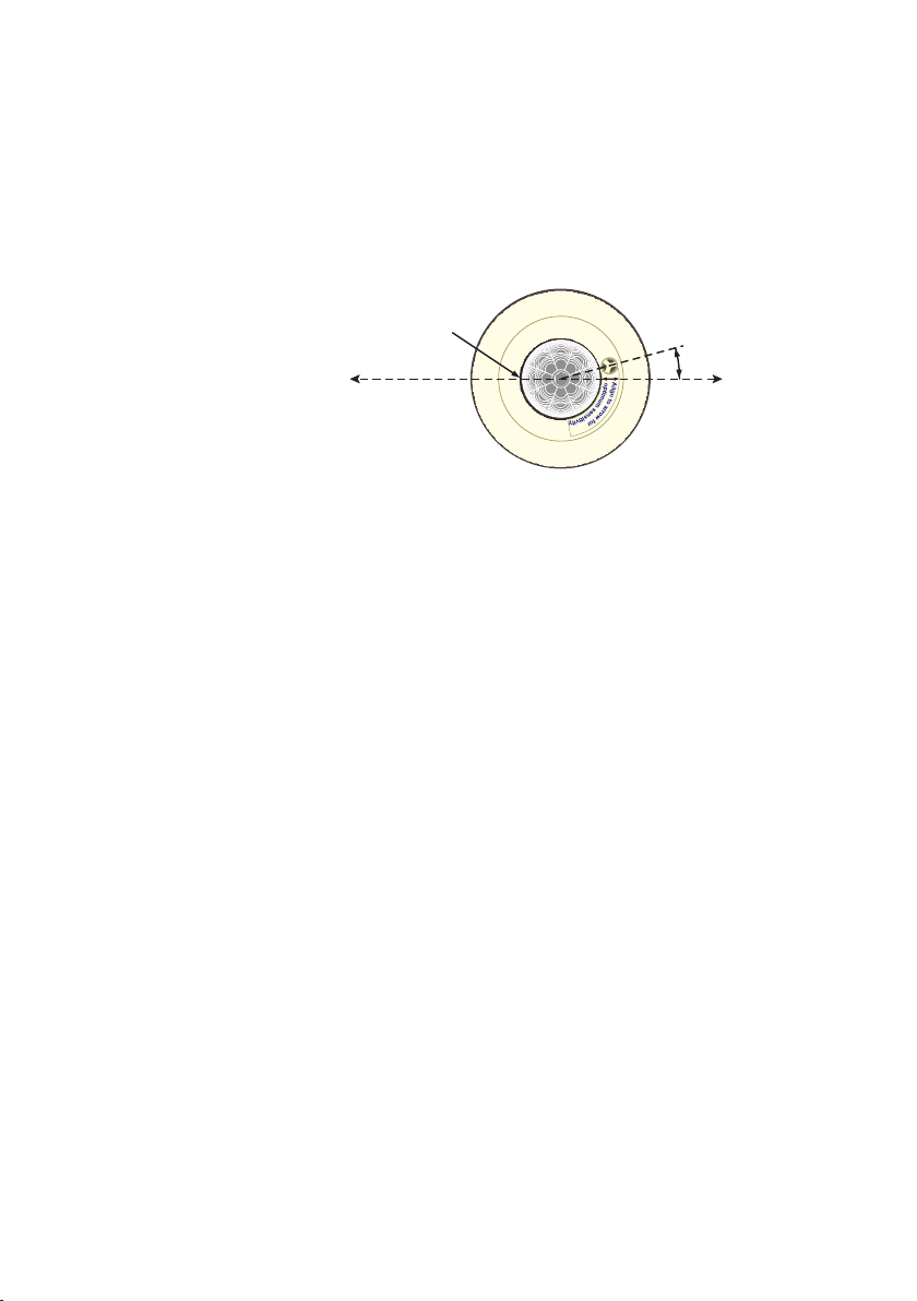
For aisle or corridor applications, there is
an optimum orientation for approach:
Centre
of facet
Path of optimum
sensitivity
Align to arrow
5
1 °
for optimum
sensitivity
Note: When operating in 'Regulating Photocell' mode, a closed feedback loop is formed by the luminaire, the reflective
surface beneath, and the photocell. For this control loop to function correctly, the photocell must have a good view of the
reflected light only from the luminaire(s) under its control – NOT from adjacent luminaires not under its control. This
means that the higher the detectors are mounted, the further apart they must be in order to ensure that they see mostly
'their own light'. Therefore, it is recommended that detectors are mounted on a pitch not less than 50% of the mounting
height when using the regulating photocell function.
Connection
Control of a group of luminaires is achieved via the detector’s two-wire digital control circuit. Each luminaire to be
controlled must contain a digital regulating type ballast with the appropriate DSI or DALI input. Ballast types must not be
mixed. Connect all ballasts in the control group (max 25) in parallel and also to the polarity-free digital output of the
detector.
Each luminaire is controlled completely by its digital input and therefore would normally have a permanent power supply.
If, however, it is desired to have manual wall switches, any or all of the fittings in a controlled group may also be controlled
in the traditional way - by turning off the power. The control circuit will continue to operate properly even if some of the
luminaires in the group have had mains power removed.
The MLS Bus must be connected to the MLS Bus Network. An MLS Bus Power Supply is required for each network of up
to 200 MLS devices. Refer to the MLS Bus Power Supply Installation Instructions before commencing any bus wiring.
It is imperative that the MLS Bus is wired in the correct type of cable. Normally this will be 1.5mm² unscreened twisted
pair. See Application Note AN4001 for details.
Do not connect mains to the MLS Bus wiring
‘OneSwitch’ Dimming
OneSwitch dimming affords local control to the end-user whereby a simple, momentary, push-to-make wallswitch can be
used to raise or lower the lighting level or to toggle the output ON/OFF. A short press of the switch (less than 1 second) will
toggle the output status while a longer press will raise or lower the output. Each time the switch is pressed, the direction of
dimming reverses. If the switch has not been pressed for 5 seconds, the direction will be up (brighter) - unless the output
is already above 90% in which case the direction is down. If the switch is held continuously, and the output reaches
maximum, the light output will remain at this level until the switch is released - a latching switch may be connected in
parallel allowing the occupancy detection to be overridden on (Note: If the initial direction was down, when the output
reaches minimum it will ramp back up automatically).
Setting the Regulating Photocell
This product is intended for use with high frequency regulating ballasts with digital control inputs. An infrared
programming tool, the HP2000, is required for programming the regulating light level set point.
Using the HP2000 Programmer, enter the Utilities menu and select ‘Set Light Level’. Use the ‘up’ and ‘down’ buttons to
manually adjust the light output from the luminaire(s) and when at the required level press and hold ‘OK’ to store. The
luminaire(s) will blink to acknowledge a successful store operation.
Page 3

Commissioning
Parame ter Options Pre-Set Notes
Power Up On / Off On
Sets the lum inaire state at pow er up irres pective of occupancy.
Use ful in reduci ng start-up load following power cut. Power-up off resp onds to occu pancy after 30 secon ds.
Res pons e Auto, Manual/Bus , Ma nual on ly Auto If set to Au to, the presen ce detector sw itches the lumi naire on and
off automatica lly. If s et to Ma nual Only, it can only be turned on by
usi ng OneSwitch or the ha nd-hel d controlle r. If set to Manual/Bus ,
an MLS Bus turn-on com mand for a Zone to which the detector
belon gs wi ll als o bring the light on. In all mo des the "When Vacant"
behaviour (be low) is i nitiated au tomatica lly.
Off Delay 1 min - 96 hrs, 10-s ec (walk-test), Disa bled 2 0 min s
The time for whi ch the lum inaire will s tay on following the last
detected m ovement. Also 10-s econd setting for wal k-testing .
On Sensi tivity 0-1 00 100
Sens itivity to m ovement whe n area is o ccupied. 100 = max
Bus Co nnect Yes / No Yes
Do/Do not Sign al/Recei ve on ML S Bus.
1st - 4th Zone Addre ss 1 -100; -- (no zone); Comm on 1-3 No Zone Individual Zone s influ encing and bein g influenced by this detector.
Corrido r 1 & 2 0-100; -- (no zone); Buildin g No Zone
Zone range s influ encing and bein g influenced by this detector.
Global 1 & 2 Rx Ye s / No No
Res pond to s elective load s hedding.
Manual Input Sha red / Local Local
Do/Do not s ignal OneSwitch com mands across the MLS Bus.
Start Lamps Max / Min Max
Sets the level at which the lamp s s trike when turni ng on.
Entry Scene 1-6 Scene 1
Sets whi ch scen e is recalled when uno ccupied area is entered.
Bright Out Yes / No N o If set to yes, movemen t fails to refres h the off delay if ambien t light
level exceeds 12 5% of set level and the lumi naire wi ll switch off
when the off dela y has elaps ed. NB: Dim mi ng mu st be s et to 100%.
Dim ming Reg 50%-R eg100 % 100% Can be s et to op erate betwee n 50% and 100% bal las t output from
max down to a bottom -end li mit whe n working on photocel l control.
Lam p Max 10%-10 0% 100%
Can be s et to li mit the abs olute maximu m outpu t of the ballas t in all
operatin g mod es.
Fade to Off Yes / No No
When no pres ence is detected , and after the off delay period, the
lam ps can fade out ins tead of switching off (approx 80 se conds to
fade from 10 0% to 0%).
When Vacant Off / Min / Reg <25% / Scene 6 Off Options for a va cant area after it has timed ou t. Luminai res can turn
off, remain at m inim um output, or regulate wi th a 25% output lim it,
until the next period of occup ancy. If program med to remain at
min imum, to regulate below 25% or go to sce ne 6, there are further
program mable op tions to switch off after 3 times the Off D elay (XTN )
or when no further moveme nt has be en detected an ywhere in the
build ing (BLD).
Set-point Low 0-1023 1023 Aiming po int as ph otocell ad jus ts ballas t output.
Set-point Hig h 0-1023 1023 L evel above which pho tocell s witches i ts output off (only if Bright
Out = Yes ).
100 Hou r Burn-In Burn-in 10 0 hrs / Cance l / Resum e 0 hr See Application Note: AN4028
Additional feature acc essible under Utilities on HP2000:
The factory default settings shown in the table below will be appropriate for most applications. However, the installer does have the
facility to re-programme all parameters using the HP2000 Programmer. These parameters may be re-programmed any number of
times and all settings will be retained in the event of a power loss.
Lens Mask
A lens mask (HBPIRLM) is available to mask end-of-aisle movement from being detected.
Important Additional Notes
1. All terminals on this product are provided for final connections. It is not intended that the product be used as a junction box
for looping cables.
2. A means for disconnection must be incorporated in the fixed wiring in accordance with the current wiring regulations.
3. Although nominally 12V, the dimming output is not SELV and therefore should be treated with the same respect as mains
with regard to wiring practice. The 0V line of the dimming output is almost at Neutral potential.
4. The dimming control output should be connected only to the control input of the ballasts - never to other detectors.
5. Due to the fact that the photocell is on the ceiling looking down, it is not possible for measurements made with a lux meter on
the working plane to remain constant when daylight illuminates the ceiling and the working plane to a differing extent.
Therefore, products of this type should be regarded as capable of maintaining an APPROXIMATE light level only.
Page 4

Dimensions Electrical Connections
OneSwitch
62mm
deep
100mm
Flange: 10mm deep
BALLAST
CONTROL
L
N
MLS Bus
Connection
230V 50Hz
Mains Supply
Polarity-free Digital Output
to compatible luminaires
To further
MLS Devices
Technical Data
MLS CABLE: 1.5mm unscreened twisted-pair : see Application Note AN4001
MAXIMUM RECOMMENDED MOUNTING HEIGHT: 16.0m
RANGE: 360 cone-shaped detection pattern, diameter (at floor level) = 1 x mounting height
2
o
h
d
MINIMUM MOUNTING PITCH (SPACING): 0.5 x mounting height (regulating mode only)
OPERATING VOLTAGE: 230V 50Hz (UK & Europe)
PRODUCT RATING & RECOMMENDED CIRCUIT PROTECTION: 10 Amps
CAPACITY: 25 ballasts
OUTPUT: 2-wire digital polarity free
PHOTOCELL: Regulating
OFF DELAY: Adjustable via Programmer - factory pre-set to 20 minutes
DEPTH REQUIRED BEHIND CEILING (FLUSH VERSION): 62mm from front flange plus an
allowance for the minimum bend radius of the cables.
WEIGHT: 200g approx
COLOUR: White
MATERIAL: Flame retardant PC/ABS
IP RATING: 4X
OPERATING TEMPERATURE: 0 C to 40 C
o o
Ex-Or
Novar ED&S Limited
Haydock Lane, Haydock, Merseyside WA11 9UJ
Tel: +44 (0)1942 719229
Fax: +44 (0)1942 508753
Email: technicalsales.ex-or@honeywell.com
www.ex-or.com
At the end of their useful life
the packaging and product
should be disposed of via a
suitable recycling centre.
Do not dispose of with normal
household waste.
Do not burn.
W4451F
 Loading...