

Connect - Lighting control modules and plug-in connection centres
MLS Connect Digital Remote Detectors
for CDW12U5, CDH4U5 & CDH8U5 LCMs
CDW12U5 Programmable Connection Centres and
CDH4U5/CDH8U5 Hard-Wired Intelligent Lighting Control
Modules support a range of dedicated high-performance
presence detectors. Detectors contain a photocell to
monitor total light levels, allowing the light output of
dimmable luminaires to be adjusted to suit the natural light
level available.
The range of detectors for remote mounting encompasses
both PIR and Microwave technology:
MLS2001CDR - 360 PIR presence detection
MLS2401CDR - 360 microwave presence detection
MLS2500CDR - directional microwave presence detection
All contain an infrared port that can be used both for local
control from a hand-held device when in service and for
initial commissioning of the CDW12U5/CDH4U5/CDH8U5
Intelligent LCM system.
Detectors connect to the LCM via RJ45 patch leads and all
are SELV devices when properly installed and connected.
Ready-made patch leads are available in lengths of 3m,
5m and 10m.
o
o
Commissioning
With the CDW12U5 and CDH4U5/CDH8U5 LCM systems,
all configuration information is held within the Connection
Centre itself, not the individual detectors. Most of the
parameters are set up with the aid of a dedicated
progamme running on a portable PC which communicates
with the LCM either by an infrared link, via one of the
attached detectors, or by a specialised serial link into the
LCM itself.
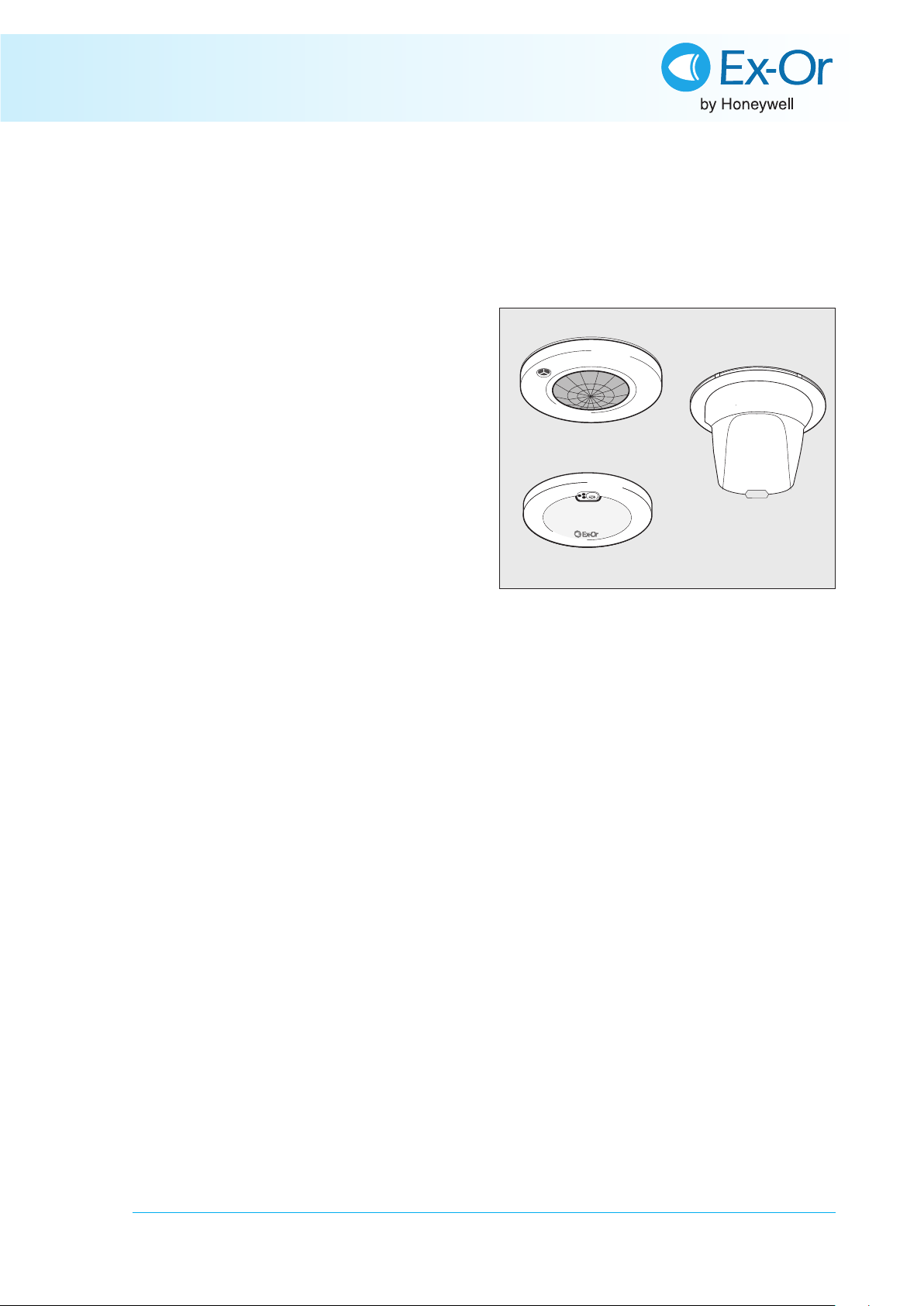
MLS2001CDR
MLS2401CDR
MLS2500CDR
Surface-mount versions
also available (suffix SM)
When setting the actual light levels around which dimming
or switching decisions are made, the system utilises the
same simple and convenient method as used for Ex-Or’s
traditional stand-alone detectors. An infrared programming
tool (HP2000 or HC5) is used to set the controlling or
switching set-point for the photocell. The setting is then
transmitted from the detector to the LCM where it is
uniquely associated with that particular detector. The
setting will be preserved in the event of power failure. All
settings can be re-programmed any number of times.
(See ‘Setting the Regulating Photocell’ and ‘Setting the
Switching Photocell’ sections of installation instructions for
details of setting procedure.)
Please check www.ex-or.com to ensure this is the most
recent issue - Ref: D4123B
Ex-Or, Haydock Lane, Haydock, Merseyside WA11 9UJ
T: +44 (0)1942 719229 F: +44 (0)1942 272767 E: technicalsales.ex-or@honeywell.com & orders.ex-or@honeywell.com www.ex-or.com
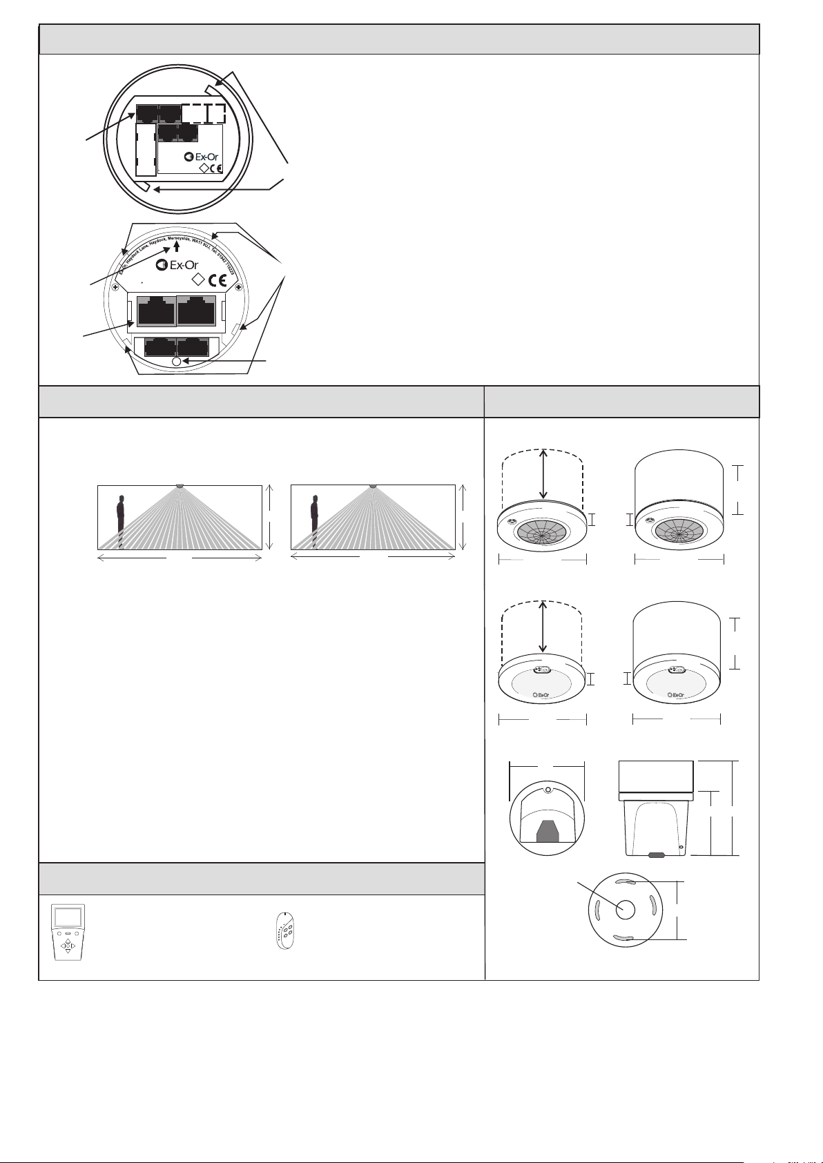
Positioning, Fixing & Connections
View on back of
MLS2001CDR
MLS2401CDR
Detectors
Socket for
Patch Lead to
LCM
To CD
Box
Ex-Or
Haydock Lane
Haydock
Merseyside
WA11 9UJ
Do Not
Connect
Tel: 01942 719229
Fax: 01942 272767
II
II I
Bayonet Fixing
Do Not
Lugs
Connect
Positioning Notes
Do not mount within 0.25m of a luminaire.
The MLS2401CDR should not be positioned on a pitch narrower than 5m.
Microwave detectors (MLS2401CDR & MLS2500CDR) are extremely sensitive to movement and
must be installed on a rigid surface that will not itself be subject to movement. Microwaves can
penetrate lightly built partitions, glass etc and thus movement in adjacent spaces can cause
spurious triggering if the orientation and sensitivity settings of the detector are not carefully
managed. They are not recommended for areas where there are large areas of metal such as
metal ceiling panels as unpredictable sensitivity may result.
Fixing (Outline guidance - see installation instructions for full details)
MLS2001CDR & MLS2401CDR
View on Back of
MLS2500CDR
Detector
Arrow Symbol
MLS2500CDR
Power consumption <10W
ta 0..40 C
DO NOT OPEN
I
II I
I
No Serviceable Parts Inside.
Bayonet Tab
Receptacles
Flush Versions - Depth required behind ceiling: 62mm from front flange plus an allowance for the
minimum bend radius of the cable. Sinking box fits into a 89mm diameter hole in ceiling tile or
plasterboard ceiling. To avoid damage to ceiling tile, do not overtighten. No access above the
ceiling is necessary. The unit fits into the housing with a simple bayonet action.
Surface Versions - The housing may be secured to a hard surface or a BESA box. The unit fits into
the housing with a simple bayonet action.
MLS2500CDR
Semi-flush Version - Use a hole saw to drill a 76mm hole into the ceiling tile. The flush ring is
Socket for
Patch Lead to
LCM
To CD
Box
Do Not
Connect
Locking
Screw
designed to clamp the tile between its two halves.
Surface Version - The back-box can be secured directly to a hard surface or to a conduit stop
end box.
Technical Data
MLS2001CDR & MLS2401CDR
MAX RECOMMENDED MOUNTING HEIGHT: 3.0m
RANGE: Cone-shaped detection pattern. Diameter (at floor level) =
2.4 x mounting height (MLS2001CDR) 2.8 x mounting height (MLS2401CDR)
MLS2001CDR MLS2401CDR
2.5m
2.5m
Dimensions
MLS2001CDR
62mm deep
behind ceiling
Flange:
10mm
deep
MLS2001CDRSM
62mm
deep
6.0m
7.0m
OPERATING VOLTAGE: 12V DC, SELV if installed correctly
PHOTOCELL: Regulating
DEPTH REQUIRED BEHIND CEILING (FLUSH VERSIONS):
62mm plus an allowance for the minimum bend radius of the patch lead
WEIGHT: 170g approx - MLS2001CDR
200g approx - MLS2401CDR
COLOUR: White
MATERIAL: Flame retardant PC/ABS
IP RATING: 3X - MLS2001CDR
2X - MLS2401CDR
MLS2500CDR
MAX RECOMMENDED MOUNTING HEIGHT: 3.5m
RANGE: Adjustable up to 20m
OPERATING VOLTAGE: 12V DC, SELV if installed correctly
PHOTOCELL Regulating
DEPTH REQUIRED BEHIND CEILING (SEMI-FLUSH VERSION):
40mm plus an allowance for the minimum bend radius of the patch lead
WEIGHT: 130g approx
COLOUR: White
MATERIAL: Flame retardant PC/ABS
IP RATING: 4X
Accessories
HP2000 MLS Digital Programmer
Menu-driven LCD Programmer with
automatic equipment recognition and
parameter download facilities.
HC5 Universal Hand-held Controller
Allows manual override.
100mm
MLS2401CDR
62mm deep
behind ceiling
100mm
74
20mm
back
entry
Rear View
Flange:
15mm
deep
MLS2500CDR
100mm
MLS2401CDRSM
100mm
50.8
60
62mm
deep
95
Ex-Or operates a genuine policy of continuous improvement. You may expect the specification to be regularly enhanced. For latest technical information, please visit www.ex-or.com.
Part Numbers
MLS2001CDR 360 PIR Detector - flush
MLS2001CDRSM 360 PIR Detector - surface
MLS2401CDR 360 Microwave Detector - flush
MLS2401CDRSM 360 Microwave Detector - surface
o
o
o
o
MLS2500CDR Directional Microwave Detector - semi-flush
BT5E030GY 3m Detector Patch Lead
BT5E050GY 5m Detector Patch Lead
BT5E100GY 10m Detector Patch Lead
HP2000 MLS Digital Programmer
HC5 Universal Hand-held Controller c/w wall bracket
MLS2500CDRSM Directional Microwave Detector - surface
Ref: D4123B
 Loading...