

Page 1
ML4125, ML4135, ML8125, ML8135
Fast-Acting, Two-Position Actuators
FOR HEATING, VENTILATION AND
AIR-CONDITIONING APPLICATIONS
PRODUCT DATA
FEATURES
• Integral spring return.
• -40 to 130°F (-40 to 54°C) operating temperature range.
• No audible noise during holding.
• Electronic circuitry provides efficient operation while
eliminating the need for limit switches.
• Ninety-five degree angle of rotation.
• Die-cast aluminum housing.
• Housing design allows flush mounting to damper.
• Integral junction box with three conduit openings
eliminates need for separate wiring box.
• Direct mounting to 3/8 or 1/2 in. round or square shaft.
APPLICATION
The ML4125, ML4135, ML8125 and ML8135 Fast-Acting,
Two-Position Actuators are spri ng return direct coupled
actuators (DCA) with an integral junction box for on/off
damper control. The actuator accepts an on/off signal from
a single-pole, single-throw (spst) controller. Models are
available with clockwis e (cw) or counterclockwise (ccw)
spring return and are designed for heating, ventilation, and
air-conditioning (HVAC) applications.
IMPORTANT
This actuator is not to be used in fire/smoke
applications requiring UL555/555S approval.
ML4125, ML8125
• 100 lb-in. (11.3 N•m) minimum driving torque.
• 25 to 40 second drive timing (load dependant).
• Models available for 24, 120, and 230 Vac.
ML4135, ML8135
• 40 lb-in. (4.5 N•m) minimum driving torque.
• 20 to 25 second drive timing (load dependant).
• Models available for 24 and 120 Vac.
APPLICABLE LITERATURE
— Motor/Actuator Selection Guide
for Damper Applications 63-8419
— Engineering Manual of Automatic Control
(also called The Gray Manual) 77-1100
— Direct Coupled Actuator
Quick Selection Guide 63-8553
— Damper Torque Calculator 63-8437
Contents
Application ........................................................................ 1
Features ........................................................................... 1
Specifications ................................................................... 2
Ordering Information ........................................................ 2
Installation ........................................................................ 4
Operation .......................................................................... 6
Checkout .......................................................................... 6
® U.S. Registered Trademark
Copyright © 2000 Honeywell • All Rights Reserved
N314
63- 2567-3
Page 2

ML4125, ML4135, ML8125, ML8135 FAST-ACTING, TWO-POSITION ACTUATORS
SPECIFICATIONS
Models:
ML4125A ccw 120 100 (11.3)
ML4125B cw
ML4135A ccw 40 (4.5)
ML4135B cw
ML4125C ccw 230 100 (11.3)
ML4125D cw
ML8125A ccw 24
ML8125B cw
ML8135A ccw 40 (4.5)
ML8135B cw
Dimensions:
Electrical Ratings:
Power Input:
Power Consumption (at Nominal Voltage):
Temperature Ratings:
Ambient: -40°F to 130°F (-40°C to 55°C).
Shipping and Storage: -40°F to 140°F (-40°C to 60°C).
Humidity Ratings:
See Table 1.
Table 1. ML4125/4135, ML8125/8135 DCA Models.
Model
ML4125A,B: 120 Vac +10%, -15%, 60 Hz.
ML4125C,D: 230 Vac ±10%, 50 Hz.
ML4135: 120 Vac ±10%, 60 Hz.
ML8125, ML8135: 24 Vac +20%, -10%, 50/60 Hz.
ML4125A,B: Running: 0.16A, 15W.
ML4125C,D: Running: 0.12A, 18.6W.
ML4135: Running: 0.18A, 18W.
ML8125: Running: 15.6 VA.
ML8135: Running: 18 VA.
Spring Return
Direction
See Fig. 1.
Holding: 0.10A, 5W.
Holding: 0.10A, 7W.
Holding: 0.11A, 9W.
Holding: 4 VA.
Holding: 8.5 VA.
5% to 95% RH noncondensing.
Voltage
in Vac
Torque
in lb-in. (N•m)
Electrical Connections:
ML4125A,B, ML4135, ML8125, ML8135: Two color coded
16 in. leads; includes ground screw.
ML4125C,D: 1m appliance cable.
Three 7/8 in. holes for conduit connections (fittings not
included).
Controller Type:
ML4125A,B, ML4135: Line voltage (120 Vac), two-position,
spst (Series 40).
ML4125C,D: Line voltage (230 Vac), two-position, spst
(Series 40).
ML8125, ML8135: Low voltage (24 Vac), two-position, spst
(Series 80).
Device Weight:
Stroke:
To rque Rating s:
Driving:
Spring Return:
Holding (minimum): 100 lb-in. (11.3 N•m).
Stall Maximum:
Noise Rating (Maximum):
Driving/Spring Return: 65 dBA at 1m.
Holding: 20 dBA at 1m (no audible noise).
95° ± 3°, mechanically limited.
Minimum:
ML4125, ML8125: 100 lb-in. (11.3 N•m).
ML4135, ML8135: 40 lb-in. (4.5 N•m).
Typical:
ML4125, ML8125: 170 lb-in. (19.2 N•m).
ML4135, ML8135: 100 lb-in. (11.3 N•m).
Minimum:
ML4125, ML8125: 80 lb-in. (9 N•m).
ML4135, ML8135: 40 lb-in. (4.5 N•m).
Typical:
ML4125, ML8125: 100 lb-in. (11.3 N•m).
ML4135, ML8135: 50 lb-in. (5.7 N•m).
Derated (from -40°F to 0°F [-40°C to -18°C]):
ML4135, ML8135: 30 lb-in. (3.4 N•m).
ML4125, ML8125: 240 lb-in. (27.1 N•m).
ML4135, ML8135: 150 lb-in. (17 N•m).
5 lb (2.3 kg).
ORDERING INFORMATION
When purchasing replacement and modernization products from your TRADELINE® wholesaler or distributor, refer to the
TRADELINE® Catalog or price sheets for complete ordering number.
If you have additional questions, need further information, or would like to comment on our products or services, please write or
phone:
1.
Your local Home and Building Control Sales Office (check white pages of your phone directory).
2.
Home and Building Control Customer Logistics
Honeywell, 1885 Douglas Drive North
Minneapolis, Minnesota 55422-4386 (612) 951-1000
In Canada—Honeywell Limited/Honeywell Limitée, 155 Gordon Baker Road, North York, Ontario M2H 3N7.
International Sales and Service Offices in all principal cities of the world. Manufacturing in Australia, Canada, Finland, France,
Germany, Japan, Mexico, Netherlands, Spain, Taiwan, United Kingdom, U.S.A.
63-2567—32
Page 3
ML4125, ML4135, ML8125, ML8135 FAST-ACTING, TWO-POSITION ACTUATORS
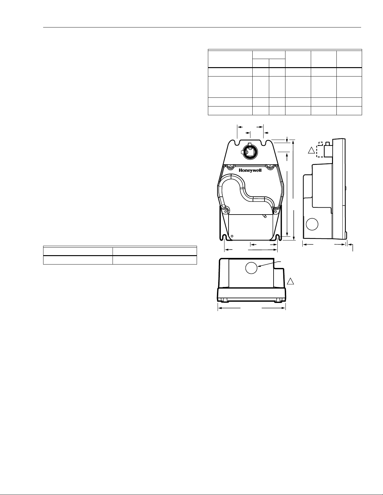
2 (51)
1 (25)
5/8
(17)
6 3/8
(161)
7 1/2
(192)
4 (102)
7/8 (22)
5 1/8 (129)
2 (51) 3 5/16 (84)
1/16 (2)
M17538
ML4135/ML8135 HAVE SHORTER
HUB WITH TWO SET SCREWS.
ML4125/ML8125 HAVE LONGER
HUB WITH FOUR SET SCREWS.
1
1
Mounting:
3/8 in. (10 mm) to 1/2 in. (13 mm) square or round damper
shafts. Actuator ca n b e m ounted with shaft in any pos iti on.
Secure hub to shaft with:
ML8125, ML4125A,B: Four 1/4-28 UNF set screws. Use
1/8 in. Allen wrench to tighten set screws.
ML8135, ML4135: Two 1/4-28 UNF set screws. Use 1/8 in.
Allen wrench to tighten set screws.
ML4125C,D: Four 3 mm set screws. Use 3 mm Allen wrench
to tighten set screws.
IMPORTANT
Honeywell does not recommend using linkages with
these actuators because side-loading of the output
hub reduces actuator life.
Minimum Damper Shaft Length:
1-3/4 in. (45 mm).
Timing:
Drive Open:
ML4125, ML8125: 25 to 40 seconds (load dependant).
ML4135, ML8135: 20 to 25 seconds (load dependant).
Spring Close:
ML4125, ML8125: 20 to 25 seconds.
ML4135, ML8135: 15 seconds.
Design Life (at Rated Voltage):
ML4125, ML8125: 80,000 full-stroke cycles.
ML4135, ML8135: 60,000 full-stroke cycles.
T a ble 3. App rovals.
ML4125
ML4135 ML8125 ML8135A,B C,D
UL/cUL X X X X X
UL873
XXX X X
Plenum Rating,
File No. E4436
CE X X X
C-TICK X X
Environmental Protection Ratings:
See Table 2.
Table 2. Environmental Ratings.
All Devices ML4125C,D, ML8125, ML8135
NEMA1 IP54
Approvals:
See Table 3.
Accessories:
201391 Shaft Adapter for 3/8 in. (10 mm) shafts.
205649 Mounting Bracket (included with the actuator).
32003532-001 Adjustable Switch Package, two 10A
externally-mount ed full y-a dj ust abl e sw itc he s.
Fig. 1. ML4125/4135, ML8125/8135
dimensiona drawing in in. (mm).
3 63-2567—3
Page 4

ML4125, ML4135, ML8125, ML8135 FAST-ACTING, TWO-POSITION ACTUATORS
INSTALLATION
When Installing this Product...
1.
Read these instructio ns c aref ull y. Failure to foll ow them
could damage the product or cause a hazardous
condition.
2.
Check the ratings given in the instructions and on the
product to make sure the product is suitable for your
application.
3.
Installer must be a trained, experienced service
technician.
4.
After installation is complete, check out product
operation as provided in these instructions.
IMPORTANT
All wiring must agree with applicable codes,
ordinances and regulations.
WARNING
Electrical Power Hazard.
Line voltage can cause death or serious injury
and short equipment circuitry.
Disconnect power supply before installation.
1
CAUTION
Electrical Shock or Equipment Damage Hazard.
Low voltage can shock individuals or short
equipment circuitry.
Disconnect power supply before installation.
Location and Mounting
CAUTION
Equipment Damage Hazard.
Tightly securing actuator to damper housing can
damage actuator.
Mount actuator t o all ow i t t o f loa t along its vertical ax is.
The actuators are designed to open a damper by driving the
damper shaft in either clockwise or counterclockwise
direction. The actuator housing has two slots on the
bottom that, with a 205649 Mounting Bracket, secure it flush
to a damper box (see Fig. 2). When mounted correctly, these
slots allow the actuato r to
damper shaft.
NOTE: ML4125, ML4135, ML8125 and ML8135 Actuators
are shipped in the fully closed position.
float
without rotating relative to the
ENSURE THAT MOUNTING ASSEMBLY PREVENTS ACTUATOR
1
ROTATION AND ALLOWS ACTUATOR TO FLOAT ALONG INDICATED
AXIS. WHEN TOO TIGHT, THE RESULTING BINDING CAN DAMAGE
THE ACTUATOR OR REDUCE TORQUE OUTPUT.
Fig. 2. Mounting actuator to damper housing.
NOTE: The actuator mounts flush with the damper box.
M17519
Preparation
Before mounting the actuator onto the damper shaft, determine
the damper shaft size (3/8 in. to 1/2 in. [10 mm to 13 mm]).
If damper shaft is 3/8 in. (10 mm) round or square, use part
number 201391 Shaft Adapter. Place adapter opposite
set screws (see Fig. 3).
NOTE: The damper shaft adapter centers a 3/8 in. (10 mm)
damper shaft in the hub. Failure to use adapter can
cause mounting screws to loosen. A 1/2 in. (13 mm)
damper shaft does not require an adapte r.
SHAFT ADAPTER
Fig. 3. Using damper shaft adapter for
3/8 in. (10 mm) damper shafts.
63-2567—34
M2064
Page 5

ML4125, ML4135, ML8125, ML8135 FAST-ACTING, TWO-POSITION ACTUATORS
L1
24 VAC
L2
RED
BLACK
R
W
M17585
( )
( )
L1
120
VAC
L2
WHITE
BLACK
R
W
M17589
( )
( )
L1
230
VAC
L2
BLUE
BROWN
R
W
M17588
( )
( )
Installation
CAUTION
Device Malfunction Hazard.
Improper set screw tightening causes device
malfunction.
Tighten set screws with proper torque to prevent
damper shaft slippage.
CAUTION
Actuator Damage Hazard.
Using actuator as shaft bearing causes device
damage.
Use actuator only to supply rotational torque. Avoid
any side loads to actuator output coupling bearings.
To install actuator, proceed as follows:
1.
Place actuator over damper shaft; and hold mounting
bracket in place. See Fig. 2.
2.
Mark screw holes on damper housing.
3.
Remove actuator and mounting bracket.
4.
Drill or center-punch holes for mounting screws (or use
no.10 self-tapping sheet metal screws).
5.
Turn damp er b lad es to d esired normal (closed) position.
6.
Place actuator and mounting bracket back into position
and secure bracket to damper box with sheet metal
screws.
7.
Tighten set screws securely into damper shaft using
minimum 30 lb-in., maximum 60 lb-in. torque. Use
1/8 in. or 3 mm Allen wrench (see Specifications for
details) to tighten set screws.
Wiring
IMPORTANT
1. All wiring must comply with local electrical codes,
ordinances and regulations.
2. Voltage and frequency of transformer used with
ML8125 or ML8135 must correspond with the
characteristics of power supply and actuator.
3. Use wires rated for at least 75°C (167°F).
See Fig. 4 through 6 for typical wiring diagrams.
Fig. 4. Typical 24 Vac wiring.
Fig. 5. Typical 120 Vac wiring.
WARNING
Electrical Power Hazard.
Line voltage can cause death or serious injury
and short equipment circuitry.
Disconnect power supply before installation.
CAUTION
Electrical Shock or Equipment Damage Hazard.
Low voltage can shock individuals or short
equipment circuitry.
Disconnect power supply before installation.
BROWN
BLUE
BLACK
WHITE
RED
5 63-2567—3
Fig. 6. Typical 230 Vac wiring.
Table 4. Color Translations.
GFIE
BRAUN BRUN BRUNO CAFE
BLAU BLEU AZZURRO AZUL
SCHWARZ NOIR NERO NEGRO
WEISS BLANC BIANCO BLANCO
ROT ROUGE ROSSO ROJO
Page 6

ML4125, ML4135, ML8125, ML8135 FAST-ACTING, TWO-POSITION ACTUATORS
OPERATION
The actuators are operated by an s ps t tw o-po si tio n co ntrol le r.
When using an spst tw o-position c ontroller , the ac tuator drives
to the damper fully open position when controller contact
makes and spring returns to the damper fully closed po sition
when controller contac t bre ak s. Th e ac tuat or dro ps to hol din g
power level on detection of stall, indepe nd ent of hub pos iti on.
If power fails, the actuator spring returns to the 0° pos iti on.
CHECKOUT
ML4125A,B, ML4135 (120 Vac model)
1.
Check damper position.
2.
Connect 120 Vac to the black and white leadwires to
drive the damper to the open position. The actuat or
should drive the damper.
3.
If the actuator does not run, remove power for at least
two seconds.
4.
If the actuator spring returns, allow it to close entirely,
then return to step 2.
5.
If the actuator does not spring return, verify that the
actuator is properly installed. See Installation section.
6. I
f the actuator is correctly installed but neither runs nor
spring returns, replace the actuator.
ML4125C,D (230 Vac model)
1.
Check damper position.
2.
Connect 230 Vac to the blue and brown leadwires to
drive the damper to the open position. The actuat or
should drive the damper.
3.
If the actuator does not run, remove power for at least
two seconds.
4.
If the actuator spring returns, allow it to close entirely,
then return to step 2.
5.
If the actuator does not spring return, verify that the
actuator is properly installed. See Installation section.
6. I
f the actuator is correctly installed but neither runs nor
spring returns, replace the actuator.
ML8125, ML8135 (24 Vac model)
1.
Check damper position.
2.
Connect 24 Vac to the red and black leadwires to drive
the damper to the open position. The actuator should
drive the damper.
3.
If the actuator does not run, remove power for at least
two seconds.
4.
If the actuator spring returns, allow it to close entirely,
then return to step 2.
5.
If the actuator does not spring return, verify that the
actuator is properly installed. See Installation section.
6.
If the actuator is correctly installed but neither runs nor
spring returns, replace the actuator.
63-2567—36
Page 7

D Montageanweisung
M11882
a
b
c
HEX
4mm
MIN: 45 lb-in. (5.1 Nm)
MAX: 60lb-in. (6.8 Nm)
F Instru ctions d’Installation
I Istruzioni per I’Installazione
NL Installatievoorschrift
DK Installasjonsinstruks
N Installationsinstrukioner
SF Asennusohje
S Installations Instrukioner
E Instrucciones de montaje
ML4125, ML4135, ML8125, ML8135 FAST-ACTING, TWO-POSITION ACTUATORS
M11875
A2
a
c
M11876
A6
AA1, A4
24 VAC
!
230 VAC
ASSEMBLY
EINBAU
D
MONTAGE
F
MONTAGGIO
I
NL
DK
N
FIN
S
E
A3
MONTAGE
MONTERE
MONTERING
ASENTAMINEN
MONTERA
MONTAJE
M11874
M11876
A5
a
b
d
b
a
b
M12030
b
M11881
7 63-2567—3
a
Page 8

Printed in U.S.A. on recycled
paper containing at least 10%
post-consumer paper fibers.
ML4125, ML4135, ML8125, ML8135 FAST-ACTING, TWO-POSITION ACTUATORS
M11886
BB1B2
24 VAC
!
230 VAC
a
DISASSEMBLY
AUSBAU
D
DÉMONTAGE
F
SMONTAGGIO
I
DEMONTAGE
NL
AFMONTERE
DK
DEMONTERE
N
PURKAMINEN
FIN
NEDMONTERA
S
DESMONTAJE
E
M11884
M11887
M11888
a
b
b
HEX
4mm
B4B3
M11885
Home and Building Control Home and Building Control Honeywell Asia Pacific Inc. Honeywell Europe S.A. Honeywell Latin American
Honeywell Honeywell Limited-Honeywell Limitée Room 3213-3225 3 Avenue du Bourget
1985 Douglas Drive North 35 Dynamic Drive Sun Hung Kai Centre 1140 Brussels 480 Sawgrass Corporate Parkway
Golden Valley, MN 55422 Scarborough, Ontario No. 30 Harbour Road Belgium Suite 200
63-2567—3 B.B. Rev. 7-00 www.honeywell.com
M1V 4Z9 Wanchai Sunrise FL 33325
Hong Kong
Region
 Loading...