

Page 1
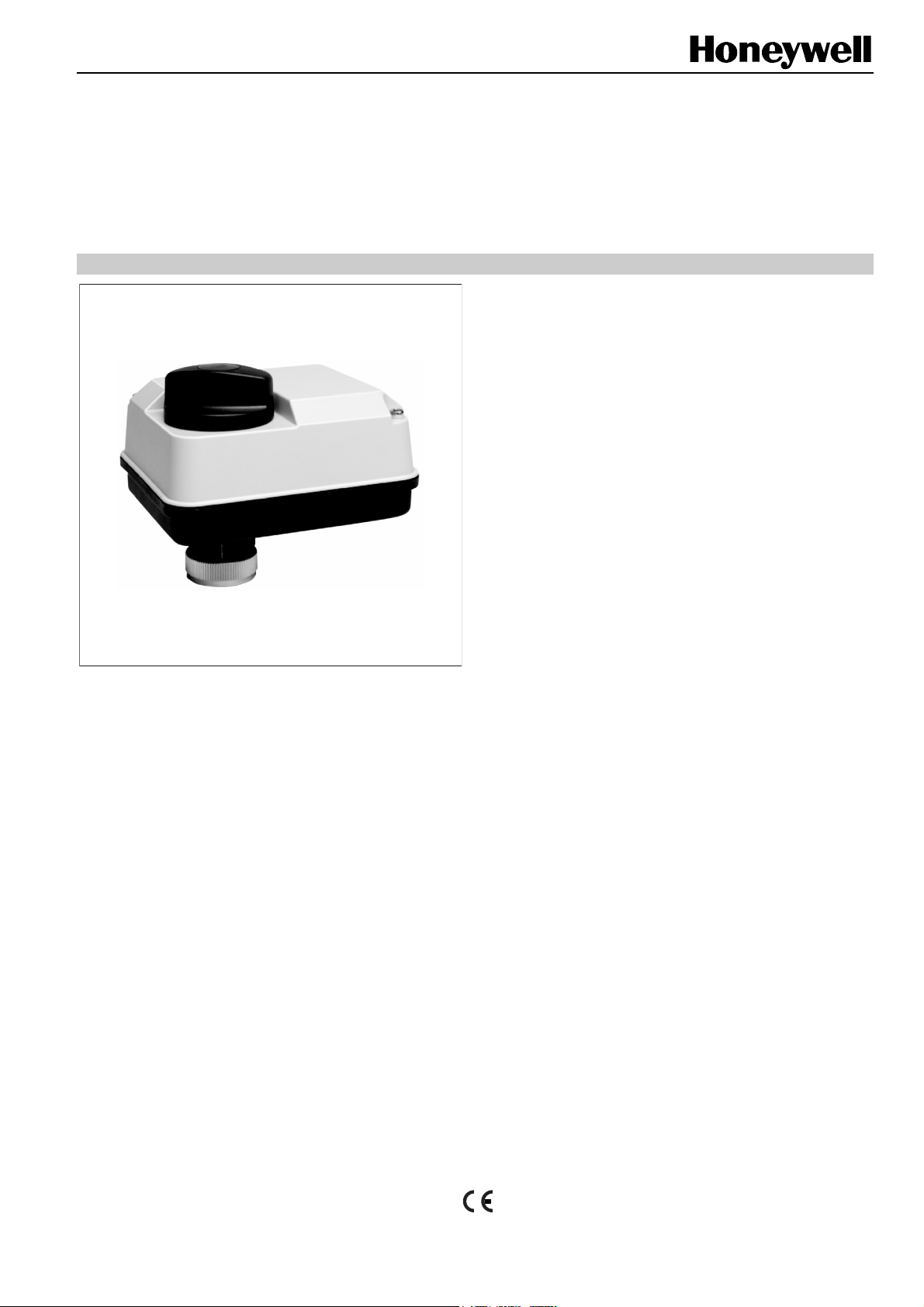
ML7430E/ML7435E
ELECTRIC LINEAR ACTUATORS
FOR MODULATING CONTROL
SPECIFICATION DATA
FEATURES
• 0...10 Vdc / 2...10 Vdc signal input
• Fast run-time
• Low power consumption
• Quick and easy installation
• No separate linkage required
• No calibration
• Force-limiting end switches
• Spring return (ML7435E)
• Manual operator
• Synchronous motor
• Direct / reverse action adjustable
• Maintenance-free
GENERAL
The ML7430E and ML7435E Electric Linear Actuators are
designed to provide modulating control in closed control loops
together with the small linear valves V5832B/V5833A
(DN25...DN40) and V5825B/V5872B for high-differential
pressure.
These valve-actuator combinations are suitable especially for
integration into compact or conventional stations for direct or
indirect district heating connections, air handling units and
roof top units for zone control, and domestic hot water
applications.
The actuators are microprocessor-controlled for exact
positioning. The direction of movement is reversible. The
V5825B or V5872B valve and ML7435E actuator combination
provides safe close-off function and is approved according to
DIN EN 14597.
SPECIFICATIONS
Temperature Limits
Ambient operating limits 0...+50 °C at 5 to 95% rh
Ambient storage limits -40...+70 °C at 5 to 95% rh
Medium valve temperature max. +130 °C
Signals
Input voltage range Y = 0...10 Vdc or 2...10 Vdc
Input resistor R
Signal source output register Max. 1 kΩ
Safety
Protection standard IP54 as per EN60529
Protection class II as per EN60730-1
Flame retardant V0 as per UL94 (optional
with metal cable gland)
Software class A as per EN 60730-1
Operating mode See Table 1 on pg. 2
Wiring
Terminals 1.5 mm
Cable entry M20x1.5
Weight 0.37 kg / 0.5 kg
Dimensions See Fig. 2 and Fig. 3
Material
Cover ABS-FR
Base Glass fiber reinforced plastic
= 100 kΩ
i
2
® U.S Registered Trademark
Copyright © 2009 Honeywell Inc. • All Rights Reserved EN0B-0260GE51 R0209
Page 2
ML7430E/ML7435E Electric Linear Valve Actuator
Table 1. Specifications, by model
OS-number ML7430E1005 ML7435E1004
supply voltage
power consumption
signal input 0(2) Vdc (factory setting)
signal input 10 Vdc (factory setting)
nominal stroke
run-time at 50 Hz
nominal stem force
spring return time (6.5 mm stroke)
spring return direction
operating mode (as per EN 60730-1, 6.4)
OPERATION
General
The drive of a synchronous motor is converted into linear
motion of the actuator stem by using a spur gear transmission. Actuator and valve are directly connected by a nut.
An integrated mechanism limits the stem force. Installed
microswitches switch off the actuator precisely when the
specified stem force is reached.
The close-off position is self-adjusting by means of an automatic synchronization function. Synchronization is performed
when the applied control signal is 0 V or 10 V. The actuator
then checks its end position every 20 minutes. Any manual
operation will be detected within 20 minutes, at the latest, and
the actuator will return to its end position after that control
cycle.
4 VA 4 VA
15 s 60 s
type 1B type 2B
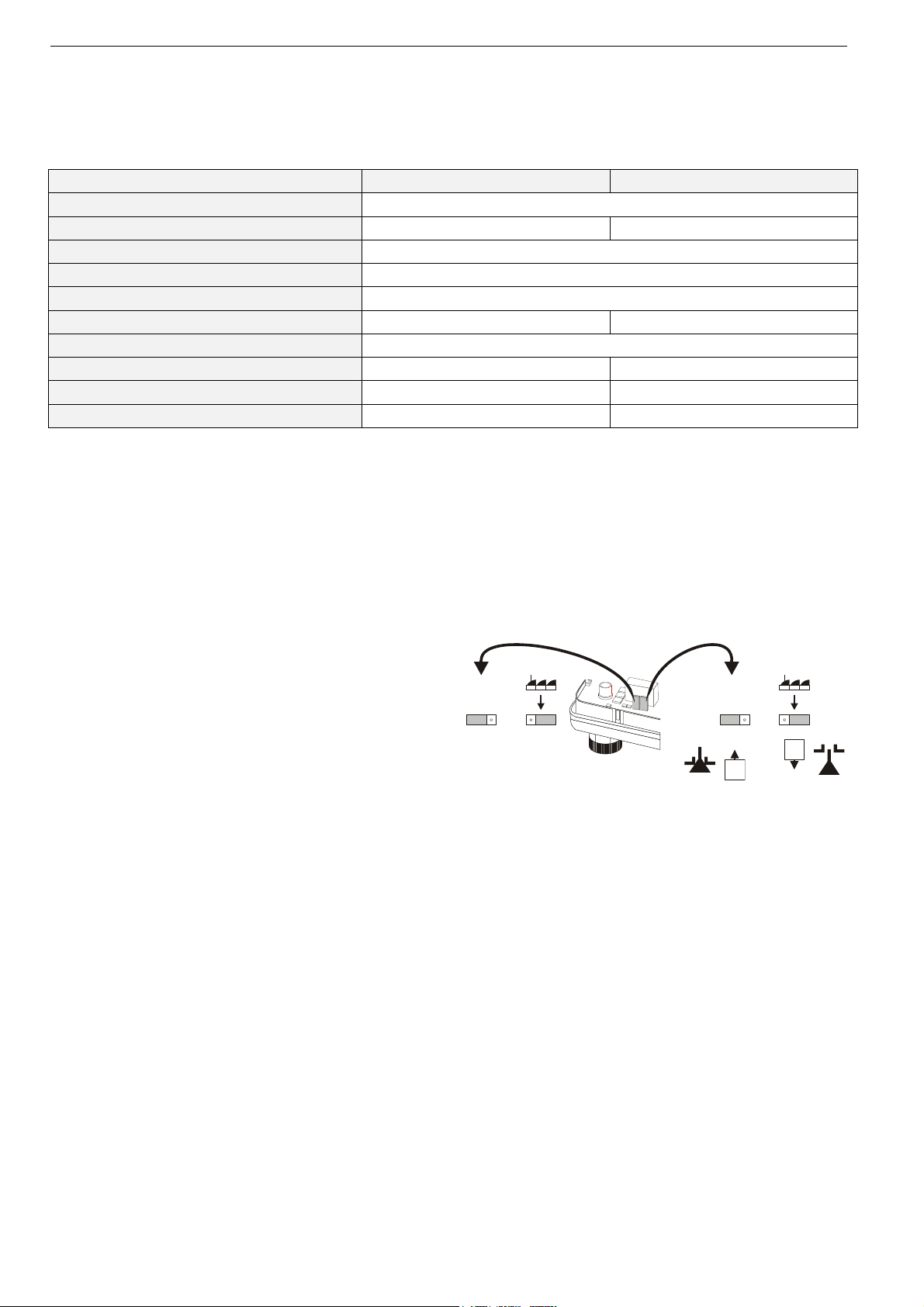
Input Signal Range
The range of the analog input signal Y (0...10 Vdc or
2...10 Vdc) can be selected by changing the position of
jumper plug W2 (see Fig. 1). The factory set is at 0...10 Vdc.
Direction of Action
The direction of action (direct or reverse) can be selected by
changing the position of jumper plug W1 (see Fig. 1). It is set
by the factory such that the stem extends at increasing signal
and retracts at decreasing signal (direct action).
W2
24 Vac -15/+20%, 50/60 Hz
actuator stem retracts
actuator stem extends
6.5 mm
400 N
-- max. 20 s
-- actuator stem retracts at power failure
W1
0...10 V2...10 V
10 V
Manual Operation for ML7430E
The actuators are equipped with a manual operator. Manual
operation is possible only after the power supply has been
switched off or disconnected. It should be used only to check
the valve operation. To operate, turn the manual operator
knob clockwise to move the stem downward and counterclockwise to move the stem upward.
NOTE: Jumper plugs W1 and W2 are accessible after the
Fig. 1. Jumper plugs W1 and W2
cover has been removed (see Fig. 1).
Manual Operation for ML7435E
The actuators are equipped with a manual operator (for 8 mm
Hex Key). Manual operation is possible only after the power
supply has been switched off or disconnected. It disables the
actuators safety function and should be used only to check
the valve operation. The manual operator is located under the
cover.
Electrical Installation
To avoid the voltage drop influence of the cabling, it is
recommended that you wire control signal Y and 24 V⊥
separately from power supply wiring.
10 V
EN0B-0260GE51 R0209 2
Page 3

ML7430E/ML7435E ELECTRIC LINEAR ACTUATORS
Y-Signal Override
To override the Y-signal and force the actuator in 0% or
100% stroke position, inputs 1 and 2 (see Fig. 4) must be
connected as follows:
• 0% stroke position (stem fully retracted):
24 V⊥ applied to input Y
• 100% stroke position (stem fully extended):
24 V
∼ applied to input Y
• or vice versa if reverse action is selected
Y-Signal break
In the event of a wire break at the Y-signal input, the
actuator is moved into the 0 V signal position (safety
position).
Spring Return (ML7435E1004, only)
The ML7435E1004 spring return actuator provides a
defined safety position of the valve in case of power failure.
DIMENSIONS
126 108
In the event of a power failure, the actuator retracts its
stem.
Suitable Valves
DN15 DN20 DN25 DN32 DN40 order no.
close-
off pres-
sure in
kPa
1600 -- 1600 -- -- V5872B
-
-
2500 2500 2500 2500 -- V5825B
-- 1600 1200 1000 V5832B
-- 1600 1200 1000 V5833A
Approvals
NOTE: Actuator ML7435E1004 in combination with the
following valves is approved according to DIN EN
14597:
valve OS-no. DIN registration no.
V5825B 1F152/08
97
33 33
Fig. 2. ML7430E (dimensions in mm)
126 108
81
33 33
Fig. 3. ML7435E (dimensions in mm)
3
EN0B-0260GE51 R0209
Page 4

WIRING
ML7430E/ML7435E ELECTRIC LINEAR ACTUATORS
0(2)...10 Vdc
W2
M
W1
10 V 10 V
0(2)...10 Vdc
Y
3
Y
0%
2
24 V 24 V
1
24 V ~ 24 V ~
Fig. 4. Wiring
100%
Manufactured for and on behalf of the Environmental and Combustion Controls Division of Honeywell Technologies Sàrl, Rolle, Z.A. La Pièce 16, Switzerland by its Authorized Representative:
Automation and Control Solutions
Honeywell GmbH
Böblinger Strasse 17
71101 Schönaich
Germany
Phone: (49) 7031 63701
Fax: (49) 7031 637493
http://ecc.emea.honeywell.com
Subject to change without notice. Printed in Germany
EN0B-0260GE51 R0209
 Loading...