

Page 1
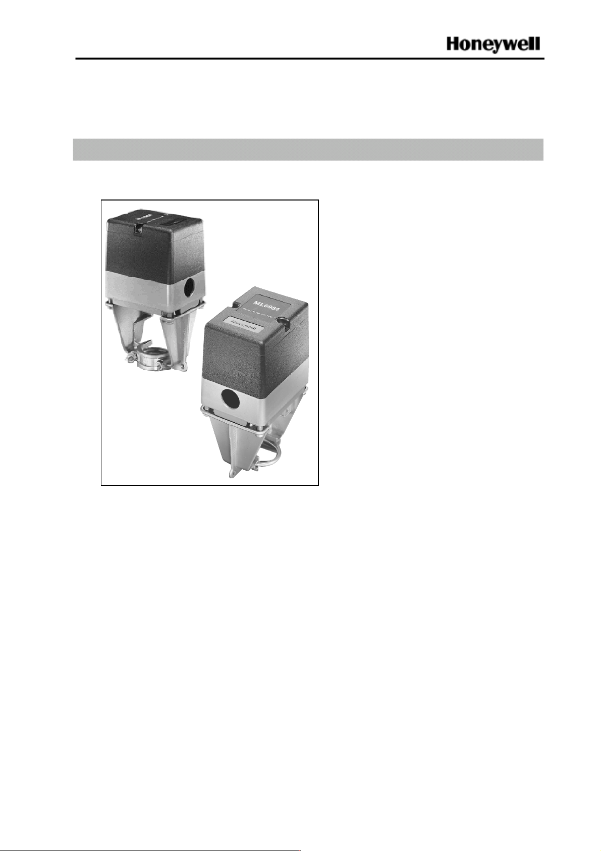
ML6984, ML7984 Series 4000
Direct Coupled Valve Actuators
PRODUCT DATA
FEATURES
• Self-contained, motorized valve linkage
• NEMA 3R cover for outdoor installation
• Linkage self-adjusts to valve stroke from 13 mm
(1/2”) to 25 mm (1”)
• DIP switches select various input configurations
• LED status indication
• Floating models compatible with 3-wire control
systems
• Strong valve seat closing force 710 N (160 lbs.)
• Electronic current sensing provides nternal
protection and positive fully closing force
• Compact size for easy installation in confined
area
• Allows the use of one common transformer power
supply for multiple actuators and controllers
• One device for either 24 Vac or 28 Vdc power
supply application
APPLICATION
The ML6984 and ML7984 are self-contained,
self-adjusting, linear motorized valves that mount directly
onto V501 1 two-way and V5013 three-way globe valves,
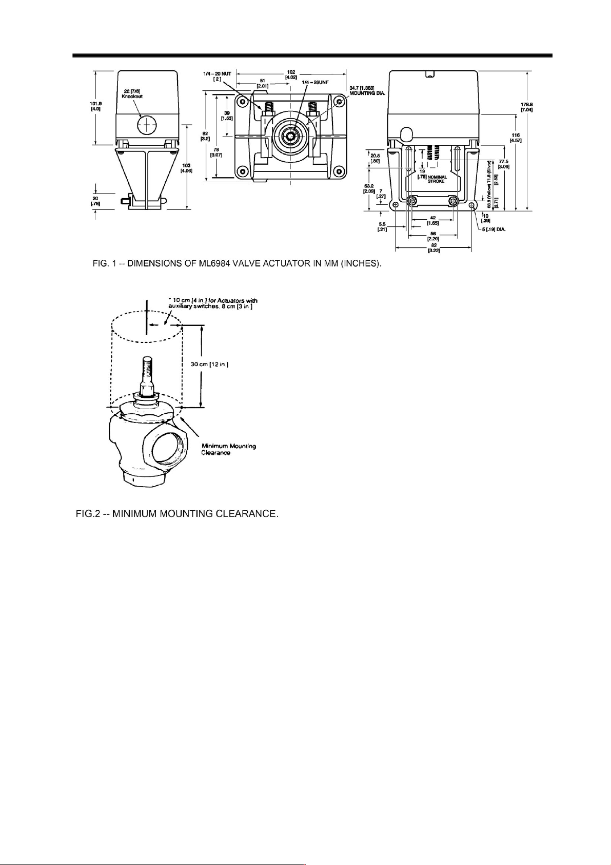
providing linear travel (stem lift) between 13 mm (1/2”)
and 25mm (1”).
ML6984 is for use with low voltage SPDT Series
20 (on-off) and Series 60 (floating) electro-mechanical
or electronic controllers. ML7984 is for use with Series
70 2-10 Vdc, 4-20 mA, electronic series 90, 135 Ω and
modulating controllers.
• Field-addable auxiliary switches available
• Field-addable position feedback option available
Contents
Specifications............................................................2
Order information..................................................... 2
Installation................................................................ 3
Wiring Schematics....................................................4
Operation ................................................................11
Checkout.................................................................12
Troubleshooting ......................................................13
PCY 06/99
© Honeywell Ltd. 1999 Printed in Canada 95C-10939
Page 2

ML6984, ML7984 DIRECT COUPLED VALVE ACTUATORS
Shipping Weight:
SPECIFICATIONS
Approx. 1 kg (2.2 lbs)
IMPORTANT:
The specifications given in this publication do not include
normal manufacturing tolerances. Therefore, an individual
unit may not exactly match the listed specifications. Also,
this product is tested and calibrated under closely
controlled conditions and some minor differences in
performance can be expected if those conditions are
changed.
Ambient Rating:
Operating Temperature:
0°C to 55°C (32°F to 130°F)
Shipping Temperature:
-40°C to +65°C (-40°F to 150°F)
Relative Humidity:
15% to 95% at 40°C (104°F) non-condensing
NEMA-3R/IP54 cover for outdoor installation
Acoustic Noise:
55 dBA max. Sound Pressure Level at 1 m (39")
distance.
Electrical Ratings:
Power supply/consumption:
24V (+10%, -15%), 50/60 Hz or 28 Vdc +/- 10%
6VA(Running), 12 VA(Valve seating)
Inputs:
M7984 - 2 -10 Vdc (1 mA)
M6984 - 25 mA 24 Vac
Input Imdepance for the ML7984:
Voltage Model — 20 KΩ
Current Model — 237 Ω
Accessories/Parts:
272630A—Auxiliary switch assembly (1-SPDT)
272775—Replacement motor brush kit
40003793-005—Mounting hardware bag assembly
272630D—Electronic low voltage auxiliary switch,
position feedback assembly
272822—Resistor kit for multiple Series 90 application
and for ML7984 to replace the old ML784 (4-20 mA)
43196000-001 High temperature kit
272629A mounting adapter for V5045 valves
Mechanical Ratings:
Stroke—Between 1/2” (13 mm) and 1” (25 mm), self-
adjusting
Bonnet—1 3/8” (35 mm)
Stroke timing—Nominal 63 seconds for 3/4" stroke,
proportional to stroke length at 24 Vac
Closing Force—710 N (160 lbs.) minimum at 24Vac.
Force varies 22 N/V (5 lbs./volt).
Performance Specifications:
Minimum Signal Input Duration: 200 ms
Life Expectancy — (at rated load and power conditions)
50,000 full stroke cycles plus 1,000,000 repositions of
10% stem travel or 10 years, whichever occurs first.
Hysterysis — 5%
Short and rapid cycling/repositioning will result in possible
device lock-up or reduced service life.
ORDERING INFORMATION
When purchasing replacement and modernization products from your wholesaler or distributor, refer to the price
sheets for complete ordering number, or specify—
1. Model number.
2. Valve body type and model number.
3. Accessories, if desired.
If you have additional questions, need further information, or would like to comment on our products or services,
please write or phone:
1. Your local Honeywell Home and Building Control Sales office (Check white pages of your phone directory).
2. Honeywell Customer Care
1885 Douglas Drive North
Minneapolis, Minnesota 55422-4386
In Canada—Honeywell Limited/Honeywell Limitée, 35 Dynamic Drive, Scarborough, Ontario M1V 4Z9
International Sales Offices in all principal cities of the world. Manufacturing in Australia, Canada, Finland, France,
Germany, Japan, Mexico, Netherlands, Spain, United Kingdom, U.S.A.
2
Page 3
ML6984, ML7984 DIRECT COUPLED VALVE ACTUATORS
INSTALLATION
When Installing This Product...
1. Read this instructions carefully. Failures to follow
them could damage the product or cause a
hazardous condition.
2. Check ratings given in instructions and on the
product to ensure the product is suitable for your
application.
3. The installer must be a trained, experienced service
technician.
4. After installation is complete, check out product
operation as provided in these instructions.
5. DO NOT electrically operate the actuator before
assembly to the valve because damage not
apparent to the installer may occur.
IMPORTANT
• Before installing the valve, raise and lower the valve
stem to make sure that the valve stem operates
freely. Impaired stem operation can indicate that the
stem was bent by rough handling. This condition can
require replacing the valve.
• Protect the stem from damage due to bending or
scratching.
Proper Use
The valves are to be installed by skilled personnel and in
strict accordance with the installation instructions and local
regulations. Honeywell assumes no responsibility for damages or injuries resulting from non-compliance with installation instructions or standard good practice when mounting,
operating, or maintaining the valves, even if not expicitly
mentioned in the installation instructions. Observe all safety
practices when working with steam systems.
Mounting:
1. Ensure that the valve body is installed correctly, that is,
the arrow points in the direction of the flow.
2. Although the actuator can be mounted in any position, it
is preferable that it is mounted above the valve body . This
will minimize the risk of damage to the actuator in the
event of condensation or a valve gland leak.
NOTE: NEMA 3R rainproof rating only applies to
actuators mounted vertically . Cover has been treated
with UV stabilizers for outdoor applications. Weatherproof conduit fittings approved for outdoor and wet
locations must be used to maintain NEMA 3R rating.
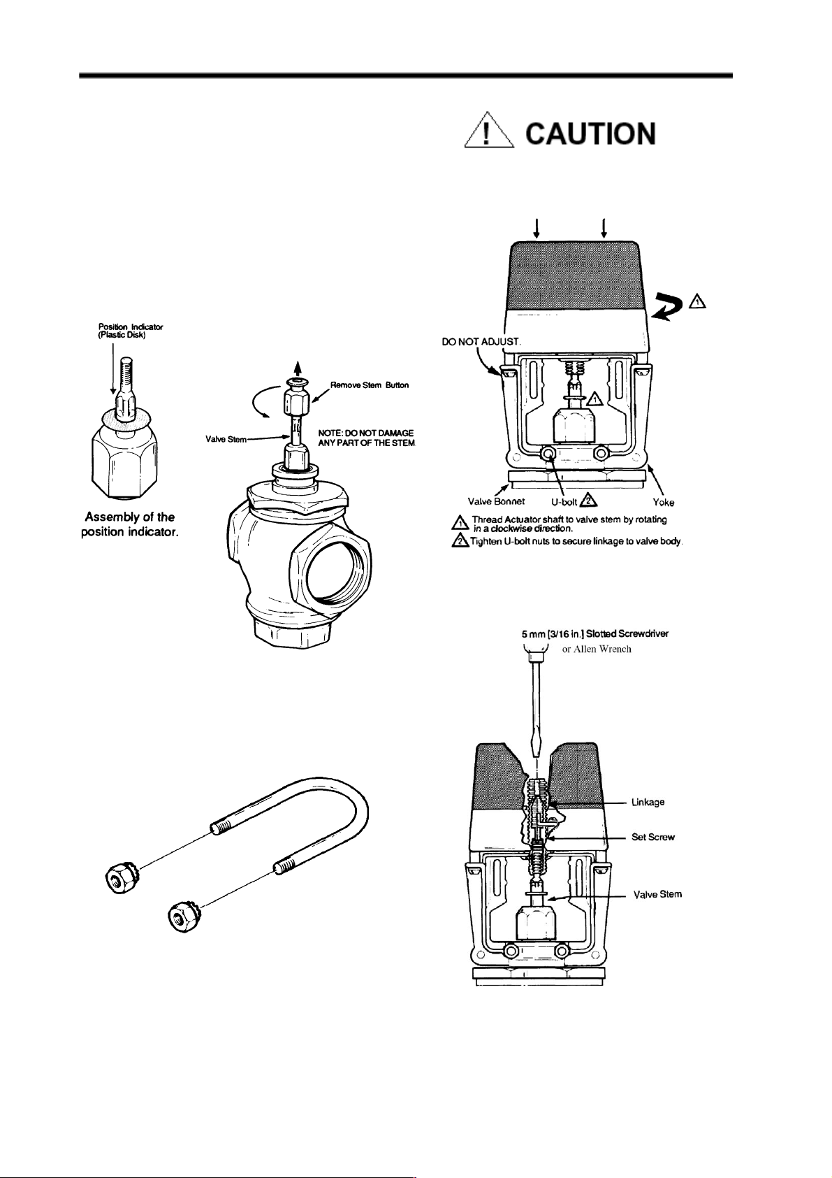
3. Remove the stem button (Fig. 3) from the valve stem.
Save the set screw inside the stem button for later
installation. The button itself is not needed.
4. Slide the position indicator (plastic disk or rubber Oring)
over the valve stem. (See inset, Fig. 3) Indicator will selfalign to the marking on the yoke after complete operating
cycle.
Assembly of ML_984 Actuator to the valve:
1. The drive shaft of the ML_984 Actuator has a 1/4-28 UNF
threaded hole to link with the valve stem. Slide the yoke
over the valve bonnet (Fig. 4)
2. Thread the ML_984Actuator drive shaft onto the valve
stem all the way, until it is completely attached (with no
threads showing), by turning the valve actuator in a
clockwise direction, as viewed from above (depending
on the valve models, use a pin or wrench to keep valve
stem from turning). Note that the valve actuator is shipped
with drive shaft in the mid-position.
3. Care should be exercised when using tools on the valve
stem during tightening. (Fig.4) DO NOT damage the
threads or other parts of the stem.
4. Orient the conduit hole to the most desirable direction,
then tighten the LOCKNUTS on the U-bolt.
3
Page 4
ML6984, ML7984 DIRECT COUPLED VALVE ACTUATORS
5. Remove the plastic cover from the ML6984 by loosening
the two screws located on the top (Note: These screws
are captive. Rotate three complete revolutions to remove
cover ). Drop either Slot Headed or Allen Hex type of set
screw (both are included in the plastic bag ) into the top of
the shaft, slotted/ Hexed side up. Or use the set screw
from the valve stem button.
6. Depending on which type of set screw was used, with a
5 mm (3/16") Slotted screwdriver or 1/8"x 6" Allen wrench
(included in the plastic bag), tighten the set screw to
lock valve stem in place (Fig. 6).
For proper valve operation, valve stem must be threaded
into the actuator all the way (with no threads showing)
and locked in place with the set screw provided.
FIG. 3 — PREPARATION FOR VALVE ASSEMBLY
FIG. 5 — U-BOLT ASSEMBLY
FIG. 4 — ASSEMBLY OF ML6984A TO
FIG. 6. — LOCKING ML6984A DRIVE SHAFT TO
VALVE STEM
4
Page 5
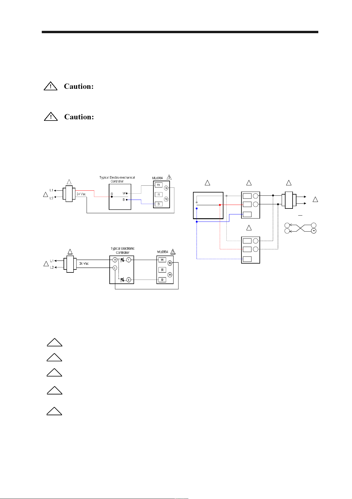
ML6984 Wiring
Wiring
ML_984 actuators are designed to operate from a Safety Extra Low Voltage, Class II power source. A 7/8” wiring hole
is provided for attaching flexible conduit where required by local codes. When installing outdoors, weatherproof conduit
fittings approved for outdoor and wet locations must be used.
Electrical Shock or Equipment Damage Hazard. Can Shock individuals or short equipment circuitry.
Disconnect power supply to the actuator to prevent electrical shock and equipment damage, or remove and cap the air
line to the actuator.
(in all cases when wiring a ML_984 Actuator)
In multiple actuators connection, power supply to all actuators must be connected in a TRUE parallel fashion to reduce
excessive voltage drop. DO NOT “daisy chain” i.e. connected to one actuator then branched to another.
Operation
The recommended valve actuator power source is a Safety Extra-Low Voltage (SELV) Class II, 24V transformer or
regulated 28Vdc across terminals T5 & T6. Internal circuitry provides dc power for the electronic sensing and drive
motor circuits.
2
1
FIG. 7A — 3-WIRE CONTROL OF ML6984 WITH
SERIES 60 CONTROLLER
2
1
FIG. 7A — 3-WIRE CONTROL OF ML6984 WITH
ELECTRONIC CONTROLLER
For Figures 7A, 7B and 7C the following apply:
Power supply provides overload protection and disconnect means.
1
Typical SPDT Controller
W
BR
4
ML6984
W
R
B
4
ML6984
W
R
B
T6
24 Vac
T5
T6
T5
23
28 Vdc
T6
T5
FIG. 7B — 5-WIRE CONTROL OF ML 6984
L1
1
L2
OR
+
Allow 0.5 amps maximum for each device. Actuators and controller can share same transformer
2
providing the VA rating of the transformer is not exceeded and proper phasing is observed.
SPDT controller can be a low voltage Series 20 “on-off” or Series 60 “floating” (tri-state) type.
3
Multiple actuators controlled by a common controller in parallel must be wired so that they all travel in the
4
same direction. Reverse acting actuators will NOT operate reliably in combination with direct acting
units.
5-wire installation is required with the 272630E feedback/auxiliary relay accessory.
5
5
Page 6
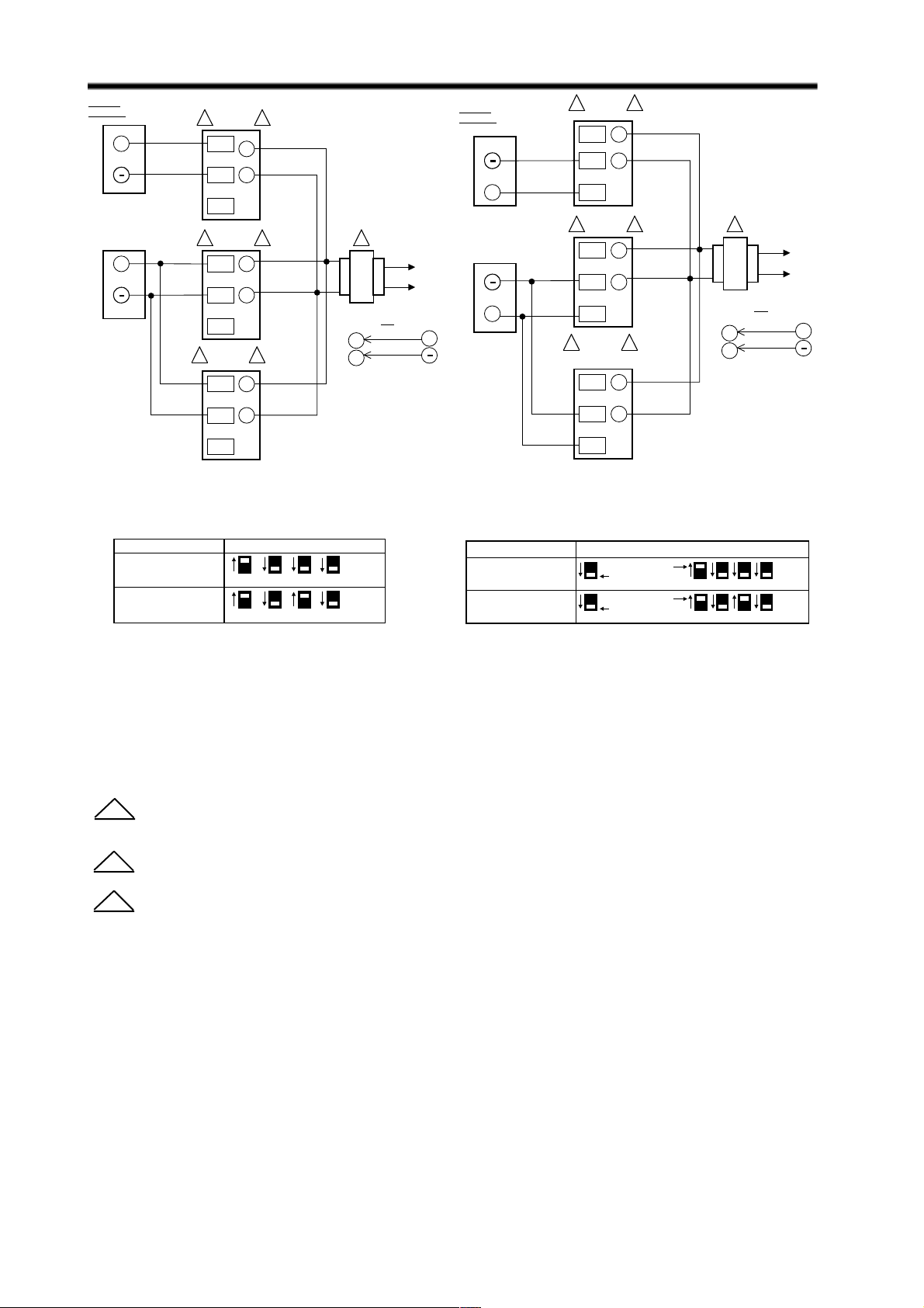
ML7984 Wiring
3 ML7984
L1
L2
1
R
W
C
T6
T5
R
W
C
T6
T5
OR
R
W
C
T6
T5
2
3 ML7984 2
3
ML7984
(SLAVE)
2
SIGNAL
SOURCE
24 Vac
+
+
+
T6
T5
28 Vdc
SIGNAL
SOURCE
+
3 ML7984
R
W
C
2
T6
T5
1
+
3 ML7984 2
T6
R
24 Vac
T5
W
C
3 ML7984 2
T6
R
T5
W
C
T6
T5
FIG. 8 — ML7984 WIRING WITH 10
VDC ANALOG CONTROL SIGNAL
FUNCTION DIP SWITCH CONFIGURATION
1000
2-10 Vdc Direct Acting
1010
10-2 Vdc Reverse Acting
1 2 3 4
1 2 3 4
On (1)
Off (0)
On (1)
Off (0)
OR
28 Vdc
L1
L2
+
FIG. 9 — ML7984 WIRING WITH 20mA
ANALOG CONTROL SIGNAL
FUNCTION DIP SWITCH CONFIGURATION
1
1
Master actuator
Slave actuator
Master actuator
Slave actuator
223
1
1
4
On (1)
Off (0)
4
3
X000
4-20 mA Direct Acting
X010
20-4 mA Reverse Acting
For Figures 8 and 9 the following apply:
1
2
3
NOTE:
Always turn power off before setting the DIP switches.
Allow 0.5 amps maximum for each device. Actuators and controller can share same transformer providing
the VA rating of the transformer is not exceeded and proper phasing is observed.
“T5” and “W” terminals are factory connected internally. Device is compatible with the 3-wire control system.
Use configuration DIP switches to select device functions: Direct acting function ( actuator stem moves
upwards with signal increases ) or Reverse acting function ( actuator stem moves downwards with signal
increases ).
6
Page 7
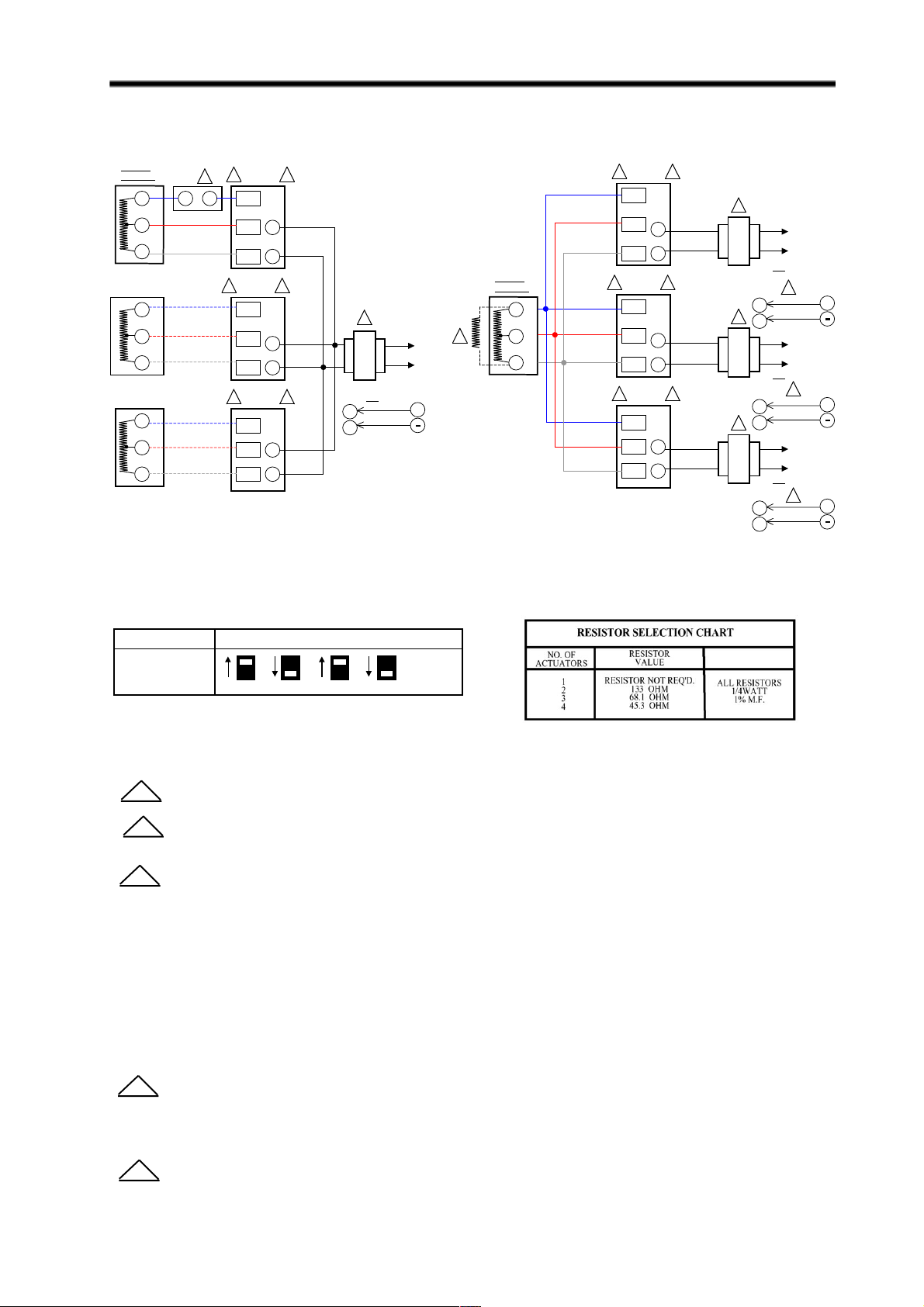
FIG. 10 — ML7984 WIRING WITH 135Ω (SLIDEWIRE) CONTROLLERS
ML7984 Wiring
B
R
W
B
R
W
B
R
W
MODULATING
LIMIT
4
R W
2
2
ML7984
2
ML7984
B
R
W
B
R
W
ML7984
B
R
W
3
T6
T5
3
1
T6
24 Vac
T5
3
T6
T5
OR
T6
28 Vdc
T5
L1
L2
+
SIGNAL
SOURCE
FIG. 10A — ML7984 WIRING WITH COMMON
TRANSFORMER, INDIVIDUAL CONTROLLERS
2
SIGNAL
SOURCE
B
4
R
W
3ML7984
B
R
T6
24 Vac
T5
W
3ML79842
B
R
T6
24 Vac
T5
W
3 ML79842
B
T6
R
W
24 Vac
T5
FIG. 10B — ML7984 WITH INDIVIDUAL
TRANSFORMERS, COMMON CONTROLLER
1
L1
L2
OR
2
28 Vdc
L1
L2
2
28 Vdc
L1
L2
2
28 Vdc
+
+
+
T6
1
T5
OR
T6
T5
1
OR
T6
T5
FUNCTION DIP SWITCH CONFIGURATION
1010
Direct Acting
21 3 4
On (1)
Off (0)
For Figures 10A, 10B, 11A and 11B the following apply:
1
3
NOTE:
1) Turn power off before setting the DIP switches.
2) For common transformer and common controller application, please consult the factory.
Allow 0.5 amps maximum for each device.
Do not mix M984/6 or Modutrol Motors with the ML7984 in the same circuitry.
2
Use configuration DIP switches to select device functions: Direct acting function (actuator stem moves
upwards with signal increases) or Reverse acting function (actuator stem moves downwards with signal
increases).
*Series 90 (mech/electronic) operation can be reversed without changing wiring by using DIP switch #3
(opposite as shown).
For Figure 10A only:
4
Maximum resistance per control circuit of 280 Ω.
For Figure 10B only:
Use Resistor Kit part # 272822
4
7
Page 8
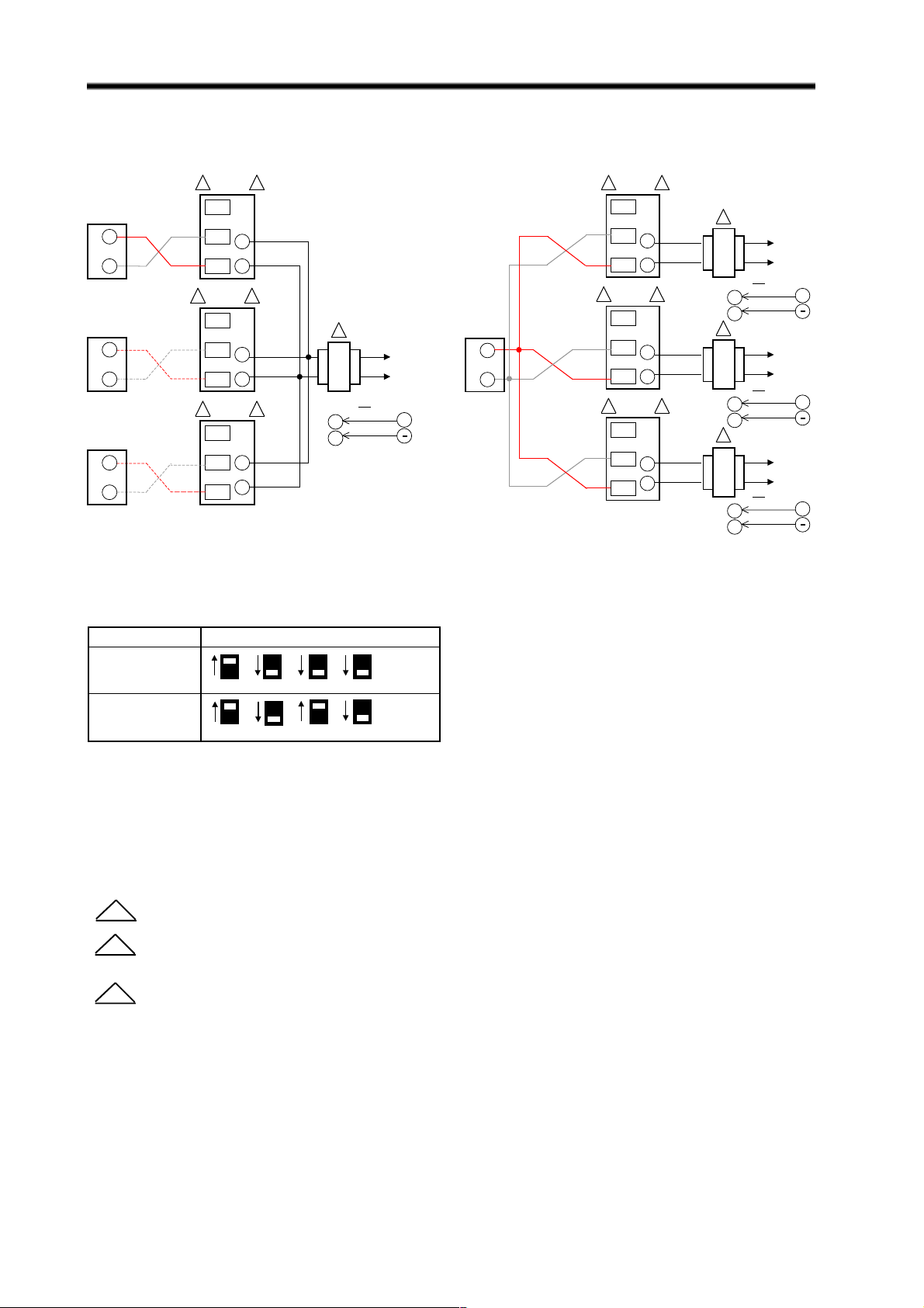
ML7984 Wiring
FIG. 11 — ML7984 WIRING WITH ELECTRONIC SERIES 90 “SUPERMOD” CONTROLLERS
ELECTRONIC
SERIES 90
(W973, T775,
H775, W7100)
R
W
NOTE:
Polarity sensitive,
check conn ections W
to R, R to W
R
W
R
W
2
3ML7984
B
R
T6
T5
W
3ML79842
B
R
T6
24 Vac
T5
W
3ML79842
B
T6
R
T5
W
1
L1
L2
OR
28 Vdc
+
T6
T5
FIG. 11A — ML7984 WITH COMMON
TRANSFORMER, INDIVIDUAL CONTROLLERS
ELECTRONIC
SERIES 90
(W973, T775,
H775, W7100)
R
W
NOTE:
Polarity sensitive,
check connections
W to R, R to W
2
3ML7984
B
R
T6
24 Vac
T5
W
3ML79842
B
R
T6
24 Vac
T5
W
3ML79842
B
R
T6
24 Vac
T5
W
FIG. 1 1B — ML7984 WITH INDIVIDUAL
TRANSFORMERS, COMMON CONTROLLER
1
L1
L2
OR
28 Vdc
OR
28 Vdc
OR
28 Vdc
+
L1
L2
+
L1
L2
+
T6
T5
1
T6
T5
1
T6
T5
FUNCTION DIP SWITCH CONFIGURATION
1000
Direct Acting
21 3 4
1010
Reverse Acting
3 4
21
*Series 90 (mech/electronic) operation can
be reversed without changing wiring by
using DIP switch #3 (opposite as shown).
For Figure 11A and 11B only:
Allow 0.5 amps maximum for each device.
1
Do not mix M984/6 or Modutrol Motors with the ML7984 in the same circuitry.
2
Use configuration DIP switches to select device functions: Direct acting function ( actuator stem
moves upwards with signal increases ) or Reverse acting function ( actuator stem moves downwards with
3
signal increases ).
On (1)
Off (0)
On (1)
Off (0)
8
Page 9
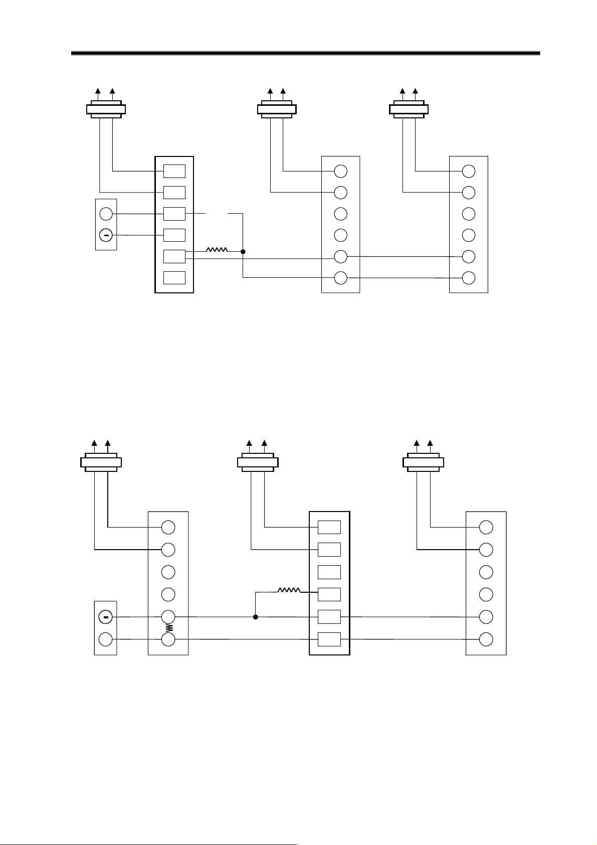
ML7984 Wiring
L1 L1 L1L2 L2 L2
+
ML7984A3xxx
New Master
T6
T5
C
B
W
R
R1=12 KΩ
WWWW
R2=3 KΩ
NOTE:
ML7984A3xxx
Slave
T6 T6
T5
C
B
W
**
R
*Previously clipped resistor
ML7984A3xxx
Slave
T5
C
B
W
R
Turn power off before
setting the DIP switches
Fig. 12 Wiring for replacing the MASTER motor in 4-20 mA multiple-actuator application.
(Use Resistor Kit part # 272822)
L1L1 L1L2L2 L2
ML7984A3xxx
Slave
T6
T5
C
ML7984A3xxx
New Slave
T6
T5
C
ML7984A3xxx
Slave
R=133Ω
B
W
+
R
Factory installed -54.9Ω
NOTE:
Turn power off before
B
W
R
*Previously clipped resistor
setting the DIP switches
Fig. 13 Wiring for replacing the SLAVE motor in 4-20 mA multiple-actuator application.
(Use Resistor Kit part # 272822)
T6
T5
C
B
W
R
*
9
Page 10

Operation
ML6984, ML7984 DIRECT COUPLED VALVE ACTUATORS
Each time actuator terminals T5-T6 are (re)powered, the
microprocessor will cycle the valve through a full stroke
to calibrate its position. Any stroke between 1/2” (13 mm)
and 1” (25 mm) will be divided into 30 equal steps. Run
time will be proportional to stroke length. The LED lights
when terminals T5-T6 are powered, and flash when the
actuator is in motion.
ML6984 Operation
The motor is controlled by a microprocessor.
Connecting B to R tells the microprocessor to cause the
actuator to drive open. Connecting W & R for one second
or longer will cause the actuator to drive closed. For
“floating” control, if R remains open, the actuator will
remain in the last position.
At the end of the valve stroke, the actuator will develop
the necessary force for positive valve close-off.
As forces are developed, the current to the motor
increases. The microprocessor stops the actuator
automatically when the motor current, and forces reach
the predetermined level.
ML6984 does not need to be powered on terminals
T5-T6, but self-calibration will not occur. The controller
must drive the valve through a cycle to calibrate stroke
length. Input signals lasting over 3 1/2 minutes will be
ignored until the switch cycles off to avoid a motor stall
condition.
1. Disconnect power supply before beginning installation
to prevent electrical shock and equipment damage.
2. All wiring must comply with applicable local electrical
codes, ordinances and regulations.
3. Make certain that the voltage and frequency of the
power supply correspond to the rating of the device.
4. DO NOT electrically operate the ML_984 actuator
before assembly to the valve because damage not
apparent to the in staller may occur.
5. DO NOT connect 24 Vac between any ML7984 signal
input terminals. DEVICE FAILURE WILL RESULT!
GENERAL NOTE:
1. The ML7984 must be field configured with the DIP
switches which are located beside the terminal block.
See wiring diagrams for details. Turn power off before
setting the DIP switches .
2. There is a short delay in actuator response upon every
signal change. This is to screen any unwanted
incoming signals.
3. For proper operation, voltage on the T5 and T6 must
not be less than 22 Vac or 24Vdc during running or
force generating stages.
REPLACEMENT NOTES
To replace ML684
ML7984 Operation
The sensing circuits respond to the signal across the
input terminals based on the configuration DIP switch
settings.
When correctly connected to the actuator, control
signal between signal input terminals is converted to a
digital run time and compared to pulse counts from the
first gear in the gear train. When these counts are equal,
the drive motor and drive shaft are stationary.
As long as the value of controlled medium remains at
the controller setpoint, the circuit is in balance, and the
actuator does not run. When the value of the controlled
medium changes, the controller output voltage is
changed causing the counters to differ. As the actuator
moves in the direction to correct the medium change,
the counters increment or decrement, and stop the
actuator when the input and gear counts agree.
At the end of the valve stroke, the actuator develops
the necessary force for positive valve close-off. The motor
stops automatically when the motor current reaches the
predetermined current and force level. The digital
counters are reset and calibrated at each end of stroke.
1. The new ML6984 is a direct replacement for the
old ML684A in single actuator or parallel multiple
actuators hook-up. The old and new actuators can
be mixed in the same electrical circuit. For multiple
actuators controlled by a common controller in
parallel, these actuators must be wired so that
they all travel in the same direction.
2. When replacing the ML684A1009 (80 lbs ) with
this new ML6984 on the V5045 valve. The already
installed valve adaptor (part # 272629A) on the
valve stem and actuator assembly is still needed.
To replace ML6874
1. The ML6984 is a direct replacement for the old
ML6874 in single actuator hook-up.
2. For parallel multiple old ML6874 actuators
applications, an isolation relay must be used
(isolation relay contacts should be placed in the
new ML6984 actuator signal input “W” and “B”
circuit).
10
Page 11

ML6984, ML7984 DIRECT COUPLED VALVE ACTUATORS
TO REPLACE ML784 or ML984:
1. The old ML784 or ML984 actuators cannot be used
with new ML7984 valve actuators in the same circuitry,
unless the old models are each powered by their own
transformer to prevent cross-talking.
2. The ML7984 is a direct replacement for all old ML784
and ML984, except:
a) When replacing the old reverse acting models, the signal
input wires to the new devices no longer need to be
reversed. Just follow the terminal polarity designations
and DIPswitch settings.
b) When replacing the old actuator which has an Electronic
Series 90 controller, i.e., T775, W973, H775, W7100,
the old interface resistor must be removed. The new
ML798 will work directly with the controller without the
external 240W resistor.
c) When replacing the old ML784 (mA model) in multiple-
actuator installations, resistor(s) will be needed. Use
Resistor Kit part # 272822 and set DIP switches
accordingly. See Figure 12 & 13.
CHECKOUT
1. Make sure the valve stem is completely screwed
into the actuator drive shaft with no threads
showing before applying power.
2. Make sure the valve stem is locked in place with
the set screw.
ML7984
3. Make sure the Configuration DIPswitches are set
correctly.
4. With 24Vac or 28Vdc power source connected to T5
and T6, actuator operation can be verified by
connecting appropriate control signal (Series 70/90)
from controller to the signal input terminals (Fig. 8-1 1).
For direct acting: A modulating action can be obtained
simply by increasing the control signal. The actuator
will travel from full stem down to full stem up. On signal
failure (disconnected /no signal), actuator defaults to
closed position. For reverse acting: Decreasing
controller signal will drive actuator from full stem down
to full stem up. On signal failure (disconnect/no signal),
actuator defaults to open position.
5. Operate the system (valve, actuator and controller) for
several cycles to ensure proper installation.
6. When checkout is completed, return the controller to
the desired setting.
NOTE: Device will ignore any input changes until it has
completed its repositioning relative to the initial signal
input.
ML6984 - 5-Wire Installation
3. Connect 24 Vac or 28 Vdc power to T5 and T6.
4. Jumper R & B. The valve stem should move up.
5. Jumper R & W. The valve stem should move
down.
6. For Floating operation, open R connection Valve
stem should remain in position.
7. Re-connect all control wiring.
8. Operate the system (valve, actuator and
controller) for several cycles to ensure proper
installation.
9. When checkout is complete, return the controller
to the desired setting.
11
Page 12

ML6984, ML7984 DIRECT COUPLED VALVE ACTUATORS
Troubleshooting Guide for ML Valve Actuator
SYMPTOM
Valve leaks or will not
close off fully.
Noisy motor
Motor overheats/
smoke/component
burnt-out
POSSIBLE CAUSES
*Wrong actuator used and/or system
pressure too high
*Actuator not properly installed
*Incorrect DIP switch settings
*Bearing failed due to overheat
*Brushes worn out
*Current sensing circuit failed or
electronic components failed
ACTIONS
*Check valve close-off rating
*Check voltage at actuator terminals
*Ensure valve stem is fully threaded into brass
drive shaft and locked in place with the set
screw.
*Check against Product Instruction Sheet
*Check for excessive temperature and replace
complete actuator
*Use high temperature bit
*Check for excessive cycling and replace
brushes (Part #272775)
Replace actuator. Make sure:
*Correct actuator used
*Properly installed
*Do not adjust any calibration pot
*Proper voltage supply
*Applied according to ML specifications
*Use high temperature bit
ML will not respond
Vdc/mA signal drops
when connected to ML
ML 6984 will not close
or lock-up when used
with T87
LED (on):
*Incorrect DIP swtich settings
*No control signal present
*Incorrect wiring connections
*Incorrect signal polarity
*Internal time delay
LED (off):
*No or Low power supply
*Error mode
*Signal degradation due to
incompatible load impedance
*T87 Colling Anticipator caused
current shunting to the ML
*Check against Product Instruction Sheet
*Check controller
*Check against Product Instruction Sheet
*Check against Product Instruction Sheet
*Allow at least 1/2 second for the ML to respond
*Check voltage on T5 & T6 terminals
*Check valve stroke
*Check Controller Output and ML Input
Impedance specifications
*Use Series 2-ML6984 (Date Code 0049) or cut
T87 Cooling Anticipator resistor
12
 Loading...