

Page 1
®
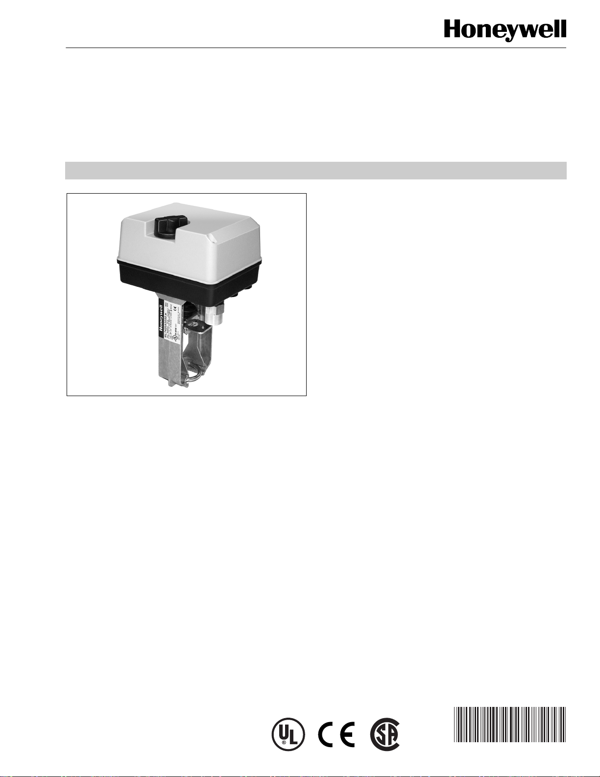
ML6420, ML7420
Non-Spring Return
Electric Linear Valve Actuators
PRODUCT DATA
FEATURES
• Quick and easy installation.
• No separate linkage required.
• Conduit connector is standard.
• No adjustments required.
• Low power consumption.
• High close-off ratings.
• Force-limiting end switches.
• Manual operator.
APPLICATION
The ML6420 Non-Spring Return Electric Linear Valve
Actuators are floating control actuators used with controllers
that provide a switched or floating single-pole double-throw
(spdt) output. These actuators operate standard Honeywell
valves in heating, ventilating, and air conditioning (HVAC)
applications.
The ML7420 Non-Spring Return Electric Linear Valve
Actuators are modulating control actuators used with
controllers that provide an analog output of 0 to 10 Vdc or 2 to
10 Vdc. These actuators operate standard Honeywell valves
in HVAC applications. An internal selector plug can be used to
reverse the direction of action.
• Synchronous motor.
• Corrosion resistant design.
• Maintenance free.
• Direct/reverse acting with ML7420.
• Position feedback signal included with ML7420.
• Selectable 0 to 10 Vdc or 2 to 10 Vdc signal input with
ML7420.
Contents
Application ........................................................................ 1
Features ........................................................................... 1
Specifications ................................................................... 2
Ordering Information ........................................................ 2
Installation ........................................................................ 3
Operation .......................................................................... 6
Checkout .......................................................................... 7
® U.S. Registered Trademark
Copyright © 2003 Honeywell International Inc.
All Rights Reserved
63-2533-2
Page 2

ML6420, ML7420 NON-SPRING RETURN ELECTRIC LINEAR VALVE ACTUATORS
SPECIFICATIONS
Models:
Run Time in
Model
ML6420A
sec at 60 Hz
30 or 60
a
ML7420A
a
Dependant on actuator model.
Stroke in
in. (mm) Description
3/4 (20) Electric Linear
Valve Actuator
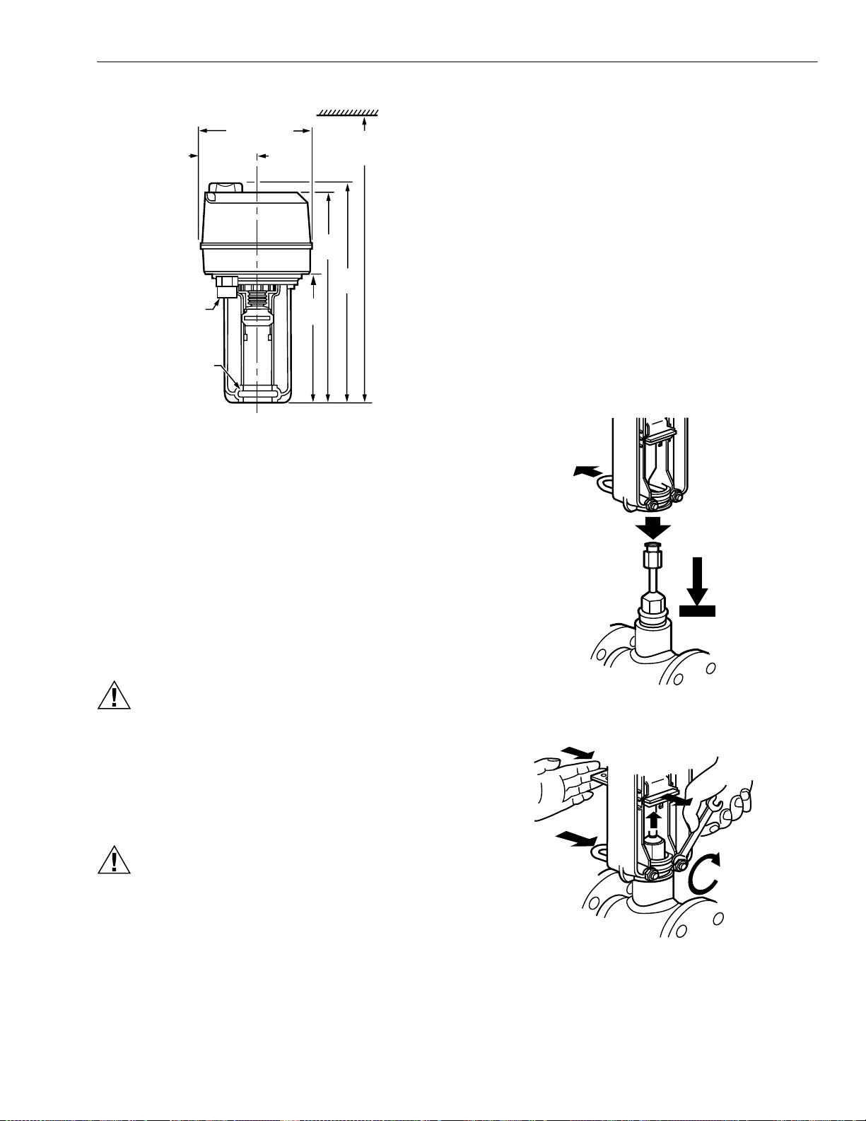
Dimensions: See Fig. 1.
Weight: 2.9 lb (1.3 kg).
Electrical Ratings:
Power Input: 24 Vac ±15%, 60 Hz.
Power Consumption:
ML6420: 6 VA maximum at 24 Vac.
ML7420: 7 VA maximum at 24 Vac.
Signal Source Output Resistance: 1K ohm maximum.
Signal Load: 1 mA maximum.
Ambient Ratings:
Temperature:
Ambient: 14°F to 122°F (-10°C to +50°C).
Storage: -40°F to +158°F (-40°C to +70°C).
Maximum Valve Medium: 300°F (150°C).
Humidity: 5 to 95 percent relative humidity, noncondensing.
Stem Force: 135 lbf (600N).
Signal Inputs (Supply Voltage Between Terminals):
ML6420:
B and 24 Vac: Drives valve stem down.
W and 24 Vac: Draws valve stem up.
ML7420: 0 to 10 Vdc or 2 to 10 Vdc.
Actuator Material:
Cover: ABS-FR plastic.
Base: PBTP-FR plastic.
Yoke: Diecast aluminum.
Actuator Stroke: 3/4 in. (20 mm).
Close-off Pressure Ratings: See Table 1.
Protection Standard: IP54.
Approvals:
Canadian Standards Association Listed.
Underwriter’s Laboratories, Inc. UL94-5V Flame Retardant.
Meets CE requirements.
Cable entry: Conduit connector and one knockout on case.
Accessories:
43191679-111 Single Auxiliary 10K ohm Potentiometer.
43191679-112 Single Auxiliary 220 ohm Potentiometer.
43191680-105 Dual Auxiliary Switch (for 24 Vac use only).
43196000-001 High Temperature Kit (1/2 to 3 in. valves).
Increases temperature range high-end to 428°F (220°C).
Table 1. Close-off ratings for ML6420, ML7420 Electric Linear Valve Actuators and Honeywell Valves (psi).
Type Valve 1/2 in. 3/4 in. 1 in. 1-1/4 in. 1-1/2 in. 2 in. 2-1/2 in. 3 in.
FlangeV5011A ——————2816
V3350/3351/3450/3451 — — — — — — 21 14
V5013B,C; V3360/3361/3460/3461 — — — — — —
NPT V5011F,G
150
a
21
b
150
b
150
b
134
b
77 49 28 16
14
a
V5011H,J 150 150 150 145 — — — —
V5011N1xxx, V5011N3xxx, V5013N 230 230 163 104 67 37
V5011N2xxx 100 100 100 100
V5013F 150 150 150 126 77 49
a
Represents maximum pressure difference between the outlet and either of the two inlets.
b
Do not exceed 100 psi with V5011G valves used in steam applications.
ORDERING INFORMATION
When purchasing replacement and modernization products from your TRADELINE® wholesaler or distributor, refer to the
TRADELINE® Catalog or price sheets for complete ordering number.
If you have additional questions, need further information, or would like to comment on our products or services, please write or
phone:
1. Your local Honeywell Automation and Control Products Sales Office (check white pages of your phone directory).
2. Honeywell Customer Care
1885 Douglas Drive North
Minneapolis, Minnesota 55422-4386
In Canada—Honeywell Limited/Honeywell Limitée, 35 Dynamic Drive, Scarborough, Ontario M1V 4Z9.
International Sales and Service Offices in all principal cities of the world. Manufacturing in Australia, Canada, Finland, France,
Germany, Japan, Mexico, Netherlands, Spain, Taiwan, United Kingdom, U.S.A.
63-2533—2 2
Page 3
ML6420, ML7420 NON-SPRING RETURN ELECTRIC LINEAR VALVE ACTUATORS
2)
1
2
5-5/15
6-5/16
/2 (13) FPT
YOKE
DIAMETER
1-3/8 (35)
M17419
(135)
2-11/16 (67)
x
(161)
5-9/16
(141)
12-11/16 (32
MINIMUM
CLEARANCE
9-3/16
(233)
9-9/16
(242)
Fig. 1. Approximate dimensions of ML6420, ML7420
Electric Linear Valve Actuator in in. (mm).
Mounting
1. Place the actuator on the valve with the U-bolt around
the valve collar. See Fig. 2.
2. Place the U-bolt against the valve collar and secure the
actuator to the valve by turning each U-bolt nut clockwise.
NOTE: To assure even pressure on the collar, first
tighten the nuts finger-tight and then alternate
turning each U-bolt nut until both are snug.
3. Push aside the stem button retaining clip and hold. See
Fig. 3.
4. Lift valve stem until the head of the valve stem button is
inside the large slot of the stem button retaining clip on
the actuator.
5. Release the stem button retaining clip to secure the
stem button. Check to make certain the stem button is
secured by the retaining clip.
6. Remove the cover from the actuator using a Phillips or
crosspoint screwdriver. See Fig. 4.
INSTALLATION
When Installing this Product...
1. Read instructions carefully. Failure to follow them could
damage the product or cause a hazardous condition.
2. Check ratings and description given in the specifications
to make sure the product is suitable for your application.
3. Installer must be a trained, experienced service
technician.
4. After installation is complete, check out product
operation as provided in these instructions.
CAUTION
Electrical Shock or Equipment Damage Hazard.
Can shock individuals or short equipment circuitry.
Disconnect power supply before installation.
Location
Install the actuator in a location that allows enough clearance
for mounting accessories and for servicing.
CAUTION
Equipment Damage Hazard.
Can damage actuator due to condensation or a
valve gland leak.
Install the actuator in a position above horizontal.
M663
Fig. 2. Attaching actuator to valve collar.
M6633
Fig. 3. Securing actuator to valve.
3 63-2533—2
Page 4
ML6420, ML7420 NON-SPRING RETURN ELECTRIC LINEAR VALVE ACTUATORS
T)
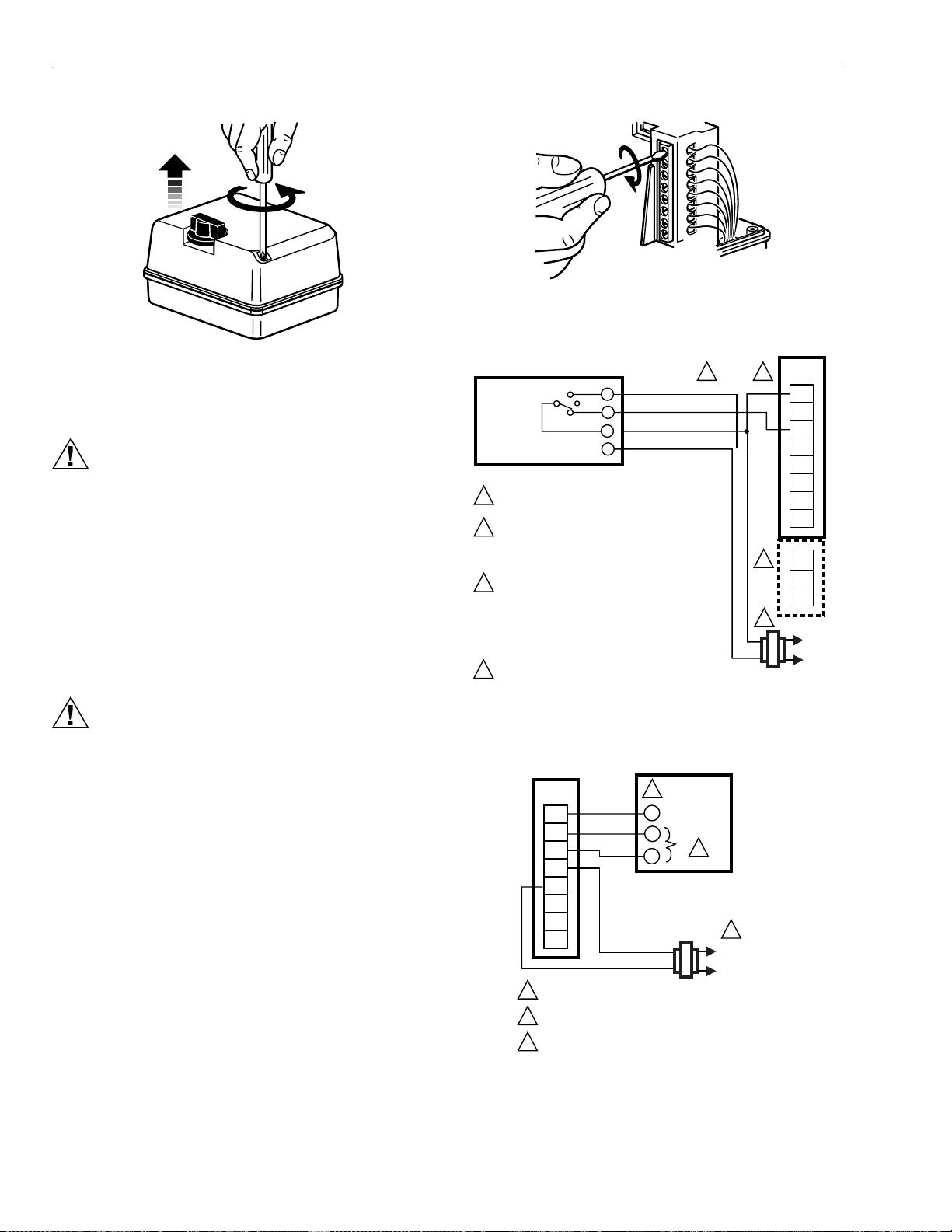
Fig. 5. Connecting power and control wiring.
M17420
Fig. 4. Removing actuator cover.
T6984 (FLOATING CONTROLLER)
Wiring
CAUTION
Electrical Shock or Equipment Damage Hazard.
Can shock individuals or short equipment circuitry.
Disconnect power supply before installation.
All wiring must comply with local electrical codes, ordinances
and regulations. Voltage and frequency of the transformer
used with the actuator must correspond with the power supply
and actuator characteristics. See Fig. 6 through 11 for typical
wiring hookups.
1. Feed power and control wires through the conduit
connector located on the bottom of the actuator case.
See Fig. 5.
1
POWER SUPPLY. PROVIDE DISCONNET MEANS
AND OVERLOAD PROTECTION AS REQUIRED.
2
ALL WIRING BLOCKS HAVE THE SAME
NUMBER OF TERMINALS (8), BUT THE ONLY
TERMINALS THAT ARE ACTIVE ON THIS
BLOCK ARE T1, T2, W, AND B.
THE T-Y-G TERMINALS ARE A THREE TERMINAL
3
WIRING BLOCK SEPARATE FROM THE MAIN
BLOCK. THEY DO NOT APPEAR ON ALL MODELS
BECAUSE THEY ARE FOR A SINGLE FEEDBACK
POTENTIOMETER (10K OR 220 OHMS). THE
REQUIRED WIRING BLOCKS ARE PART OF
THE POTENTIOMETER ACCESSORY KITS.
4
MOTOR OPEN SIGNAL DRAWS VALVE STEM
UPWARDS. MOTOR CLOSE SIGNAL DRIVES
VALVE STEM DOWNWARDS.
MOTOR OPEN
MOTOR CLOSE
24 Vac
COMMON
M6630
ML6420A,B
4
WIRING
2
STRIP
T1
T2
W
B
T
3
Y
G
1
L1
(HO
L2
M17421
CAUTION
Equipment Damage Hazard.
Conduit connection or removal can break an
unsupported connector.
When removing or attaching conduit, use a wrench to
support the motor connector.
2. Using the wiring diagram in Fig. 6, connect power and
control wires. Make sure that all wiring is correct.
3. For ML7420 only: Check the selector plugs for proper
settings. See Signal Input Failure section for details.
4. When wiring is complete, replace the actuator cover.
See Fig. 7.
5. Apply power and control signals to the actuator.
63-2533—2 4
Fig. 6. ML6420 wiring.
ML7420
WIRING
STRIP
F
+
–
T2
T1
O1
O2
1
POWER SUPPLY. PROVIDE DISCONNECT MEANS AND
OVERLOAD PROTECTION AS REQUIRED.
2
2-10 Vdc FEEDBACK SIGNAL. SEE OUTPUT SIGNAL
FEEDBACK SECTION.
3
0-10 Vdc OR 2-10 Vdc CONTROL SIGNAL. SEE SIGNAL
INPUT (+) SECTION.
2
F
(FEEDBACK)
+
–
INPUT
OUTPUT
3
1
L1
(HOT)
L2
M17422
Fig. 7. ML7420 wiring using feedback output from
a controller with a common transformer.
Page 5
ML6420, ML7420 NON-SPRING RETURN ELECTRIC LINEAR VALVE ACTUATORS
)
S
)
)
S
)
7
ML7420
WIRING
STRIP
F
2
4
1
3
6
5
+
–
T2
T1
O1
O2
1
POWER SUPPLY. PROVIDE DISCONNECT MEANS
AND OVERLOAD PROTECTION AS REQUIRED.
T775
(WITH 2-10 VDC OUTPUT)
1
2
3
L1
(HOT)
1
L2
DUAL
TRANSFORMER
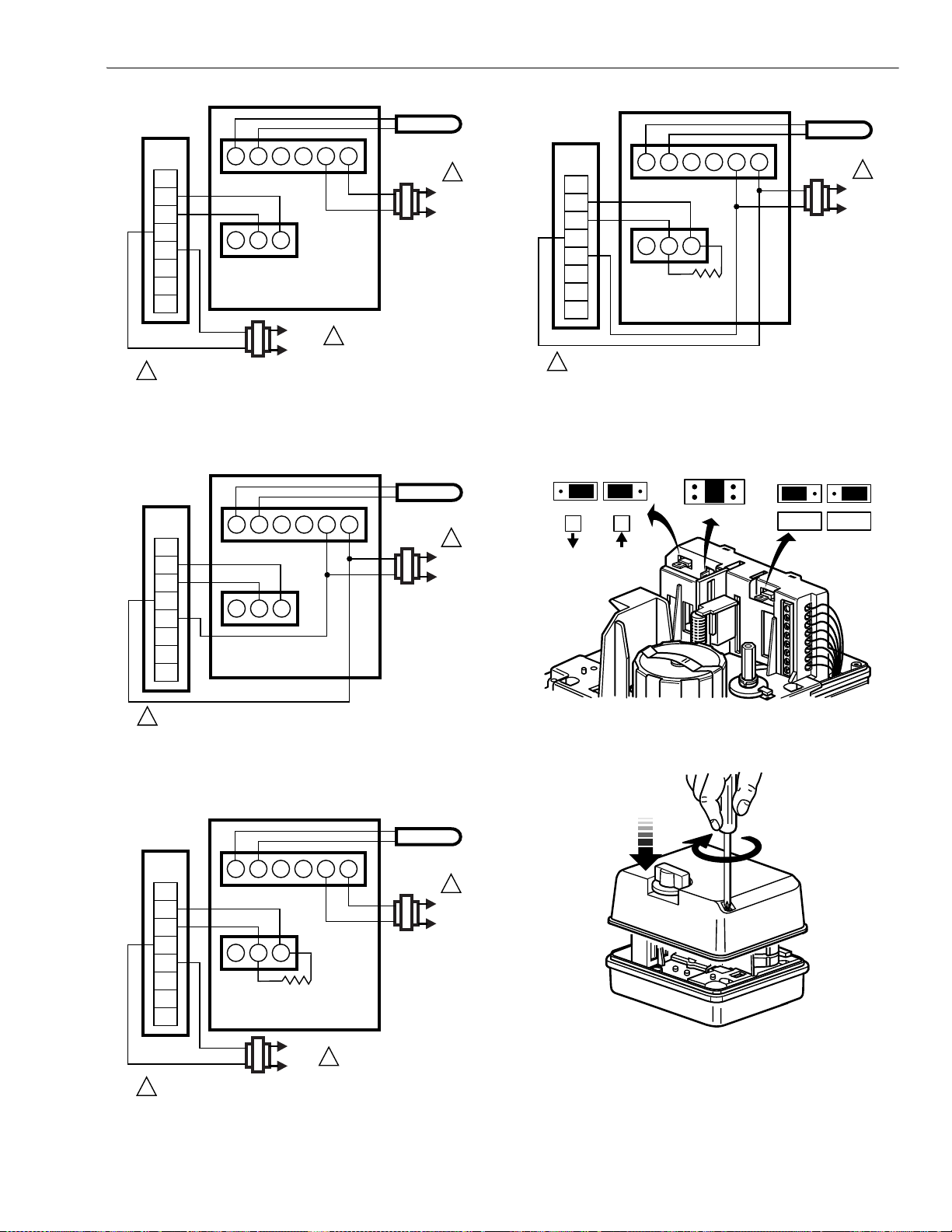
Fig. 8. ML7420 wiring using a 2 to 10 Vdc
control signal and separate transformers.
SENSOR
M17423
1
L1
(HOT
L2
SENSOR
ML7420
WIRING
STRIP
F
2
4
1
3
6
5
+
–
T2
T1
O1
O2
1
POWER SUPPLY. PROVIDE DISCONNECT MEANS
AND OVERLOAD PROTECTION AS REQUIRED.
T775
(WITH 4-20 MA OUTPUT)
1
2
3
500 OHM
RESISTOR
SINGLE
TRANSFORMER
40 VA 24 VAC
Fig. 11. ML7420 wiring using a 4 to 20 mA
control signal and a common transformer.
L1
(HOT
L2
M17426
1
ML7420
WIRING
STRIP
F
2
4
1
3
6
5
+
–
T2
T1
O1
O2
POWER SUPPLY. PROVIDE DISCONNECT MEANS
1
AND OVERLOAD PROTECTION AS REQUIRED.
T775
(WITH 2-10 VDC OUTPUT)
1
2
3
SINGLE
TRANSFORMER
40 VA 24 VAC
Fig. 9. ML7420 wiring using a 2 to 10 Vdc
control signal and a common transformer.
ML7420
WIRING
STRIP
F
+
–
T2
T1
O1
O2
1
POWER SUPPLY. PROVIDE DISCONNECT MEANS
AND OVERLOAD PROTECTION AS REQUIRED.
2
2
4
3
1
500 OHM
RESISTOR
L1
(HOT)
L2
1
3
T775
(WITH 4-20 MA OUTPUT)
6
5
DUAL
TRANSFORMER
1
SENSOR
M17424
SENSOR
M17425
1
L1
(HOT
L2
1
L1
(HOT
L2
0%
W1
W2
100%50%
0 ... 10V2 ... 10V
M1742
W3
10V
10V
Fig. 12. Location of W1, W2, and W3 selector plugs.
M17428
Fig. 13. Replacing actuator cover.
Fig. 10. ML7420 wiring using a 4 to 20 mA
control signal and separate transformers.
5 63-2533—2
Page 6
ML6420, ML7420 NON-SPRING RETURN ELECTRIC LINEAR VALVE ACTUATORS
0
Auxiliary Potentiometers
The 43191679 Auxiliary Potentiometers can be used as
feedback potentiometers and to provide remote indication of
valve position. See the Installation Instructions packed with
the potentiometers.
Auxiliary Switches
The 43191680 Dual Auxiliary Switch can be used on both the
ML6420 and ML7420 Electric Linear Valve Actuators. Switching
points are adjustable over the full length of the actuator stroke;
for example, the switch can be used to switch pumps or to
provide remote indication of any stroke position. See the
Installation Instructions packed with the auxiliary switch.
CAUTION
Equipment Damage Hazard.
Improper voltage damages the auxiliary switch
beyond repair.
Use the 43191680 Dual Auxiliary Switch only with
24 Vac applications.
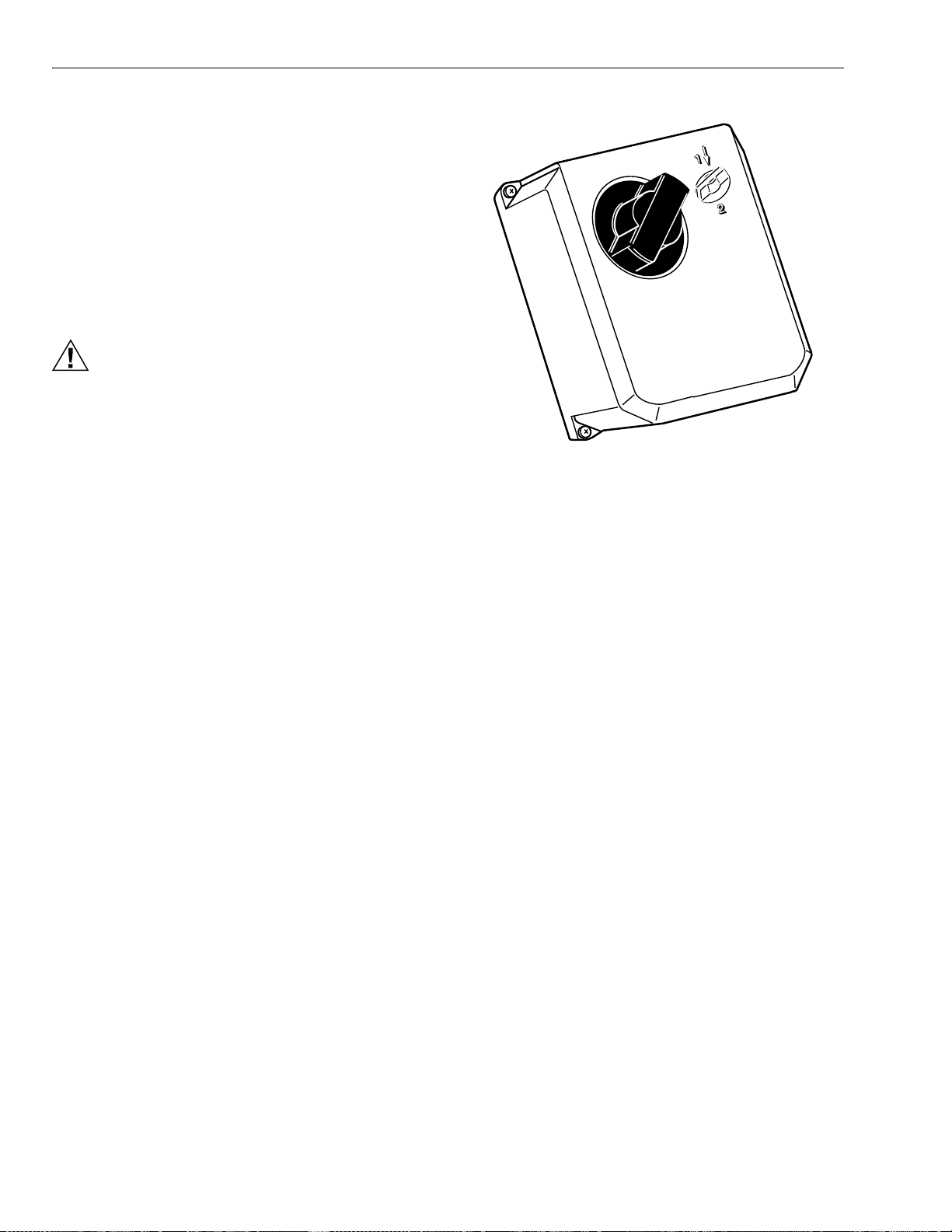
Fig. 14. Manual operator knob.
M664
OPERATION
General
In the actuator, the drive of a synchronous motor is converted
into the linear motion of the actuator stem by using a spur
gear transmission. A button retainer clip connects the actuator
stem to the valve stem.
Manual Operation
The ML6420 and ML7420 are equipped with a manual
operator knob (see Fig. 14) to open or close the valve in the
event of power failure:
1. Turn off or disconnect the power supply before manually
operating the actuator.
2. Push down on the manual operator knob and turn the
knob:
a. Counterclockwise to drive the stem downward.
b. Clockwise to draw the stem upward.
IMPORTANT
Manual operation allows very high closing force that
can jam the actuator spindle, exceed the force switch
ratings, and stop the motor. After a manual valve
close-off operation, release the spindle one turn by
turning the manual operator knob. This will ensure
automatic disengagement of the manual operator
upon power resumption.
NOTE: If the manual operator knob is not pushed in while
turned, it will rotate only a short distance before
disengaging without power resumption.
ML7420
Signal Input (+)
The analog input signal (+) range is set at the factory to 0 to
10 Vdc. Changing the position of the W2 selector plug sets the
range to 2 through 10 Vdc. Selector plugs W1, W2, and W3
are positioned on the back side of the printed circuit board.
See Fig. 12 for location of the selector plugs.
Signal Input Failure
Using selector plug W1, the actuator can be set to run to one
of three positions in event of a signal failure:
• 0% Actuator position corresponds with 0 or 2 Vdc signal.
• 50% Actuator in mid-position.
• 100% Actuator position according to 10 Vdc signal.
NOTE: W1 is factory set at the mid-position.
Output Signal Feedback (F)
An analog output signal (2 to 10 Vdc) that represents the
actual actuator stem position is available at terminal F. It can
be used for remote indication of the stem position. When the
actuator stem is fully downward, the output signal is 10 Vdc.
When the valve stem is up, the output signal is 0 or 2 Vdc.
The output of the signal does not change when the action of
the actuator is reversed using W3. See Direction of Action.
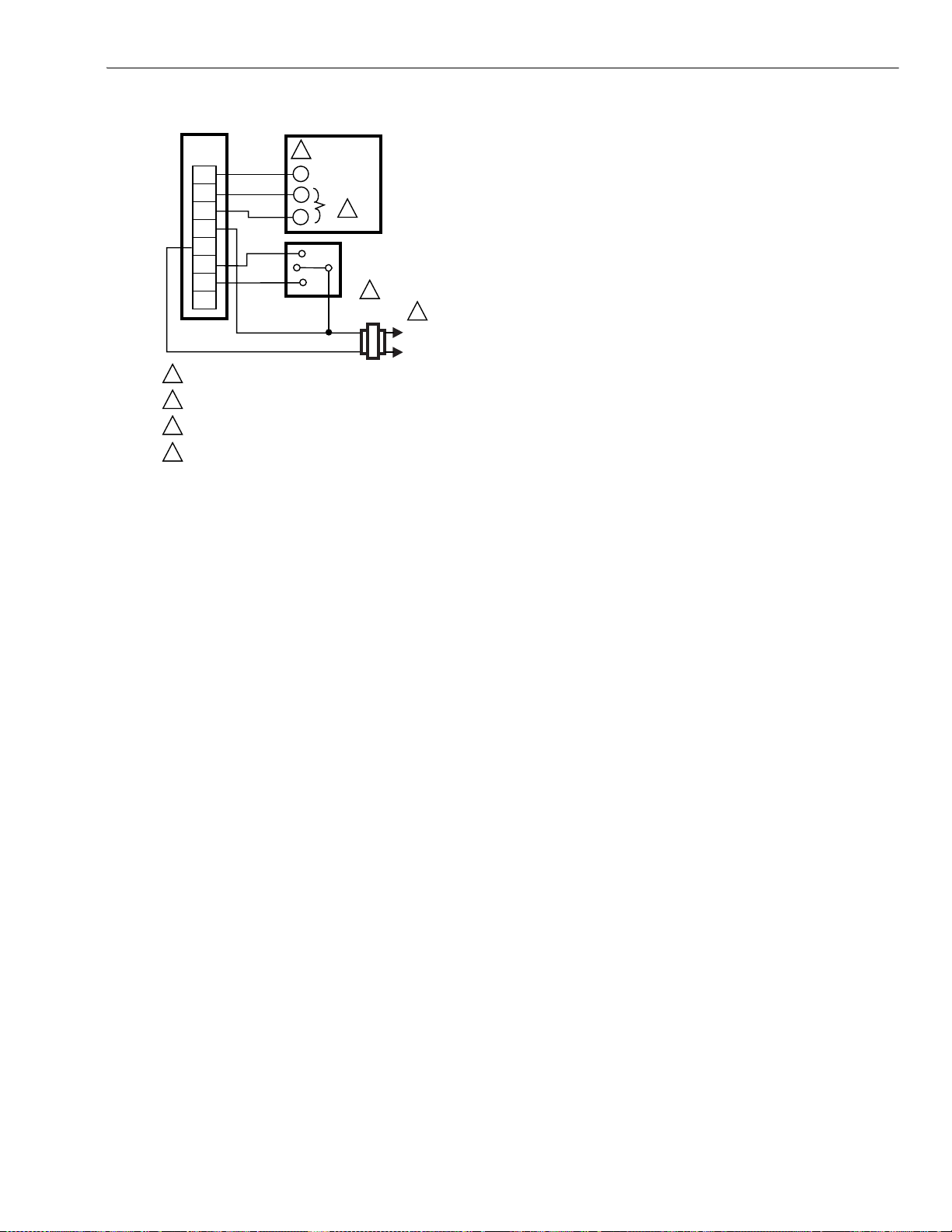
Actuator Override
To override the control signal (for freeze protection or similar
applications), connect the 24 Vac common (T2) to either
terminal O1 or O2. Connecting to terminal O1 fully extends
the actuator stem. Connecting to O2 fully retracts the actuator
stem.
63-2533—2 6
The control signal (+) is ignored when the override signal is
applied to terminal O1 or O2. This override can be achieved
with a switch or a relay. See Fig. 15.
Page 7
ML6420, ML7420 NON-SPRING RETURN ELECTRIC LINEAR VALVE ACTUATORS
)
ML7420
WIRING
STRIP
F
+
–
T2
T1
O1
O2
1
POWER SUPPLY. PROVIDE DISCONNECT MEANS
AND OVERLOAD PROTECTION AS REQUIRED.
2
2-10 Vdc FEEDBACK SIGNAL. SEE OUTPUT SIGNAL
FEEDBACK SECTION.
3
0-10Vdc OR 2-10 Vdc CONTROL SIGNAL. SEE SIGNAL
INPUT (+) SECTION.
SEE OVERRIDE SECTION FOR DETAILS ON
4
OVERRIDE OPERATION.
2
F
(FEEDBACK)
+
–
INPUT
OUTPUT
3
OVERRIDE
SWITCH
SP3T
4
Fig. 15. Connections for overriding control signal
to drive ML7420 to a specific position.
CHECKOUT
L1
(HOT
L2
M17429
Direction of Action
The direction of the actuator action can be changed by
repositioning selector plug W3, which is factory set so that the
actuator drives the valve stem down on increasing signal and
draws the valve stem up on decreasing signal. With the valve
stem up, the output signal from the feedback (F) function is
either 0 or 2 Vdc. The output of the signal does not change
when W3 is used to reverse the actuator action. See Fig. 12.
1
The actuator can be checked out either directly or by using a controller.
Direct Checkout
1. Mount the actuator for the required application; see
Controller Checkout
1. Adjust the setpoint of the controller to call for opening
Installation section.
2. Check the valve position and make sure that 24 Vac is
correctly applied to the actuator.
2. If the valve is closed, it should begin to open.
3. If the valve remains closed, move the setpoint further
3. Apply the power to the appropriate leadwires to move
the valve.
4. If the valve does not move, check for 24 Vac in the
4. If the actuator does not move, make sure the actuator is
properly installed/wired.
5. If 24 Vac is present and the actuator does not operate,
5. If the actuator installation and wiring are both correct
and the actuator does not run, replace the actuator.
6. If the wiring is correct, 24 Vac is present on the power
the valve. Observe the actuator.
toward the open setting.
actuator power input.
check the voltage across the controller leadwires to
determine if the device is miswired.
input terminals, and the actuator does not run, replace
the actuator.
7 63-2533—2
Page 8

Automation and Control Solutions Honeywell International Honeywell Europe S.A. Honeywell Latin American
Honeywell International Inc. Honeywell Limited-Honeywell Limitée Control Products 3 Avenue du Bourget
1985 Douglas Drive North 35 Dynamic Drive Honeywell Building 1140 Brussels 480 Sawgrass Corporate Parkway
Golden Valley, MN 55422 Scarborough, Ontario 17 Changi Business Park Central 1 Belgium Suite 200
M1V 4Z9 Singapore 486073 Sunrise FL 33325
Region
63-2533—2 B.B. Rev. 1-03 www.honeywell.com
Printed in U.S.A. on recycled
paper containing at least 10%
post-consumer paper fibers.
 Loading...