

Page 1
HONEYWELL
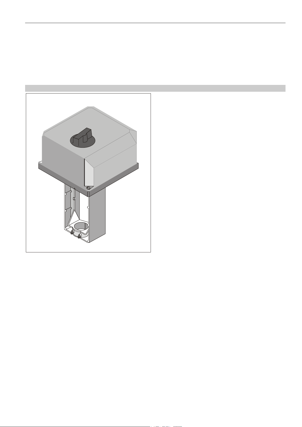
ML6421A,B
Electric Linear Valve Actuators
SPECIFICATION DATA
GENERAL
These valve actuators provide floating control and are
equipped with a synchronous motor for exact positioning.
They are suitable for use in conjunction with controls
providing switched or floating single-pole, double-throw
(SPDT) control outputs to operate Honeywell’s standard
valve series in heating, ventilation, and air conditioning
(HVAC) applications.
FEATURES
• Quick and easy installation
• No separate linkage required
• No adjustments
• Force-limiting end switches
• Manual operator
• Models for low and line voltage
• Synchronous motor
• Corrosion-resistant design
• Maintenance-free
SPECIFICATIONS
Temperature Limits
Ambient operating limits -10...+50 °C at 5...95%rh
Ambient storage limits -40...+70 °C at 5...95%rh
Medium valve temperature Max.+150 °C (+220 °C with
High-Temperature Kit)
Safety
Protection class, 24V models III according to EN60730-1
Protection class, 230V models I according to EN60730
Protection standard IP54 according to
EN60529
Flame retardant housing V0 according to UL94, with
metal cable gland
Noise level ≤45dB(A)
Wiring
Wiring terminals 1.5 mm
Cable entry M20x1.5 and knock-out for
PG11
Material
Cover ABS
Yoke and base Aluminum diecast
2
Weight 2.0 kg
Dimensions See Fig. 1 and Fig. 2
® U.S. Registered Trademark EN0B-0414GE51 R0207
Copyright © 2007 Honeywell Inc. All Rights Reserved.
Page 2

ML6421A,B ELECTRIC LINEAR VALVE ACTUATORS
model number ML6421A3005 ML6421B3004 ML6421A3013 ML6421B3012
supply voltage
power consumption
signal input 1
signal input 2
stroke
run-time @ 50 Hz
nominal stem force
24 Vac (±15%); 50/60 Hz
13 VA (50 Hz) / 15 VA (60 Hz) 11 VA (50 Hz) / 13 VA (60 Hz)
Supply voltage between terminals 1 and 24 V~;
actuator stem extended: two-way valve closed;
three-way valve port A - AB open.
Supply voltage between terminals 2 and 24 V~;
actuator stem retracted: two-way valve open;
three-way valve port A - AB closed.
20 mm 38 mm 20 mm 38 mm
1.9 min 3.5 min 1.9 min 3.5 min
1800 N
230 Vac (+10%/-15%); 50/60 Hz
Supply voltage between terminals N and Ph 1;
actuator stem extended: two-way valve closed;
three-way valve port A - AB open.
Supply voltage between terminals N and Ph 2;
actuator stem retracted: two-way valve open;
three-way valve port A - AB closed.
OPERATION
General
The drive of the synchronous motor is converted into linear
motion of the actuator stem by using a worm gear transmission. The actuator stem is connected with the valve
stem by a button keyed retainer connection.
Via installed microswitches, the internal force sensor
switches off the actuator precisely when the nominal stem
force is reached.
Manual Operation
The actuators are equipped with a manual operator used in
case of power failure. Manual operation is only allowable
after the power supply is switched off or disconnected.
To operate, push the manual operator knob down and turn
counter-clockwise to move the stem downwards and
clockwise to move the stem upwards. If the actuator returns
to automatic control, the manual operator knob unlocks
automatically.
NOTE: Manual operation allows a very high closing force
capable of jamming the actuator spindle and
exceeding the rating of the force switches, so that
the motor cannot move.
Therefore, after a manually close-off operation, it
is necessary to release the spindle one turn by
turning the manual operator knob, so that the
manual operator will automatically disengage on
power resumption.
Accessories
The following accessories are available upon request:
Auxiliary Switches
The actuators can be equipped on-site with an auxiliary
switch unit having two switches (see Fig. 4). Their switching
points are adjustable over the full length of the actuator
stroke. The switches can be used to switch pumps or to
provide remote indication of any stroke position.
A cable gland PG11 is delivered with the unit.
Auxiliary Potentiometer
The auxiliary potentiometers (see Fig. 4) are available for
mounting on site. They can be used as feedback potentiometer and/or to provide remote indication of the valve
position. A cable gland PG11 is delivered with the unit.
accessory-type stroke order no.
250 Vac / 5 (3) A (package
contains two SPDT switches)
(full range: 220 Ω; operating
range: 135 Ω)
single auxiliary potentiometer
(10k Ω)
20 mm auxiliary switches
38 mm
20 mm 43191679-001 single auxiliary potentiometer
38 mm 43191679-002
20 mm 43191679-007
38 mm 43191679-008
43191680-002
High Temperature Kit
Two options for applications with medium valve temperatures of +150...+220 °C are available for the following
valves:
order number
High-Temperature Kit
43196000-001
43196000-002
43196000-038
valve DN
V5011A/V5011K
V5013A/V5013G
V5011R/V5013R
V5328A/V5329A
V5011A
V5013A/V5013G
V5328A/V5329A
V5049A
V5050A
V5328A
V5016A
V5025A
V5049A (PN25/40)
V5050 (PN16)
V5050 (PN25/40)
15 – 40
15 – 40
15 – 50
15 – 32
50
50
40 – 80
15 – 65
15 – 80
100 – 150
100 – 150
100 – 150
80 – 100
100 – 150
100
EN0B-0414GE51 R0207 2
Page 3

ML6421A,B ELECTRIC LINEAR VALVE ACTUATORS
CLOSE-OFF PRESSURE RATINGS
stroke 20 mm 38 mm
valve mm 15 20 25 32 40 50 65 80 80 100 125 150
size inch 1/2 3/4 1 1 ¼ 1 ½ 2 2 ½ 3 3 4 5 6
valves close-off pressure ratings (in kPa)
V5011R 1600 1600 1500 850
V5011K 1600 1600
V5013R 1600 1600 1500 850
V5015A 150 120 80
V5025A 2500 2500 2500
V5328A 1600 1600 1600 1600 1300 750 470 230
V5329A (PN16) 1000 1000 1000 650 400
V5329C (PN6) 600 600 600 400
V5049A 2500 2500 2500 2000 1300 750 500 230 230 90 90
V5050A 2500 2500 2500 2000 1300 750 500 230 230 90 90
= Use 600 N actuator
For details on the valves, see the following Specification Data No.:
V5011R EN0B-0064GE51 5049A EN0B-0238GE51
V5011S EN0B-0085GE51 V5329A/5050A EN0B-0310GE51
V5016A EN0B-0440GE51 V5025A EN0B-0442GE51
V5095A EN0B-0412GE51 V5013R EN0B-0065GE51
V5328A EN0B-0432GE02
DIMENSIONS
178x (178)
64
178x (178)
64
additional
knock-out for
cable fitting:
18.9 (PG11)
142
239
360
264
additional
knock-out for
cable fitting:
18.9 (PG11)
301
204
430
326
Fig. 1. ML6421A (dimensions in mm)
3 EN0B-0414GE51 R0207
Fig. 2. ML6421B (dimensions in mm)
Page 4

ML6421A,B ELECTRIC LINEAR VALVE ACTUATORS
A
24 V ~
24 V ~
N
1
N
230 V~
M
1
2
24 V
M
4
5
230 Vac models24 Vac models
Fig. 3. Wiring
T Y G
1 2
B
1
2
3
2
4
5
3
Ph
SL
5
4
6
S1 S2
auxiliary potentiometer
Fig. 4. Accessories
model
ML6421A3004 (24 Vac / 20 mm) 43191680-002 / 24 Vac / 5 (3) A 43191679-001 (220 Ω), 43191679-007 (10 kΩ)
ML6421B3005 (24 Vac / 38 mm) 43191680-002 / 24 Vac / 5 (3) A 43191679-002 (220 Ω), 43191679-008 (10 kΩ)
ML6421A3012 (230 Vac / 20 mm) 43191680-002 / 250 Vac / 5 (3) A -ML6421B3013 (230 Vac / 38 mm) 43191680-002 / 250 Vac / 5 (3) A --
Manufactured for and on behalf of the Environmental and Combustion Controls Division of Honeywell Technologies Sàrl, Ecublens, Route du Bois 37, Switzerland by its Authorized Representative:
Automation and Control Solutions
Honeywell GmbH
Böblinger Straβe 17
D-71101 Schönaich
Phone: (49) 7031 63701
Fax: (49) 7031 637493
http://europe.hbc.honeywell.com
Subject to change without notice. Printed in Germany
EN0B-0414GE51 R0207
auxiliary switches / nominal
resistive (inductive) load
auxiliary switches
auxiliary potentiometer
 Loading...