

Page 1
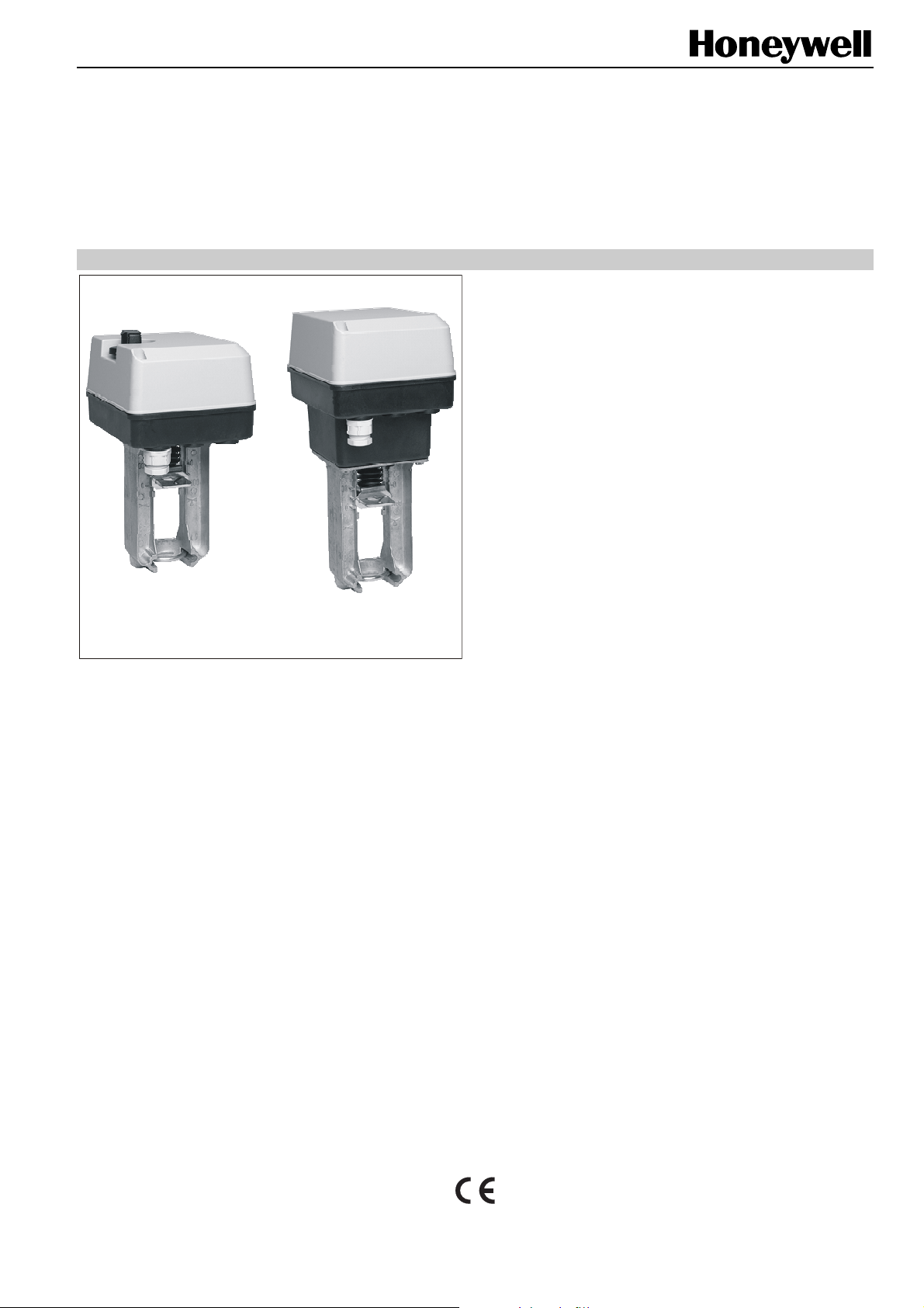
ML6420A/ML6425A,B
Electric Linear Valve Actuators
SPECIFICATION DATA
FEATURES
• Quick and easy installation
• No separate linkage required
• No adjustments
• Low power consumption
• Force-limiting end switches
• Spring-return models
• Manual operator
• Models for low and line voltage
ML6420 ML6425
APPLICATION
The ML6420A / ML6425A,B actuators enable floating control,
and are suitable for use in conjunction with ON/OFF or
floating single-pole, double-throw (SPDT) control outputs.
They can operate Honeywell’s standard valves in heating,
ventilation, and air conditioning (HVAC) applications.
• Synchronous motor
• Corrosion-resistant design
• Maintenance-free
SPECIFICATIONS
Temperature Limits
Ambient operating limits -10...+50 °C at 5...95% RH
Ambient storage limits -40...+70 °C at 5...95% RH
Medium valve
temperature Max. 150 °C (220 °C with
High-Temperature kit)
Protection
Protection standard
per DIN 40050 IP54
Insulation per
DIN EN60730 Class II
Flame retardant as per UL 94-V0
(with metal cable gland)
Wiring
Wiring terminals 1.5 mm
Cable entry PG13.5 and two additional
knock-outs PG11 and
PG13.5
Weight
non-spring return type 1.3 kg
spring return type 2.4 kg
Material
Cover ABS-FR
Base glass fiber reinforced plastic
Yoke aluminum diecast
Dimensions See Fig. 1 on page 3
2
® U.S. Registered Trademark EN0B-0351GE51 R0606
Copyright © 2006 Honeywell Inc. • All rights reserved
Page 2
ML6420A/ML6425A,B
model
supply voltage
power consumption 4 VA 6 VA 11 VA 12 VA 6.5 VA
signal input 1
signal input 2
stroke 20 mm
run time at 50 Hz 1 min 0.5 min 1.8 min 1 min 0.5 min
close-off force
spring return time -spring return direction (upon power
failure)
ML6420
A3007
Supply voltage between terminals 1 and 24 V∼;
actuator stem extended. Two-way valve:“closed“,
Supply voltage between terminals 2 and 24 V∼;
actuator stem retracted. Two-way valve:“open“,
ML6420
A3023
24 Vac ±15%, 50/60 Hz
three-way valve port A-AB:“open“
three-way valve port A-AB:“closed“.
--
ML6425
A3006
actuator
stem
extends
ML6425
actuator
B3005
stem
retracts
ML6425
A3014
Supply voltage between terminals N and Ph 1;
actuator stem extended. Two-way valve:“closed“,
Supply voltage between terminals N and Ph 2;
actuator stem retracted. Two-way valve:“open“,
three-way valve port A-AB:“closed“.
≥600 N
≈12 s
actuator
stem
extends
ML6425
B3021
230 Vac +10/-15%, 50/60 Hz
three-way valve port A-AB:“open“
actuator
stem
retracts
ML6420
A3015
--
--
ML6420
A3031
OPERATION
General
The drive of a synchronous motor is converted into linear
motion of the actuator stem by using a spur gear transmission. The actuator stem is connected with the valve stem
by a button keyed retainer connection.
An integrated spring package limits the stem force to a
factory-adjusted value in either direction.
Installed microswitches switch off the actuator precisely when
the specified stem force is reached.
Manual Operation
Actuators without spring return are equipped with a manual
operator used in case of power failure. Manual operation is
possible only after the power supply has been switched off or
disconnected.
To operate, push the manual operator knob down and turn
clockwise to move the stem downward and counter-clockwise
to move the stem upward. If the actuator returns to automatic
control, the manual operator knob unlocks automatically.
In the case of actuators with spring return, the manual
operator is located under the cover.
Spring Return
The ML6425A,B spring return actuators provide a defined
safety position of the valve in case of power failure.
The spring return actuators are shipped from the factory with
a shipment stop (to lock the knob) in order to allow connection
of the stem button retainer to the valve stem without power
supply.
Electrical Installation
The actuators are delivered with a pre-installed cable gland
PG13.5 (21.2 mm) and two additional knock-outs for PG11
(18.9 mm) and PG13.5.
Accessories
Auxiliary Switches
The actuators can be equipped on site with an auxiliary switch
unit with two switches. Their switching points are adjustable
over the full length of the actuator stroke. The switches can
be used to switch pumps or provide remote indication of any
stroke position.
Part number: 43191680 – 005.
Auxiliary Potentiometers
Auxiliary potentiometers are available for mounting on site.
They can be used as feedback potentiometer and/or to
provide remote indication of the valve position.
Part number: 43191679 - 011 (10 kΩ)
Part number: 43191679 - 012 (220 Ω)
High Temperature Kit
(for applications >150 °C medium temperature)
order number
High-Temperature Kit
43196000-001
43196000-002
43196000-038
valve DN
V5011A/V5011K
V5013A/V5013G
V5011R/V5013R
V5328A/V5329A
V5011A
V5013A/V5013G
V5328A/V5329A
V5049A
V5050A
V5328A
V5016A
V5025A
V5049A (PN25/40)
V5050 (PN16)
V5050 (PN25/40)
15 – 40
15 – 40
15 – 50
15 – 32
50
50
40 – 80
15 – 65
15 – 80
100 – 150
100 – 150
100 – 150
80 – 100
100 – 150
100
EN0B-0351GE51 R0606 2
Page 3

ML6420A/ML6425A,B
2
2
CLOSE-OFF PRESSURE RATINGS in kPa
Stem Force 600 N
Stroke 20 mm
Valve mm 15 20 25 32 40 50 65 80
Size inch ½ ¾ 1 1 ¼ 1 ½ 2 2 ½ 3
Valves Close-Off Pressure Ratings
V5011R 1600 1600 1000 700 460 260
V5328A 1600/1000 1000 1000 600 350 200 120 50
V5095A 1600 1600 1600 1600 1600 1600 1600
V5016A 1600 1600 1600 1600 1600 1600 1600 1600
V5025A 2500 2500 2500 2500 2500 2500 2500 2500
V5049A 1600/1000 1000 1000 600 350 200 120
V5013R 1600 1600 1000 700 460 260
V5329C (PN6) 600 600 600 600 480 260 160 100
V5329A (PN16) 1000 1000 1000 790 480 260 160 100
V5050A 1000 1000 1000 600 350 200 120 50
For details on the valves, see following Specification Data No.:
V5011R EN0B-0064GE51 5049A EN0B-0238GE51
V5011S EN0B-0085GE51 V5329A/5050A EN0B-0310GE51
V5016A EN0B-0440GE51 V5025A EN0B-0442GE51
V5095A EN0B-0412GE51 V5013R EN0B-0065GE51
V5328A EN0B-0432GE02
DIMENSIONS
135x(161)
67.4
135x(161)
67.4
284
4
100
0 100
1000
233
0
322 (with High-Temperature Kit: 402 mm)
141
1000
192
364 (with High-Temperature Kit: 444 mm)
Fig. 1. Dimensions in mm
EN0B-0351GE51 R0606
3
Page 4

ML6420A/ML6425A,B
WIRING
M
24~
1
2
24 V~
24 V
4
5
ML6420A
without spring return
Fig. 2. Wiring 24 V~ models
N
N
230 V~
M
1
2
L
4
5
ML6420A
without spring return
Fig. 3. Wiring 230 V~ models
AUXILIARY SWITCHES (OPTION)
Part number: 43191680 – 005.
M
ML6425A,B
with spring return
M
ML6425A,B
with spring return
24 V ~
B
1
2
4
5
N
B
1
2
4
5
safety
temp.
limiter
safety
temp.
limiter
24 V ~
24 V
N
230 V~
L
auxiliary switches:
250 Vac / 5 (3) A
Fig. 4. Wiring auxiliary switch
Manufactured for and on behalf of the Environmental and Combustion Controls Division of Honeywell Technologies Sàrl, Ecublens, Route du Bois 37, Switzerland by its Authorized Representative:
Automation and Control Solutions
Honeywell GmbH
Böblinger Straβe 17
D-71101 Schönaich
Phone: (49) 7031 63701
Fax: (49) 7031 637493
http://europe.hbc.honeywell.com
Subject to change without notice. Printed in Germany
EN0B-0351GE51 R0606
1 2
S1 S2
3
5
4
6
 Loading...