

Page 1
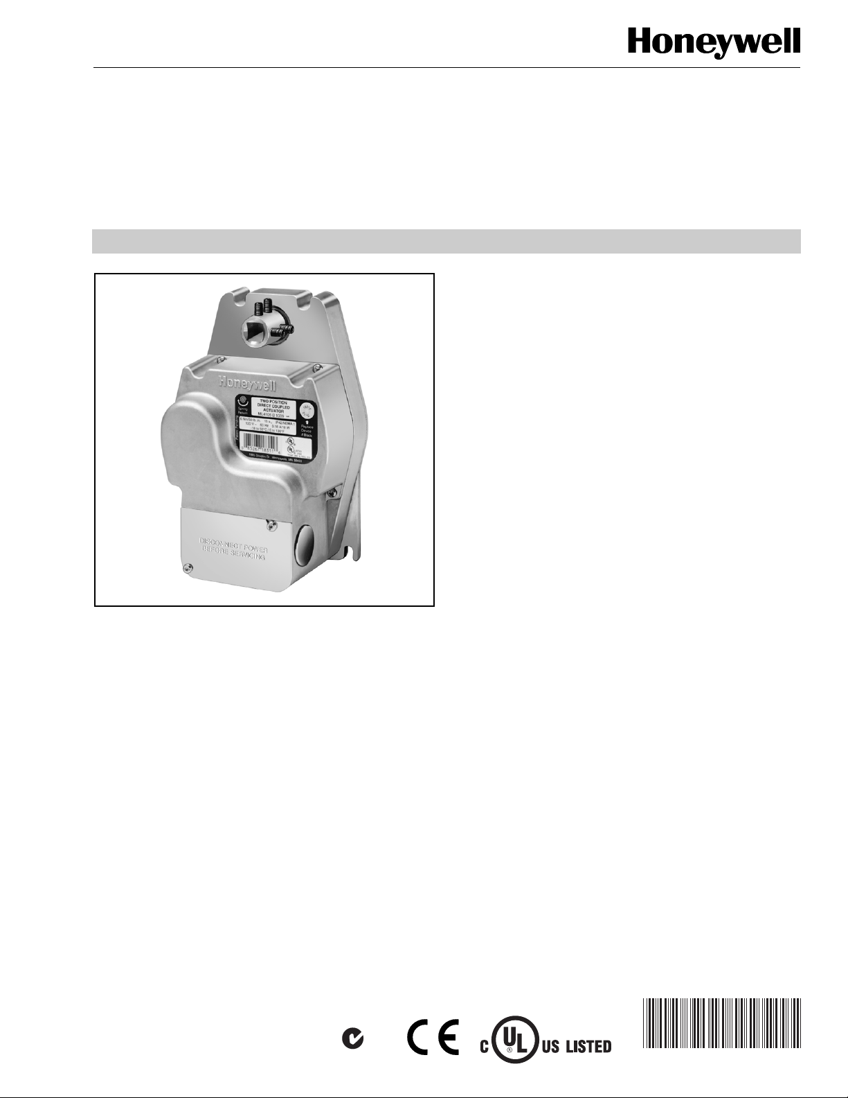
ML4105, ML4115, ML8105, ML8115
Fast-Acting, Two-Position Actuators
FOR FIRE/SMOKE CONTROL APPLICATIONS
PRODUCT DATA
FEATURES
• 30 lb-in. (3.4 N•m) or 50 lb-in. (5.7 N•m) minimum
driving torque at 350°F (176°C).
• Integral spring return ensures level of return torque.
• Fifteen-second spring return timing.
• No special cycling required during long-term holding.
(See Operation section.)
• No audible noise during holding.
• Patent pending design eliminates need for limit
switches to reduce power consumption.
• Models available for 24, 120, and 230 Vac.
• Ninety-five degree angle of rotation.
• Actuator holds rated torque at reduced power level.
• Die-cast aluminum housing.
• Housing design allows flush mounting to damper.
• Integral junction box with three conduit openings
eliminates need for separate wiring box.
• High-temperature indicator included.
APPLICATION
The ML4105, ML4115, ML8105, and ML8115 Fast-Acting,
Two-Position Actuators are spring return direct coupled
actuators (DCA) with an integral junction box for on/off
damper control. The actuator accepts an on/off signal from a
single-pole, single-throw (spst) controller. Models are
available with clockwise (cw) or counterclockwise (ccw) spring
return and are designed to operate reliably in smoke control
systems requiring Underwriter’s Laboratories Inc. UL555S
ratings up to 350°F.
® U.S. Registered Trademark
Copyright © 2003 Honeywell International Inc.
All Rights Reserved
N314
APPLICABLE LITERATURE
— Motor/Actuator Selection Guide
for Damper Applications 63-8419
— Engineering Manual of Automatic Control
(also called The Gray Manual) 77-1100
— Direct Coupled Actuator
Quick Selection Guide 63-8553
— Damper Torque Calculator 63-8437
Contents
Application ........................................................................ 1
Features ........................................................................... 1
Applicable Literature ......................................................... 1
Specifications ................................................................... 2
Ordering Information ........................................................ 2
Installation ........................................................................ 4
Operation .......................................................................... 6
Checkout .......................................................................... 6
63-2540-9
Page 2

ML4105, ML4115, ML8105, ML8115 FAST-ACTING, TWO-POSITION ACTUATORS
SPECIFICATIONS
Models: See Table 1.
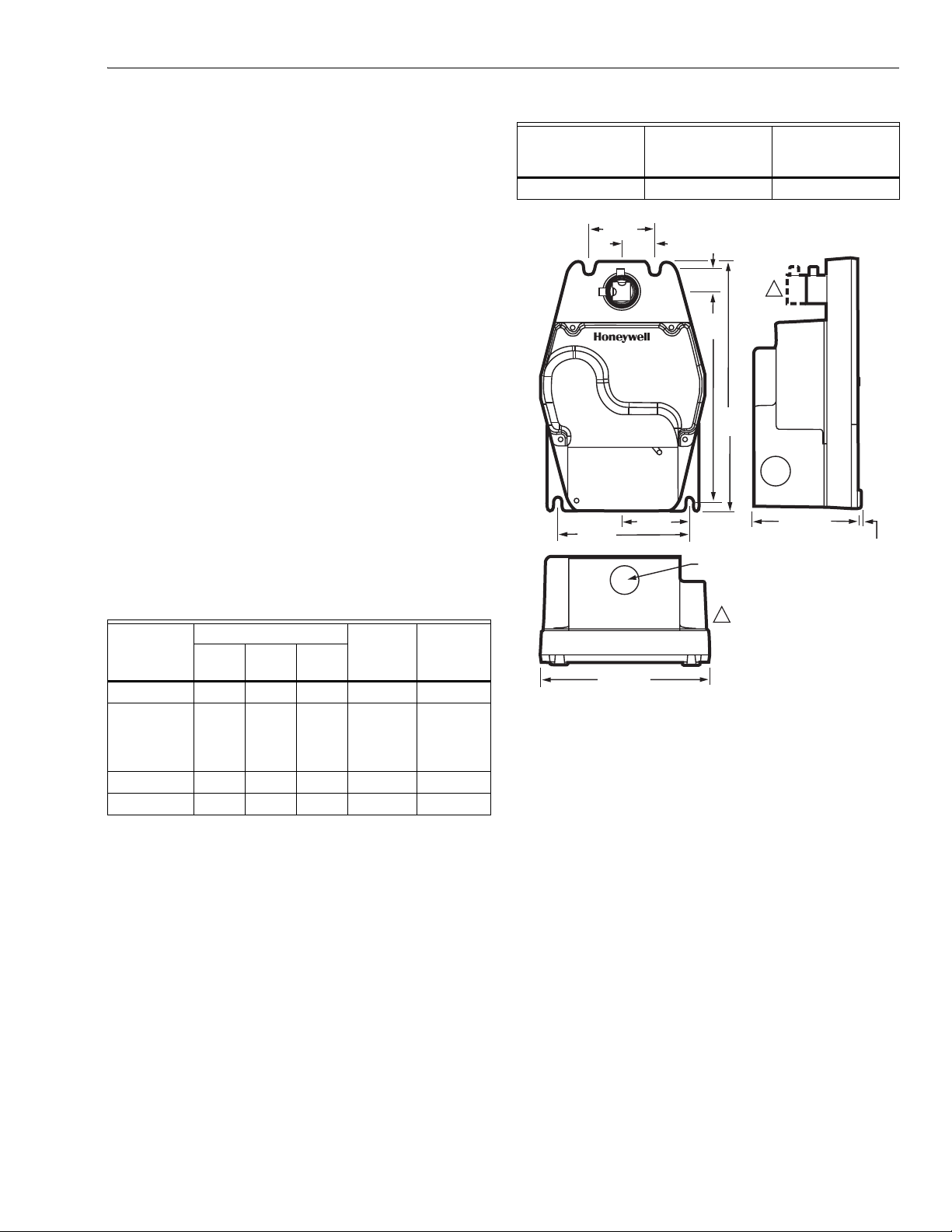
Dimensions: See Fig. 1.
Minimum Damper Shaft Length: 1-3/4 in. (45 mm).
Device Weight: 5 lb (2.3 kg).
Stroke: 95° ± 3°, mechanically limited.
Electrical Ratings: See Table 1.
Electrical Connections:
ML4105A,B, ML4115A,B, ML8105, ML8115: Two color coded
16 in. leads; includes ground screw.
ML4105C1008, ML4105D1007: Terminal block and ground
screw with option for connecting thermal switch.
ML4105C1016, ML4105D1015, ML4115C,D: 1m appliance
cable.
Three 7/8 in. holes for conduit connections (fittings not
included).
Mounting: 3/8 to 1/2 in. square or round damper shafts.
Actuator can be mounted with shaft in any position. Secure
hub to shaft with:
ML4105A,B, ML8105: Four 1/4-28 UNF set screws. Use
1/8 in. Allen wrench to tighten set screws.
ML4105C,D: Four 3 mm set screws. Use 3 mm Allen
wrench to tighten set screws.
ML4115, ML8115: Two 1/4-28 UNF set screws. Use 1/8 in.
Allen wrench to tighten set screws.
IMPORTANT
Honeywell does not recommend using linkages with
these actuators because side-loading of the output
hub reduces actuator life.
Temperature Ratings:
Ambient: 0°F to 130°F (-18°C to 55°C).
Shipping and Storage: -40°F to 140°F (-40°C to 60°C).
IMPORTANT
The actuator is designed to meet UL555S standards
at 350°F (176°C). The actuator must be tested with
the damper to achieve this rating.
Humidity Ratings: 5% to 95% RH noncondensing.
Noise Rating (Maximum):
Driving Open: 65 dBA at 1m.
Holding: 20 dBA at 1m (no audible noise).
Controller Type:
ML4105A,B, ML4115A,B: Line voltage (120 Vac),
two-position, spst (Series 40).
ML4105C,D, ML4115C,D: Line voltage (230 Vac),
two-position, spst (Series 40).
ML8105, ML8115: Low voltage (24 Vac),
two-position, spst (Series 80).
Table 1. ML4105, ML4115, ML8105, ML8115 DCA Models.
Spring
Return
Model
ML4105A ccw 0.20A, 18W 0.11A, 9W 50 (5.7) 120 +10%,
ML4105B cw
ML4105C ccw 0.12A, 22W 0.08A, 10W 50 (5.7) 230 ±10%,
ML4105D cw
ML4115A ccw 0.18A, 18W 0.11A, 9W 30 (3.4) 120 ±10%,
ML4115B cw
ML4115C ccw 0.13A, 18W 0.10A, 11W 30 (3.4) 230 ±10%,
ML4115D cw
ML8105A ccw 20 VA 8 VA 50 (5.7) 24
ML8105B cw
ML8115A ccw 16 VA 8 VA 30 (3.4)
ML8115B cw
Torque Rating (at rated voltage):
Typical Holding: 100 lb-in. (11.3 N•m).
Spring Return:
Stall Maximum:
350°F Driving:
Direction
ML4105, ML8105: 40 lb-in. (4.5 N•m).
ML4115, ML8115: 30 lb-in. (3.4 N•m).
ML4105, ML8105: 240 lb-in. (27 N•m).
ML4115, ML8115: 150 lb-in. (17 N•m).
ML4105, ML8105: 50 lb-in. (5.7 N•m).
ML4115, ML8115: 30 lb-in. (3.4 N•m).
Power Consumption Torque
in lb-in.
(N•m)
Voltage
Input
in VacRunning Holding
-15%, 60 Hz
50/60 Hz
60 Hz
50/60 Hz
+20%, -10%,
50/60 Hz
ORDERING INFORMATION
When purchasing replacement and modernization products from your TRADELINE® wholesaler or distributor, refer to the
TRADELINE® Catalog or price sheets for complete ordering number.
If you have additional questions, need further information, or would like to comment on our products or services, please write or
phone:
1. Your local Honeywell Automation and Control Products Sales Office (check white pages of your phone directory).
2. Honeywell Customer Care
1885 Douglas Drive North
Minneapolis, Minnesota 55422-4386
In Canada—Honeywell Limited/Honeywell Limitée, 35 Dynamic Drive, Scarborough, Ontario M1V 4Z9.
International Sales and Service Offices in all principal cities of the world. Manufacturing in Australia, Canada, Finland, France,
Germany, Japan, Mexico, Netherlands, Spain, Taiwan, United Kingdom, U.S.A.
63-2540—9 2
Page 3
ML4105, ML4115, ML8105, ML8115 FAST-ACTING, TWO-POSITION ACTUATORS
Timing (At Rated Torque and Voltage):
Drive Open:
ML4105, ML8105: 15 sec maximum, 14 sec typical.
ML4115: 25 sec maximum, 18 sec typical.
ML8115: 25 sec maximum, 22 sec typical.
Spring Close: 15 seconds.
Cycling Requirements:
Prolonged holding-period (1 year) testing of these actuators
has been performed with no spring return failures. The
actuator and the internal spring are designed to require no
special cycling during long-term holding.
Honeywell recommends following all local, state and national
codes for periodic testing of the entire smoke control
system. Refer to National Fire Protection Association (NFPA)
National Fire Codes®: NFPA90A, NFPA92A and NFPA92B
for your application.
NFPA recommends periodic examination of each fire/smoke
damper (semi-annually or annually) to ensure proper
performance.
Design Life (at Rated Voltage): 60,000 full stroke cycles.
Approvals: See Table 2.
Environmental Protection Ratings: See Table 3.
Accessories:
201391 Shaft Adapter for 3/8 in. shafts (not supplied with
actuator).
205649 Mounting Bracket (not supplied with actuator).
Table 3. Environmental Ratings.
ML4105C1016
ML4105D1015
All Devices
ML4105C1008
ML4105D1007
NEMA1 IP40 IP54
2 (51)
1 (25)
5/8
4 (102)
(17)
6 3/8
(161)
7 1/2
(192)
2 (51) 3 5/16 (84)
7/8 (22)
1
ML4115C,D
1/16 (2)
Table 2. Approvals.
ML4105
C1008,
D1007
C1016,
D1015
ML4115A,B
UL/cUL X X X X
UL873 Plenum
XXXX X
Rating, File No.
E4436; Guide
No. XAPX.
CE X X X
C-TICK X X X
ML4115C,D
ML8105,
ML8115A,B
ML4115/ML8115 HAVE SMALLER
1
HUB WITH TWO SET SCREWS.
ML4105/ML8105 HAVE LONGER
HUB WITH FOUR SET SCREWS.
5 1/8 (129)
Fig. 1. ML4105/ML4115/ML8105/ML8115
dimensional drawing in in. (mm).
M13053A
3 63-2540—9
Page 4

ML4105, ML4115, ML8105, ML8115 FAST-ACTING, TWO-POSITION ACTUATORS
INSTALLATION
When Installing this Product...
1. Read these instructions carefully. Failure to follow
them could damage the product or cause a hazardous
condition.
2. Check the ratings given in the instructions and on the
product to make sure the product is suitable for your
application.
3. Installer must be a trained, experienced service
technician.
4. After installation is complete, check out product
operation as provided in these instructions.
IMPORTANT
All wiring must agree with applicable codes,
ordinances and regulations.
WARNING
Electrical Power Hazard.
Line voltage can cause death or serious injury
and short equipment circuitry.
Disconnect power supply before installation.
1
2
CAUTION
Electrical Shock or Equipment Damage Hazard.
Low voltage can shock individuals or short
equipment circuitry.
Disconnect power supply before installation.
Location and Mounting
The ML4105, ML4115, ML8105 and ML8115 DCA are
designed to open a damper by driving the damper shaft in
either clockwise or counterclockwise direction.
The actuator housing has two slots on the bottom that, with a
205649 Mounting Bracket, secure it flush to a damper box
(see Fig. 2). When mounted correctly, these slots allow the
actuator to float without rotating relative to the damper shaft.
CAUTION
Equipment Damage Hazard.
Tightly securing actuator to damper housing can
damage actuator.
Mount actuator to allow it to float along its vertical axis.
NOTE: ML4105, ML4115, ML8105, and ML8115 Actuators
are shipped in the fully closed position.
ENSURE THAT MOUNTING ASSEMBLY PREVENTS ACTUATOR
1
ROTATION AND ALLOWS ACTUATOR TO FLOAT ALONG
INDICATED AXIS. WHEN TOO TIGHT, THE RESULTING BINDING
CAN DAMAGE THE ACTUATOR OR REDUCE TORQUE OUTPUT.
2
ACCESSORY MOUNTING BRACKET IS NOT SUPPLIED WITH
THE ACTUATOR.
Fig. 2. Mounting actuator to damper housing.
M13054A
Preparation
Before mounting the actuator onto the damper shaft,
determine the damper shaft size (3/8 in. to 1/2 in.
[10 mm to 13 mm]).
If damper shaft is 3/8 in. (10 mm) round or square, use part
number 201391 Shaft Adapter (not supplied with actuator).
Place adapter opposite set screws (see Fig. 3).
NOTE: The damper shaft adapter centers a 3/8 in. (10 mm)
damper shaft in the hub. Failure to use adapter can
cause mounting screws to loosen. A 1/2 in. (13 mm)
damper shaft does not require an adapter.
SHAFT ADAPTER
63-2540—9 4
M2064
Fig. 3. Using damper shaft adapter for
3/8 in. (10 mm) damper shafts.
Page 5

ML4105, ML4115, ML8105, ML8115 FAST-ACTING, TWO-POSITION ACTUATORS
Installation
CAUTION
Device Malfunction Hazard.
Improper set screw tightening causes device
malfunction.
Tighten set screws with proper torque to prevent
damper shaft slippage.
CAUTION
Actuator Damage Hazard.
Using actuator as shaft bearing causes device
damage.
Use actuator only to supply rotational torque. Avoid
any side loads to actuator output coupling bearings.
To install actuator, proceed as follows:
1. Place actuator over damper shaft; and hold mounting
bracket in place. See Fig. 2.
2. Mark screw holes on damper housing.
3. Remove actuator and mounting bracket.
4. Drill or center-punch holes for mounting screws (or use
no.10 self-tapping sheet metal screws).
5. Turn damper blades to desired normal (closed) position.
6. Place actuator and mounting bracket back into position
and secure bracket to damper box with sheet metal
screws.
7. Tighten set screws securely into damper shaft using
minimum 30 lb-in., maximum 60 lb-in. torque. Use
1/8 in. or 3 mm Allen wrench (see Specifications for
details) to tighten set screws.
Wiring
See Fig. 4 through 8 for typical wiring diagrams.
( )
L1
( )
L2
M17585A
L1
L2
M17589A
L1
L2
M17588A
24 VAC
( )
120 V
( )
( )
230 VAC
( )
Fig. 4. Typical 24 Vac wiring.
AC
Fig. 5. Typical 120 Vac wiring.
Fig. 6. Typical 230 Vac wiring.
RED
BLACK
BLACK
WHITE
BROWN
BLUE
WARNING
Electrical Power Hazard.
Line voltage can cause death or serious injury and
short equipment circuitry.
Disconnect power supply before installation.
CAUTION
Electrical Shock or Equipment Damage Hazard.
Low voltage can shock individuals or short
equipment circuitry.
Disconnect power supply before installation.
IMPORTANT
1. All wiring must comply with local electrical codes,
ordinances and regulations.
2. Voltage and frequency of transformer used with
ML8105 and ML8115 must correspond with the
characteristics of power supply and actuator.
3. Use wires rated for at least 75°C (167°F).
( )
L2
( )
L1
M17586A
230 VAC
3
2
1
L1
Fig. 7. 230 Vac terminal-strip wiring.
200 F
( )
L1
230 VAC
( )
L2
M17587A
93 C
L1
2
3
1
Fig. 8. 230 Vac terminal-strip wiring with a thermal fuse.
NOTE: Terminal strip included with ML4105C1008 and
ML4105D1007.
5 63-2540—9
Page 6

ML4105, ML4115, ML8105, ML8115 FAST-ACTING, TWO-POSITION ACTUATORS
OPERATION
The ML4105, ML4115, ML8105, and ML8115 DCA are
designed for use in Smoke Control Systems. If power fails, the
actuator spring returns to the 0° position. The actuator mounts
flush with the damper box. The actuator drives from 0° to 95°
and spring returns back to 0°.
IMPORTANT
The actuators are operated by an spst two-position controller.
When using an spst two-position controller, the actuator drives
to the damper fully open position when controller contact
makes and spring returns to the damper fully closed position
when controller contact breaks. The actuator drops to holding
power level on detection of stall, independent of hub position.
Cycling
The actuator and the internal spring are designed so that no
special cycling during long-term holding is required.
Honeywell recommends following all local, state, and national
codes for periodic testing of the entire smoke control system.
Refer to National Fire Protection Association (NFPA) National
Fire Codes
application.
Temperature Indicator
The temperature indicator, located on the cover of the
actuator, provides evidence that the ambient temperature has
exceeded 200°F (93°C). This is an indication that something
in the building has caused temperatures to rise well above the
long-term actuator operation temperature. While the actuator
is capable of operating at 350°F (176°C) for extended periods
of time, this indicator provides a visual signal that the actuator
has been exposed to high temperatures for an undetermined
period of time. The indicator provides a visual indication to fire
authorities regarding the extent of damage after an event in
the building.
IMPORTANT
NOTE: The actuator is designed to operate for 30 minutes
A break in power of less than two seconds can cause
the actuator to spring-return 5 degrees or less and
remain in place until a break in power of longer
duration.
®
: NFPA90A, NFPA92A, and NFPA92B for your
If the indicator turns black, replace the actuator.
during a one-time excursion to 350°F (176°C).
CHECKOUT
ML4105A,B and ML4115A,B (120 Vac model)
1. Verify that the indicator has not turned black (see
Temperature Indicator section).
2. Check damper position.
3. Connect 120 Vac to the black and white leadwires to
drive the damper to the open position. The actuator
should drive the damper.
4. If the actuator does not run, remove power for at least
two seconds.
5. If the actuator spring returns, allow it to close entirely,
then return to step 3.
6. If the actuator does not spring return, verify that the
actuator is properly installed. See Installation section.
7. If the actuator is correctly installed but neither runs nor
spring returns, replace the actuator.
ML4105C,D and ML4115C,D (230 Vac model)
1. Verify that the indicator has not turned black (see
Temperature Indicator section).
2. Check damper position.
3. Connect 230 Vac to the blue and brown leadwires to
drive the damper to the open position. The actuator
should drive the damper.
4. If the actuator does not run, remove power for at least
two seconds.
5. If the actuator spring returns, allow it to close entirely,
then return to step 3.
6. If the actuator does not spring return, verify that the
actuator is properly installed. See Installation section.
7. If the actuator is correctly installed but neither runs nor
spring returns, replace the actuator.
ML8105 and ML8115 (24 Vac model)
1. Verify that the indicator has not turned black (see
Temperature Indicator section).
2. Check damper position.
3. Connect 24 Vac to the red and black leadwires to drive
the damper to the open position. The actuator should
drive the damper.
4. If the actuator does not run, remove power for at least
two seconds.
5. If the actuator spring returns, allow it to close entirely,
then return to step 3.
6. If the actuator does not spring return, verify that the
actuator is properly installed. See Installation section.
7. If the actuator is correctly installed but neither runs nor
spring returns, replace the actuator.
63-2540—9 6
Page 7

D Montageanweisung
F Instructions d’Installation
I Istruzioni per I’Installazione
NL Installatievoorschrift
DK Installasjonsinstruks
N Installationsinstrukioner
SF Asennusohje
S Installations Instrukioner
E Instrucciones de montage
ML4105, ML4115, ML8105, ML8115 FAST-ACTING, TWO-POSITION ACTUATORS
AA1, A4
24 VAC
!
120 VAC
ASSEMBLY
EINBAU
D
MONTAGE
F
MONTAGGIO
I
MONTAGE
NL
MONTERE
DK
MONTERING
N
ASENTAMINEN
FIN
MONTERA
S
MONTAJE
E
M11874
a
b
M11875
A2
a
c
M11876
A3
A5
A6
MIN: 45 lb-in. (5.1 Nm)
MAX: 60lb-in. (6.8 Nm)
b
b
c
d
HEX
4mm
a
b
M12030
b
M11881
7 63-2540—9
a
M11882
a
Page 8

ML4105, ML4115, ML8105, ML8115 FAST-ACTING, TWO-POSITION ACTUATORS
BB1B2
24 VAC
!
120 VAC
a
DISASSEMBLY
AUSBAU
D
DÉMONTAGE
F
SMONTAGGIO
I
DEMONTAGE
NL
AFMONTERE
DK
DEMONTERE
N
PURKAMINEN
FIN
NEDMONTERA
S
DESMONTAJE
E
M11884
M11887
M11888
a
b
b
HEX
4mm
M11886
B4B3
M11885
National Fire Codes® is a registered trademark of the National Fire Protection Association (NFPA).
Automation and Control Solutions Honeywell International Honeywell Europe S.A. Honeywell Latin American
Honeywell International Inc. Honeywell Limited-Honeywell Limitée Control Products 3 Avenue du Bourget
1985 Douglas Drive North 35 Dynamic Drive Honeywell Building 1140 Brussels 480 Sawgrass Corporate Parkway
Golden Valley, MN 55422 Scarborough, Ontario 17 Changi Business Park Central 1 Belgium Suite 200
M1V 4Z9 Singapore 486073 Sunrise FL 33325
63-2540—9 B.B. Rev. 5-03 www.honeywell.com
Region
 Loading...